1
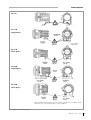
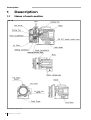
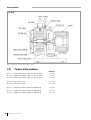
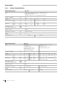
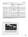
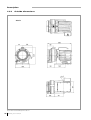
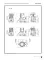
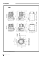
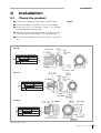
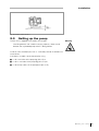
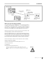
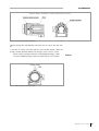
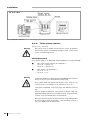
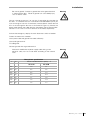
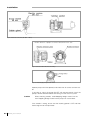
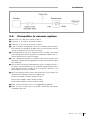
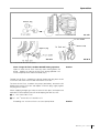
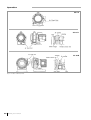
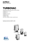
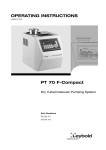
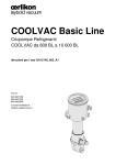
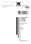
Leybold SC 5D, SC 15D, SC 30D, Dry Scroll Vacuum Pump (505)872-0037 idealvac.com To Our Website idealvac.com Contents Section Page General safety information . . . . . . . . . . . . . . . . . . . . . . . . . . . . . . . . . . . . . . 3 1 Description . . . . . . . . . . . . . . . . . . . . . . . . . . . . . . . . . . . . . . . . . . . . . . . . . . . 6 1.1 Name of each section . . . . . . . . . . . . . . . . . . . . . . . . . . . . . . . . . . . . . . . . . . . . 6 1.2 Order Information . . . . . . . . . . . . . . . . . . . . . . . . . . . . . . . . . . . . . . . . . . . . . . . 8 1.3 Technical Data. . . . . . . . . . . . . . . . . . . . . . . . . . . . . . . . . . . . . . . . . . . . . . . . . . 9 1.3.1 Motor Related Data. . . . . . . . . . . . . . . . . . . . . . . . . . . . . . . . . . . . . . . . . . . . . 10 1.3.2 Performance data . . . . . . . . . . . . . . . . . . . . . . . . . . . . . . . . . . . . . . . . . . . . . . 11 1.3.3 Outside dimensions. . . . . . . . . . . . . . . . . . . . . . . . . . . . . . . . . . . . . . . . . . . . . 12 2 Installation . . . . . . . . . . . . . . . . . . . . . . . . . . . . . . . . . . . . . . . . . . . . . . . . . . 15 2.1 Check the product . . . . . . . . . . . . . . . . . . . . . . . . . . . . . . . . . . . . . . . . . . . . . 15 2.2 Operating environment . . . . . . . . . . . . . . . . . . . . . . . . . . . . . . . . . . . . . . . . . . 16 2.3 Setting up the pump . . . . . . . . . . . . . . . . . . . . . . . . . . . . . . . . . . . . . . . . . . . . 17 2.4 Electrical Connections. . . . . . . . . . . . . . . . . . . . . . . . . . . . . . . . . . . . . . . . . . . 18 2.4.1 Single-phase motors . . . . . . . . . . . . . . . . . . . . . . . . . . . . . . . . . . . . . . . . . . . . 18 2.4.2 Three-phase motors . . . . . . . . . . . . . . . . . . . . . . . . . . . . . . . . . . . . . . . . . . . . 22 2.5 Connection to vacuum system . . . . . . . . . . . . . . . . . . . . . . . . . . . . . . . . . . . . 25 3 Operation . . . . . . . . . . . . . . . . . . . . . . . . . . . . . . . . . . . . . . . . . . . . . . . . . . . 26 3.1 Start up. . . . . . . . . . . . . . . . . . . . . . . . . . . . . . . . . . . . . . . . . . . . . . . . . . . . . . 27 3.2 Pumping . . . . . . . . . . . . . . . . . . . . . . . . . . . . . . . . . . . . . . . . . . . . . . . . . . . . . 28 3.3 Pumping vapor (air flush operation) . . . . . . . . . . . . . . . . . . . . . . . . . . . . . . . . . 28 3.4 Shut down . . . . . . . . . . . . . . . . . . . . . . . . . . . . . . . . . . . . . . . . . . . . . . . . . . . 31 4 Maintenance . . . . . . . . . . . . . . . . . . . . . . . . . . . . . . . . . . . . . . . . . . . . . . . . . 32 4.1 Table - Maintenance . . . . . . . . . . . . . . . . . . . . . . . . . . . . . . . . . . . . . . . . . . . . 34 4.2 Leybold Service. . . . . . . . . . . . . . . . . . . . . . . . . . . . . . . . . . . . . . . . . . . . . . . . 35 4.3 Disposal . . . . . . . . . . . . . . . . . . . . . . . . . . . . . . . . . . . . . . . . . . . . . . . . . . . . . 35 5 Troubleshooting . . . . . . . . . . . . . . . . . . . . . . . . . . . . . . . . . . . . . . . . . . . . . . 36 6 Spare parts . . . . . . . . . . . . . . . . . . . . . . . . . . . . . . . . . . . . . . . . . . . . . . . . . . 37 EC Conformance Declaration. . . . . . . . . . . . . . . . . . . . . . . . . . . . . . . . . . . 38 Figures The first digit of a reference, (1/2) for example, is the figure number; the second digit is its item number in this figure. We reserve the right to modify the design and the specified data. The illu strations are not binding. 2 GA01423_0102 - 11/2004 Safety information General safety information Indicates procedures that must be strictly observed to prevent hazards to persons. Warning Indicates procedures that must be strictly observed to prevent damage to, or destruction of the appliance. Caution The Leybold Oil-free Scoll vacuum pump is designed for safe and efficient operation when used properly and in accordance with this manual. It is the responsibility of the user to carefully read and strictly observe all safety pre cautions described in this section and throughout the manual. This product must be operated and maintained by trained personnel only. Consult local, state, and national agencies regarding specific requirements and regulati ons. Address any further safety, operation and/or maintenance questions to your nearest Leybold Vacuum office. Failure to observe the following precautions could result in serious personal injury. ■ Never pump toxic, explosive, flarmmable, corrosive gases, chemicals, solvents or powders. Flowing substances, explosion or fire can cause bodily injury. Warning ■ Install in an area without explosive or flammable substances. Oherwise, it can cause explosion or fire. ■ Wiring must be done by a qualified electrician. Otherwise, electric shock may occur. ■ Prevent short-circuit with ground fault circuit interuptor (GFCI) of proper capacity. Failure to do so can result in electric shock or fire. ■ Ask specialist to perform repairs. If not , it can cause failure, damage or shorter lifetime. Trained customers may perform maintenance themselves. ■ Be sure to install a main disconnect switch. Failure to do so can result in damage, fire, or injury. ■ Be sure to disconnect the electric source before wiring or inspection. Failure to do so can result in electric shock or damage by the rotating fan. Cut off electric Source ■ Be sure to ground. Failure to ground can result in electric shock or fire. Be sure to ground GA01423_0102 - 11/2004 3 Safety information Do not touch Never put fingers or foreign matter into the pump's inlet or the clearance of cooling fins. If done, it can cause injury. Avoid moisture Install in an area which is not exposed to moisture such as rain or steam. Exposure to moisture can cause eIectric shock. Do not alter Never alter the equipment. Modifications can damage the equipment of shorten its lifetime. With a thermal protector Be sure to check Wiring diagram before connecting a power supply. Failure to do so can result in damage. Pumps with single-phase motors have an internal thermal pro tector. This motor restarts without warning after the protector trips. Be sure to switch off the electric power before maintenance or inspection. Failure to do so can result in electric shock or bodily injury by rotating objects. Install in a proper location Install in a proper location. ■ Install on a level foundation (an inclination of less than 5°) ■ in a location free of dirt or dust from iron, stone or wood. ■ in a location free of corrosive gas. Failure to install in a proper location can result in damage, decrease in performance or shorter lifetime. Use designated temperature Use at ambient temperatures of 5 - 40 °C (during operation). Operating outside of this range can cause damage or shorten lifetime. Do not operate when the fan cover is removed. Do not operate, when the terminaI cover is removed. Do not operate the single-phase pump when its condenser cover is removed. Conduct periodic maintenance 4 Conduct periodic maintenance and inspections. Failure to do so can cause damage or shorter lifetime. Maintenance after pump is cool Do the maintenance after the pump has fully cooled down. Performing maintenance on a hot pump can cause burns. Start or stop after closing isolation valve Be sure to close the isolation valve between pump and vacu um system (chamber) during startup and shutdown. GA01423_0102 - 11/2004 If this valve is open, debris attached to inside of pump can be drawn back into the vacuum chamber. Description SC 5 D Terminal Cover Electric Shock Condenser Cover SC 15 D Single phase SC 15 D Three phase SC 30 D Single phase SC 30 D Three phase Always keep warning stickers clean. If they become dirty or lost, replace them with new ones. If you need stickers, contact Leybold. Fig. 1 Where to attach warning stickers GA01423_0102 - 11/2004 5 Description 1 Description 1.1 Name of each section SC 5 D Fig. 2 Name of each section 6 GA01423_0102 - 11/2004 Description SC 15 D SC 30 D Fig. 3 Connections and controls (SC 15 D/30 D) GA01423_0102 - 11/2004 7 Description SC 30 D Fig. 4 Connections and controls (SC 30 D, 3-phase) 1.2 8 Order Information SC 5 D, single-phase motor, cable with Schuko plug SC 15 D, single-phase motor, cable with Schuko plug SC 30 D, single-phase motor, cable with Schuko plug Part No. 133 000 133 001 133 002 SC 15 D, three-phase motor SC 30 D, three-phase motor 133 003 133 004 SC 5 D, single-phase motor, cable with NEMA plug SC 15 D, single-phase motor, cable with NEMA plug SC 30 D, single-phase motor, cable with NEMA plug 133 100 133 101 133 102 GA01423_0102 - 11/2004 Description 1.3 Technical Data Model SC 5 D SC 15 D SC 30 D 50 Hz 60 Hz 50 Hz 60 Hz 50 Hz 60 Hz Displacement (swept volume) l · min-1 m3 · h-1 cfm 90 5 3.1 108 6.48 3.8 250 15 8.8 300 18 10.6 500 30 17.6 600 36 21.2 Pumping speed1 l · min-1 m3 · h-1 cfm 80 4.8 2.8 93 6.2 3.6 210 13.6 8 230 16.4 9.6 420 26.3 15.4 500 31.5 18.5 Ultimate pressure Pa mbar Torr ≤5 ≤ 0.05 ≤ 0.037 mbar . l . s-1 ≤ 1.0 · 10-6 Leak tightness3 Max. inlet pressure ≤ 1.6 ≤ 0.016 ≤ 0.012 ≤ 1.0 ≤ 0.01 ≤ 0.0075 ≤ 1.0 · 10-4 ≤ 1.0 · 10-4 Atmospheric pressure Ambient operating temperature range °C 5 - 40 5 - 40 5 - 40 Inlet connection NW 25 25 40 Outlet connection NW 16 16 25 Cooling system Protection class Air-cooling IP 20 Class of equipment 20 Class 1 Others Water vapor handling at 25 °C, humidity 60 %, with opened air flush4 20 With hour meter and air flush g/day 5 25 25 l · min-1 9 10 10 GA01423_0102 - 11/2004 9 Description 1.3.1 Motor Related Data Motor Related Data SC 5 D Type Single-Phase Induction / Motor 4P / Totally-Enclosed Insulation Class B IP 44 Thermal Protector TP 212 - Automatic Reset Type Power consumption W 150 Voltage V 100 115 200 230 2.6 2.1 – 2.2 1.3 1.1 1.6 1.1 – 1740 1430 1730 1440 1740 Rated current 50 Hz 60 Hz A A Speed at 50 Hz 60 Hz min-1 min-1 1430 1730 dB(A) dB(A) ≤ 52 ≤ 57 Noise level2 at 1m with air flush ON (opened) Direction of inlet Vertical Dimensions (L x W x H) Weight mm 308 x 214 x 225 kg 14 Order information 133 100 Motor Related Data SC 15 D Type Single-phase Induction motor 4P Totally-Enclosed Insulation Class B / IP 44 Thermal Protector TP 212 Automatic Reset Type 3-phase Induction motor5 4P Totally-Enclosed Insulation Class B / IP 44 kW 0.4 0.4 V 100 115 200 230 200 208 230 380 415 460 4.8 4.8 * 4.3 2.6 2.8 2.4 2.4 1.6 1.9 * 1.9 * 1.8 0.9 * 1.0 * 1.0 Power consumption Voltage Rated current 50 Hz 60 Hz A A Speed at 50 Hz 60 Hz min-1 min-1 1440 * 1430 1710 1740 1700 dB(A) dB(A) ≤ 58 ≤ 66 Noise level2 at 1m with air flush ON (opened) Direction of inlet Dimensions (L x W x H) Weight Order information 10 133 000 GA01423_0102 - 11/2004 1450 1730 1420 * * 1440 1440 * 1660 1660 1690 * * 1720 Vertical mm kg 400 x 252 x 336 370 x 252 x 336 25 23 133 101 133 001 133 003 Description Motor Related Data SC 30 D Type Single-phase Induction motor 4P Totally-Enclosed Insulation Class B / IP 44 Thermal Protector TP 212 Automatic Reset Type 3-phase Induction motor5 4P Totally-Enclosed Insulation Class B / IP 44 kW 0.6 0.6 V 100 115 200 230 200 208 230 380 415 8.5 10 * 8.6 4.3 4.8 3.9 4.0 2.7 2.8 * 2.6 * 2.5 1.57 * 1.63 * 1.47 Power consumption Voltage Rated current 50 Hz 60 Hz A A Speed at 50 Hz 60 Hz min-1 min-1 1430 * 1430 1660 1720 1690 dB(A) dB(A) ≤ 62 ≤ 70 Noise level2 at 1m with air flush ON (opened) 1450 1730 460 1460 * * 1470 1470 1740 1740 1760 * * 1770 ≤ 60 ≤ 68 Direction of inlet Horizontal (Laterally fitted) Dimensions (L x W x H) mm Weight 443 x 328 x 372 (443 x 298 x 397) kg 44 Order information 372 x 328 x 372 (372 x 298 x 397) 38 133 102 133 002 133 004 *Can not operate at 115V/50 Hz, 208V/50Hz, 230V/50Hz, 460V/50 Hz, 380V/60 Hz, or 415V/60 Hz. Note Note Note Note Note 1 2 3 4 5 : : : : : Pumping speed remain the same when air flush is ON (opened) and OFF (closed). Noise level is measured at ultimate pressure in an anechoic room. Leak tightness is measured when pump is stopped and air flush is OFF (closed). Air Flush is OFF (closed) when pump is delivered. Three Phase Motor does not have internal thermal protection. Be sure to install thermal protection like a breaker. 1.3.2 Performance data 1000 Pumping Speed (l/min) SC 30 D 60 Hz 50 Hz 60 Hz SC 15 D 50 Hz 100 SC 5 D 60 Hz 50 Hz 10 1 -1 10 10 0 10 -2 -3 10 10 10 -3 10 -2 10 1 10 -1 10 10 -1 2 10 0 10 10 0 3 1 10 1 10 4 10 2 10 Pa 10 mbar 10 2 Torr 5 3 10 3 Inlet Pressure Fig. 5 Pumping speed characteristics GA01423_0102 - 11/2004 11 Description 1.3.3 Outside dimensions SC 5 D Fig. 6 Dimensional drawing for the SC 5 D 12 GA01423_0102 - 11/2004 Description SC 15 D Fig. 7 Dimensional drawing for the SC 15 D GA01423_0102 - 11/2004 13 Description SC 30 D Fig. 8 Dimensional drawing for the SC 30 D 14 GA01423_0102 - 11/2004 Installation 2 Installation 2.1 Check the product ■ Check that the package is right-side-up and then open it. Caution ■ Check that model of the product is one that you ordered. ■ Check that there is no damage. If there is any damage, file a damage claim with the carrier. ■ Remove inlet blank flange and outlet blank flange. If you ope rate the pump with blank flanges, it can cause damage. ■ Check that the Air Muffler for the Air flush port is in the plastic bag. SC 5 D SC 5 D OILFREE SCROLL VACUUM PUMP Cat. No. Cycles Hz Displacement m3/h 150 W Motor 133 000 50 60 5 Serial No. 6.4 GmbH, 50968 Köln, Bonner Str. 498 Germany vacuum Year MADE IN JAPAN SC 15 D SC 15 D OILFREE SCROLL VACUUM PUMP Cat. No. Motor 133 001 Cycles Hz Displacement m3/h 50 60 15 18 GmbH, 50968 Köln, Bonner Str. 498 Germany vacuum 0.4 kW Serial No. Year MADE IN JAPAN SC 30 D SC 30 D OILFREE SCROLL VACUUM PUMP Cat. No. 133 002 Cycles Hz Displacement m3/h vacuum 50 60 Motor 0.6 kW Serial No. 30 36 GmbH, 50968 Köln, Bonner Str. 498 Germany Year MADE IN JAPAN Fig. 9 Check the product GA01423_0102 - 11/2004 15 Installation 2.2 Operating environment Be careful about moisture Danger of electric shock. Install in an area which is not exposed to moisture such as rain or steam. Moisture on electric power connection can cause bodily injury by short circuit or electric shock. Warning Danger of explosion and fire. Install in an area which is not exposed to explosives, flammable gas, or other related hazards. Otherwise, the pump can cause an explosion or fire. Temperature Ventilation Operate at ambient temperature of 5 °C - 40 °C. Operating outside of this ambient temperature range can cause damage, fire or failure. Ensure proper ventilation. Install in a well-ventilated area. Poor ventilation can cause abnormal overheating, fire or failure since the scroll pump is air-cooled. Neccessary ventilated air: Avoid dust SC 5 D over 2 m3 · min-1 SC 15 D over 4 m3 · min-1 SC 30 D over 8 m3 · min-1 Install in a proper location. Install in an area which is not exposed to dust or corrosive gas. Failure to install in a proper location can result in dama ge or failure. Install the pump in an area which is not exposed to debris such as iron, stone, polishing or wood dust. Debris can clog air mufflers reducing the effectiveness of the Air Flush. Avoid direct sunshine 16 GA01423_0102 - 11/2004 Install in an area which is not exposed to sunshine. Direct sunshine can cause high temperature and failure. Installation Fig. 10 Install on a firm, level floor 2.3 Setting up the pump The SC 30 D is eqipped crane eyelets for transport. Warning Use lifting devices with sufficient carrying capacity. Never stand beneath the suspended pump while it is being moved. Install on a firm, level floor (less than 5 ° inclination). Uneven instaIIation can cause failure. If the floor is unstable, secure the pump by using ■ 4 x Ø 7 mm holes of the pump leg (SC 5 D) or ■ 4 x Ø 11 mm holes of the pump leg (SC 15 D) or ■ 4 x M 10 tap screws on the pump base (SC 30 D). GA01423_0102 - 11/2004 17 Installation 2.4 Electrical Connections Warning Wiring must be done by a qualified electrician. Otherwise, electric shock or fire may occur. Turn off power Turn off incoming main electricical power before wiring the pump. Failure to do so can cause injury from to electric shock. Check voltage Check eIectric power and voltage before doing the wiring. Three-phase motor has dual voltage 200/380V 50 Hz, 208/460 V 60 Hz. Single-phase motor has dual voltage 100/200V 50 Hz, 115/208-230V 60 Hz. Check electric source and voltage, and wiring. 2.4.1 Single-phase motors Warning Be sure to install a reliable main disconnect swtich (or breaker) for emergency stop. In addition, shut off the SC 5 D by turning off the switch on the motor. Failure to do so can cause damage or fire. Warning The single phase motor has an internal thermal protector. The motor restarts without warning after the protector trips. CE Requirement Min. circuit current capacity of conductor is 10 A. Max. branch circuit brea ker is 15 A (industrial rated). Warning 18 GA01423_0102 - 11/2004 Protect the motor by installing the recommended breaker. (refer to chart 1). Failure to do so can cause electrical shock or fire. Installation SC 15 D / 30 D SC 5 D 200-230 V connection (EU wiring) 100-115 V connection (US wiring) Fig. 11 Single-phase connection When you use this pump in Europe This vacuum pump must be equipped with a main disconnect device in accordance with requirements of EN 60204-1. It is recommended to use a circuit breaker as main breaker which is suitable for isolation according to EN 60947-2 and is equipped with an operating handle which is lockable in OFF position and complies with the other requirements of EN 60947-3. Remove the terminal cover of motor and check the terminal block inside. The wiring diagram is shown inside the terminal cover. You can change between 100-115 V and 200-230 V connection by chan ging the bus bars. If you want to change the connection, remove the M 4 nut for the power terminal and change the bus bars as iilustrated in Figure 11. Two bus bars are used at the 200-230 V connection. Connect the power cord through the cable-gland on the bottom side of Terminal Box. Activate the emergency stop by the main disconnect switch or breaker. Protect the motor with a breaker. Use power cord and ground wire rated at greater than 10 A. Use round type terminal. Fit cable-gland. Connect ground wire to ground terminal. After each modification of power supply cable wiring a new electrical safety test has to be done according to the national rules. Warning GA01423_0102 - 11/2004 19 Installation This shows 200-230 V connection. Fig. 12 Electrical connection (SC 5 D) Chart 1: Single-phase specification V 20 GA01423_0102 - 11/2004 Hz Recommended breaker capacity - A SC 5 D SC 15 D SC 30 D 100 50 3.0 6.0 10.7 100 60 2.5 6.0 12.5 115 60 2.5 5.4 10.8 200 50 1.5 3.0 5.4 200 60 1.3 3.2 6.0 230 50 1.9 2.7 4.9 230 60 1.3 2.7 5.0 Installation Rotation direction of pump is clockwise viewed from motor side Fig. 13 Check rotation direction after wiring Operate pump with inlet opened, and check that air comes out from out let. If you plan to switch the pump ON-OFF with remote control, check the pump's rotation direction before connecting it to the vacuum system. When checking rotation direction, avoid dropping foreign matter into inlet. Dropping foreign matter into the pump can cause failure. Caution Fig. 14 Avoid dropping foreign matter inside GA01423_0102 - 11/2004 21 Installation SC 15 D / 30 D 208-230 V connection (delivered to you) 380-460 V connection Fig. 15 Three-phase connection 2.4.2 Three-phase motors For SC 15 D / 30 D only Warning Be sure to install a reliable main disconnect switch (or breaker) which meets the IEC standard for emergency stop. Failure to do so can cause damage or fire. CE Requirement The 3 phase-motor is not protected. External protection must be provided. Warning ■ Min. circuit current capacity of conductors is SC 15 D - 3-phase 7 A , SC 30 D - 3-phase 15 A ■ Max. branch circuit breakers is SC 15 D - 15 A , SC 30 D - 15 A Protect the motor by installing the recommended breaker. Failure to do so can result in injury from electrical shock or fire. Use a power cord and ground wire of over 2 mm2 (rated at 7 A, 3-phase for SC 15 D) (rated at 15 A, 3-phase for SC 30 D). If the cord is underrated, it can cause injury from electrical shock or fire. Firmly fit proper round crimp style terminal to electric cord with application device and connect to motor terminal. If the connection is loose, it can cause bodily injury or electrical fire. Be sure to connect electric cord to terminal by using cable-gland at Ø 20 mm hole of motor terminal box. If the connection is loose, it can cause bodily injury or electrical fire. 22 GA01423_0102 - 11/2004 Installation Be sure to ground. Connect a ground wire to the ground terminal in motor terminal box. Failure to ground can cause bodily injury such as electric shock. Warning You can change to 208-230 V or 380-460 V connection by changing the bus bars. It is wired to 208-230 V connection when delivered to you. If you want to change to 380-460 V connection, remove electric source terminal M 4 nut and change the bus bars as illustrated in Figure 15. Connect the power cord through the cable-gland on the bottom side of Terminal Box. Connect L1-L2-L3 to U1-V1-W 1 terminals of the motor, respectively. Activate the emergency stop by the main disconnect switch or breaker. Protect the motor with a breaker. Use a power cord and ground wire rated sufficiently. Use round type terminal. Fit cable-gland. Connect ground wire to ground terminal. After each modification of power supply cable wiring a new electrical safety test has to be done according to the national rules. Warning Three-phase specification V Hz Recommended breaker capacity - A SC 15 D SC 30 D 200 50 1.8 3.1 200 60 2.2 3.2 208 60 2.2 3.0 230 60 2.2 2.9 380 50 1.1 1.8 415 50 1.2 1.9 460 60 1.2 1.7 GA01423_0102 - 11/2004 23 Installation Fig. 16 Electrical connection (SC 30 D - 200 V) Rotation direction of pump is clockwise viewed from motor side Fig. 17 Check rotation direction after wiring Fig. 18 Avoid dropping foreign matter inside Operate pump with inlet opened, and check that air comes out from out let. If you plan to switch the pump ON-OFF with remote control, check the pump's rotation direction before connecting it to the vacuum system. Caution When checking rotation, avoid dropping foreign matter into the inlet. Dropping foreign matter into the pump can cause failure. If the rotation is wrong, ensure that the incoming power is OFF and then interchange two of the input leads. 24 GA01423_0102 - 11/2004 Installation Fig. 19 Connection to vacuum system 2.5 Connection to vacuum system ■ Inlet of SC 5 D is NW 25 and outlet is NW 16. ■ Inlet of SC 15 D is NW 25 and outlet is NW 16. ■ Inlet of SC 30 D is NW 40 and outlet is NW 25. ■ Install an isolation valve between the vacuum chamber and the pump's inlet to prevent the drawback of debris from the vacuum pump into the vacuum chamber during start-up or shut-down. ■ We recommend the use of an automatic valve as isolation valve which closes during power failurer to prevent the drawback of debris from in side the pump into the vacuum chamber. ■ Install a purge valve between the isolation valve and the pump's inlet. Opening this purge valve during operation removes dirt and water vapor from the pump. ■ Use the clean connecting tubing between vacuum chamber and vacu um pump. We recommend the use of flexible tubing between inlet of pump and the vacuum chamber so that the pump's vibration is not transmitted to the vacuum chamber. ■ When connecting an exhaust line to the outlet of the vacuum pump, we recommend the following maximum straight length: SC5D pump model 30 meters of NW 16 tubing SC15D pump model 5 meters of NW 16 tubing SC30D pump model 15 meters of NW 25 tubing ■ Make sure that the exhaust line is not clogged during operation. ■ Make sure that the pressure at the pump's outlet does not exceed atmospheric pressure. GA01423_0102 - 11/2004 25 Operation 3 Operation Pump clean gas Pump clean gas SC 30 D SC 5 D/15 D Fig. 20 Never pump hazardous gases Warning Do not pump hazardous gases to humans, or explosive, flamma ble, toxic or corrosive gases or substances which contain chemi cals, solvents or powders. Pumping such gases can cause bodi ly injury from exposure to harmful substances, explosion or fire. Fig. 21 Be careful about entanglement Warning 26 GA01423_0102 - 11/2004 Never put your fingers or foreign matter into ventilation holes of the fan cover, motor set or clearance between cooling fans of FS (1) and FS (2). If done, you can injure your fingers or foreign mat ter can blow into your eyes. Operation Fig. 22 Never alter equipment Never remove or alter safety equipment or insulation parts. Removing or altering this equipment can cause electric shock or bodily injury by rotating objects. Warning Do not operate when the fan cover is removed. Do not operate, when the terminaI cover is removed. Do not operate the single-phase pump when its condenser cover is removed. 3.1 Start up Warning Remove blank flanges from the inlet and outlet before starting the pump. Operation with blank flanges can cause damage. If you will be pumping humid air or condensable vapors, open the Air Flush (refer to Sec. 3.3) before starting the pump as described below. The pump takes 6-8 hours to reach its ultimate pressure during its initial start-up or after a long idle period. Close the inlet isolation valve and continue operation for 6-8 hours opening the purge valve for 3-5 seconds to atmosphere 2-3 times per hour. While the pump was off, moisture may have entered the pump extending the time needed to reach ultimate pressure. Close the isolation valve between the vacuum pump and vacuum chamber during start-up and shut-down of pump. Otherwise, debris from the pump can be drawn back into the vacuum chamber. When restarting a pump that is already at operating temperature, open the purge valve for 3-5 seconds to atmosphere before restarting the pump. Otherwise, the pump's temperature can become unbalanced causing it to fail. GA01423_0102 - 11/2004 27 Operation Proceed as follows to start the pump: 1. Close the isolation valve to prevent drawback of debris from the vacu um pump into vacuum chamber. (Open the purge valve if one is instal led). 2. Switch the vacuum pump ON. 3. Open the isolation valve (close purge valve if one is installed) and pump the vacuum chamber. 3.2 Pumping Operating the pump continuniously near its ultimate pressure (for example, backing a turbomolecular pump) can cause deposits of foreign matter or moisture in the pump resulting in failure. Operate with the Air Flush open (see below), or close the isolation valve and open the purge valve for 3-5 seconds to atmosphere several times once a day to remove foreign matter from inside the pump. Operate at designated temperature When pumping vapor, the inlet gas temperature must be Iess than 50 °C. When vapor temperature is more than 50 °C, install a chiller or trap in the piping between the vacuum chamber and the pump to reduce the inlet vapor temperature to less than 50 °C. Pumping vapor of over 50 °C can cause failure. 3.3 Pumping vapor (air flush operation) Caution When pumping vapor, open the Air Flush Port. If you pump vapor with the Air Flush Port closed, condensed moisture remains in the pump, resulting in failure. Use care to avoid damaging the Air Flush Port (especially the air muffler). When the Air Flush is open, noise level and ultimate pressure increases. Purpose of Air Flush The moisture volume drawn into pump varies depending on the tempera ture and pressure in the chamber. Pumping humid gas can result in moi sture condensing in the pump. This remaining moisture can cause deterio ration of the ultimate pressure or pump failure. When the vacuum chamber contains gas with humidity of over 60 % RH, the pump must be operated with the Air Flush open. Operating the pump with the Air Flush open remo ves the moisture which allows the pump to reach its ultimate pressure. 28 GA01423_0102 - 11/2004 Operation SC 5 D SC 15 D SC 30 D Fig. 23 Operate with Air Flush Port opened Never change Air Flush condition ON-OFF during operation. Open or close the Air Flush Port only after shutting down the pump. Opening or closing the Air Flush during operation can cause the pump to fail and cause bodily injury. Caution To open the Air Flush, shutdown the pump, remove the plug from the Air Flush Port and screw the air muffler into the Air Flush Port. To close the Air Flush, shutdown the pump (see below), remove the Air Muffler from the Air Flush Port and replace it with the plug. Lightly tighten the plug with a wrench. When supplying nitrogen gas or dry air to the air flush port, set the pressure equivalent to atmospheric pressure while keeping the flow less than ■ 9 l · min-1 for the SC 5 D or ■ 10 l · min-1 for the SC 15 D and SC 15 D. Exceeding 9 or 10 l/min air flush can cause pump failure. Caution GA01423_0102 - 11/2004 29 Operation SC 5 D SC 15 D SC 30 D Fig. 24 Position of Air Flush Port 30 GA01423_0102 - 11/2004 Operation 3.4 Shut down After vapor is pumped, continue to operate with the Air Flush open for over one hour. If you close Air Flush Port or stop the pump soon after vapor is pumped, condensed moisture remains in the pump, resulting in failure. ■ To prevent the drawback of debris from the vacuum pump into vacuum chamber during shutdown, close the isolation valve (open the purge valve if one is installed). ■ Switch the vacuum pump off. When the pump stops, atmospheric air is drawn back from the Air Flush Port to the inside of pump, and pressure inside pump be comes about atmospheric pressure. To maintain vacuum in the vacuum chamber and prevent the drawback of debris from vacu um pump into vacuum chamber, close the isolation valve to the vacuum chamber before shutting off the pump. Warning GA01423_0102 - 11/2004 31 Maintenance 4 Caution Maintenance Neglecting maintenance and inspection can cause poor perfor mance and pump failure. To remove debris accumulated in the vacuum pump, operate the pump several times for 3-5 seconds (once a day) with its inlet open to atmospheric air (or open the purge valve if one is instal led). Warning Allow the pump to cool down before doing maintenance. Performing maintenance immediately after shutdown can cause bodily injury such as burns. SC 5 D/15 D SC 30 D Burn Burn Fig. 25 Warning Be careful of automatic restart The thermal protection on the single-phase motor automatically resets. This motor restarts without warning after the protector trips. Be sure to switch off the electric power before maintenan ce or inspection. Warning Switch off electric source Be sure to switch off the electrical power before maintenance or inspection. Failure to do so can cause bodily injury from electric shock or rotating objects. Caution More frequent maintenance is required if ambient temperature is too high. The maintenance interval is based on 5 - 40 °C ambient temperature and 25 °C average yearly temperature. Shorten the maintenance interval if the ambient temperature is higher. Otherwise, the pump may fail prematurely. The maintenance schedule assumes the pump is exposed to clean gas You must shorten the maintenance interval when pumping vapor since vapor temperature, disposal volume, disposal frequency and substances in the vapor influence the pump's operation. 32 GA01423_0102 - 11/2004 Maintenance Fan Electric shock Electric OFF during inspection and maintenance Fan Cover SC 5 D/15 D Electric OFF during inspection and maintenance SC 30 D Fig. 26 GA01423_0102 - 11/2004 33 Maintenance 4.1 Table - Maintenance When the maintenance interval has been reached, contact Leybold to arrange the required maintenance. Never disassemble, reassemble or alter the pump yourself. We are not responsible for any accidents caused by disassembly, assembly or alteration which was done by the user or non specialist. Maintenance interval Where to inspect Yearly or every Biennially or every 8.000 hr 16.000 hr every 400 times vapor pumping Needle bearing - FS (2) grease / ▲ ● ▲ Needle bearing - OS grease / ▲ ● ▲ Ball bearing - FS (1) ▲ ● ▲ grease / ▲ ● ▲ O-ring (Pin crank, Needle bearing) ▲ ● ▲ Spider ▲ ● ▲ Seal (Pin crank, Needle bearing) ● ● ▲ Shaft seal (2) - FS (2) ● ● ▲ Shaft seal (1) - FS (1) ● ● ▲ G seal - FS (2) ● ● ▲ G seal - OS ● ● ▲ G seal - FS (1) ● ● ▲ Exhaust valve set ● ● ▲ O-Ring (Outlet flange) ● ● ▲ O-ring - FS (2) ● ● ▲ O-ring (Inlet flange) ● ● ▲ Tip seal set (1) ▲ ● ▲ Tip seal set (2) ▲ ● ▲ Pin crank set ▲ ▲ ▲ Air flush kit ● ● ● Needle bearing (Pin crank) Remarks only SC 30 D only SC 15 D ● Replace ▲ Replace if something goes wrong Note 1: Be sure to use designated DIS exclusive grease. Note 2 :The maintenance interval is the time interval or running hours whichever is reached first. 34 GA01423_0102 - 11/2004 4.2 Leybold Service If you send a pump to Leybold indicate whether the pump is free of sub stances damaging to health or whether it is contaminated. If it is contami nated also indicate the nature of hazard. To do so, you must use a pre printed form which we shall send to you upon request. A copy of this form is printed at the end of the Operating Instructions: “Declaration of Contamination of Vacuum Equipment and Components”. Another suitable form is available from the Leybold homepage: www.leybold.com under the headline “support & download”. Contamination Form Please attach this form to the pump or enclose it with the pump. This “Declaration of Contamination” is required to meet German Law and to protect our personnel. Leybold must return any pumps without a “Declaration of Contamination” to the sender’s address. The pump must be packed in such a way, that it will not be dama ged during shipping and so that any contaminants are not relea sed from the package. 4.3 Warning Disposal The pump may be contaminated by the process or by environmental influ ences. In this case it must be decontaminated in accordance with the rele vant regulations. Leybold offers this service for fixed prices. Further details are available on request. Contaminated parts can be detrimental to health and environ ment. Before beginning to work, find out whether any parts are contaminated. Adhere to the relevant regulations and take the necessary precautions when handling contaminated parts. Contamination Warning Separate clean components according to their materials, and dispose of. If you send a pump to Leybold mind the regulations given in Section “4.2 Leybold Service”. GA01423_0102 - 11/2004 35 Troubleshooting 5 Troubleshooting If the pump malfunctions, please refer to the following chart for help in sol ving the problems. If you cannot solve the problem, please contact Leybold. Fault Pump does not rotate. only SC 5 D only SC 5 D Ultimate pressure is Insufficient. Abnormal sound, vibration. 36 GA01423_0102 - 11/2004 Possible cause Breaker malfunction. Wiring becomes loose or cut. Voltage drops. Motor malfunctions. Pump malfunctions. Switchis turned OFF ON-OFF switch is damaged. Termal protector trips. Air leaks for pumping. Moisture or solvent has condensed in pump. O-ring is damaged. Air flush port is clogged. Connection becomes loose. The pump is not level. Foreign matter enters inside of Pump. Failure of exhaust valve. Failure of motor. Failure of pump. Remedy Inspect and repair. Repair or replace. Check length and size of cable. Inspect and repair. Inspect and repair. Turn switch ON. Replace. Inspect connection in thermal box. Inspect wiring. Inspect voltage. Inspect and repair. Check tightness of piping. Open inlet to atmosphere and operate for a few minutes and then operate for about 24 hours with the inlet closed. Install a trap or a filter to prevent water and solvent from entering the pump. Replace. Clean air muffler. - Replace Tighten connection. Level the pump. Inspect and repair. Inspect and repair. Inspect and repair. Inspect and repair. Spare parts 6 Spare parts Parts name Major service kit Minor service kit SC 5 D EK870000499 EK870000496 SC 15 D EK870000500 EK870000497 SC 30 D EK870000501 EK870000498 GA01423_0102 - 11/2004 37 EC Conformance Declaration We, the Leybold Vacuum GmbH, declare herewith that the products listed below, in the embodiment which we have placed on the market, comply with the applicable EC guidelines. This declaration becomes invalid if modifications are made to the product without consultation with us. Compliance with the EMC guideline requires that the components be installed within the system or machine in a manner adapted to EMC requirements. The tests are performed on a normal measurement workbench using an arrangement typical for the type of system. Date of CE approval (year): 2004 Designation of the products: Scroll-Vakuumpumpen Models: SC 5 D SC 15 D SC 30 D Part Nos.: 133 000 133 001 133 002 133 100 133 101 133 102 133 003 133 004 The products comply to the following guidelines: ■ EC Machinery Directive (98/37/EG) and (98/79/EG) ■ EC Low Voltage Directive 73/23/EWG and 93/68/EG ■ EC Directive Electromagnetic Compatibility 89/336/EWG, 91/263/EWG, 92/31/EWG and 93/68/EWG Related, harmonized standards: ■ EN 1012-2 ■ EN 60204-1 ■ EN 60034-1/A11 1996 1997 1998/2002 Cologne, 17.12.2004 Cologne, 17.12.2004 ————————————————————— Marcus Eisenhuth Member of the Executive Board Head of Product Development ————————————————————— Hans Rottländer Product Manager vacuum Leybold Vacuum GmbH Bonner Strasse 498 (Bayenthal) D-50968 Cologne Phone: ++49 (0)221 347-0 Fax: ++49 (0)221 347-1250 [email protected] 38 GA01423_0102 - 11/2004 www.leybold.com vacuum Declaration of Contamination of Compressors, Vacuum Pumps and Components The repair and / or servicing of compressors, vacuum pumps and components will be carried out only if a correctly completed declaration has been sub mitted. Non-completion will result in delay. The manufacturer can refuse to accept any equipment without a declaration. A separate declaration has to be copleted for every single component. This declaration may be completed and signed only by authorised and qualified staff. Customer/Dep./Institute: ________________________________ : applicable please mark Reason for returning ___________________________________________________ repair chargeable warranty Address ___________________________________________ Austausch chargeable warranty ___________________________________________ DKD-calibration Factory calibration Person to contact: Phone: ___________________________________ __________________ Fax: __________________ Order number of customer: ______________________________ A. Description of the equipment (machine or component) restoring goods because of following reason: rent/loan for credit against exchange exchange already received/arranged Ancillary equipment Type: _______________________________________ __________________________________________________ Part number: _______________________________________ __________________________________________________ Serial number: _______________________________________ __________________________________________________ Type of oil used: _______________________________________ __________________________________________________ B. Condition of the equipment 1. 2. 3. 4. Has the equipment been used Drained (Product/service fluid) All openings sealed airtight Purged If yes which cleaning agent: and which method of cleaning: No Yes No _______________________________________ _______________________________________ Contamination: toxic corrosive microbiological explosive radioactive other harmful substances No Yes C. Description of processed substances (Please fill in absolutely) 1. What substances have come into contact with the equipment: Trade name and / or chemical term of service fluids and substances processed, properties of the substances; According to safety data sheet (e.g. toxic, inflammable, corrosive, radioactive) Tradename: Chemical name: Residues: a) ____________________________________________________________________________________ Yes No b) ____________________________________________________________________________________ Yes No c) ____________________________________________________________________________________ Yes No d) ____________________________________________________________________________________ Yes No Yes No 2. Are these substances harmful? 3. Dangerous decomposition products when thermally loaded Which: Components contaminated by microbiological, explosive or radioactive products will not be accepted without written evidence of decontamination. D. Legally binding declaration I / we hereby declare that the information supplied on this form is accurate and sufficient to judge any contamination level. Name of authorised person (block letters): date _____________ ____________________________ signatur of authorised person ___________________________ firm stamp © Leybold Vacuum Köln GA01423_0102 - 11/2004 39 Sales and Service Net Worldwide Germany Leybold Vacuum GmbH Bonner Strasse 498 D-50968 Cologne Phone: +49-221-347 1234 Fax: +49-221-347 1245 [email protected] Leybold Vacuum GmbH Sales Area North/East Branch office Berlin Buschkrugallee 33 1. Obergeschoss D-12359 Berlin Phone: +49-30-435 609 0 Fax: +49-30-435 609 10 [email protected] Leybold Vacuum GmbH Sales Area South/Southwest Branch office Munic Karl-Hammerschmidt-Strasse 38 D-85609 Aschheim/Dornach Phone: +49-89-357 33 90 Fax: +49-89-357 33 933 [email protected] [email protected] Leybold Vacuum GmbH Sales Area West Branch office Cologne Emil-Hoffmann-Straße 43 D-50996 Cologne-Suerth Phone: +49-221-347 1270 Fax: +49-221-347 1291 [email protected] Leybold Vacuum GmbH Service Center Emil-Hoffmann-Straße 43 D-50996 Cologne-Suerth Phone: +49-221-347 1439 Fax: +49-221-347 1945 [email protected] Leybold Vacuum GmbH Mobile after sales service Emil-Hoffmann-Straße 43 D-50996 Cologne-Suerth Phone: +49-221-347 1765 Fax: +49-221-347 1944 [email protected] Leybold Vacuum Dresden GmbH Zur Wetterwarte 50, Haus 304 D-01109 Dresden Service: Phone: +49-351-88 55 00 Fax: +49-351-88 55 041 [email protected] www.leybold-dresden.de Europe Belgium Leybold Vacuum Nederland B.V. Belgisch bijkantoor Leuvensesteenweg 542-9A B-1930 Zaventem Sales: Phone: +32-2-711 00 83 Fax: +32-2-720 83 38 [email protected] Service: Phone: +32-2-711 00 82 Fax: +32-2-720 83 38 [email protected] France Leybold Vacuum France S.A. 7, Avenue du Québec Z.A. de Courtaboeuf, B.P. 42 F-91942 Courtaboeuf Cedex Sales and Service: Phone: +33-1-69 82 48 00 Fax: +33-1-69 07 57 38 [email protected] Leybold Vacuum France S.A. Valence Factory 640, rue A. Bergès - B.P. 107 F-26501 Bourg-lès-Valence Cedex Phone: +33-4-75 82 33 00 Fax: +33-4-75 82 92 69 [email protected] Great Britain Leybold Vacuum UK Ltd. Waterside Way, Plough Lane GB-London SW17 0HB Sales: Phone: +44-20-8971 7000 Fax: +44-20-8971 7001 [email protected] Service: Phone: +44-20-8971 7030 Fax: +44-20-8971 7003 [email protected] Italy Leybold Vacuum Italia S.p.A. 8, Via Trasimeno I-20128 Milano Sales: Phone: +39-02-27 22 31 Fax: +39-02-27 20 96 41 [email protected] Service: Phone: +39-02-27 22 31 Fax: +39-02-27 20 96 41 [email protected] Field Service Base Z.I.Le Capanne I-05021 Acquasparta (TR) Phone: +39-0744-93 03 93 Fax: +39-0744-94 42 87 [email protected] Hotline Sales: +49-221-347 1234 Service: +49-221-347 1765 Asia Netherlands P.R. China Japan Leybold Vacuum Nederland B.V. Computerweg 7 NL-3542 DP Utrecht Sales and Service: Phone: +31-346-58 39 99 Fax: +31-346-58 39 90 [email protected] [email protected] Leybold Vacuum (Tianjin) International Trade Co., Ltd. Beichen Economic Development Area (BEDA), Shuanghai Road Tianjin 300400, China Sales and Service: Phone: +86-22-2697 0808 Fax: +86-22-2697 4061 Fax: +86-22-2697 2017 [email protected] Leybold Vacuum Japan Co., Ltd. Head Office Tobu A.K. Bldg. 4th Floor 23-3, Shin-Yokohama 3-chome Kohoku-ku, Yokohama-shi Kanagawa-ken 222-0033 Sales: Phone: +81-45-4713330 Fax: +81-45-4713323 Spain Leybold Vacuum España S.A. C/. Huelva, 7 E-08940 Cornella de Llobregat (Barcelona) Sales: Phone: +34-93-666 46 16 Fax: +34-93-666 43 70 [email protected] Service: Phone: +34-93-666 49 51 Fax: +34-93-685 40 10 Sweden Leybold Vacuum Scandinavia AB Box 9084 SE-40092 Göteborg Sales and Service: Phone: +46-31-68 84 70 Fax: +46-31-68 39 39 [email protected] Visiting/delivery address: Datavägen 57B SE-43632 Askim Switzerland Leybold Vacuum Schweiz AG Leutschenbachstrasse 55 CH-8050 Zürich Sales: Phone: +41-1-308 40 50 Fax: +41-1-302 43 73 [email protected] Service: Phone: +41-1-308 40 62 Fax: +41-1-308 40 60 America USA Leybold Vacuum USA Inc. 5700 Mellon Road Export, PA 15632 [email protected] Sales: Eastern & Central time zones Phone: +1-724-327-5700 +1-724-733-1217 Fax: Pacific, Mountain, Alaskan & Hawaiian time zones Phone: +1-480-752-9191 Fax: +1-480-752-9494 Service: Phone: +1-724-327-5700 Fax: +1-724-733-3799 Leybold Vacuum (Tianjin) Equipment Manufacturing Co., Ltd. Beichen Economic Development Area (BEDA), Shuanghai Road Tianjin 300400, China Phone: +86-22-2697 0808 +86-22-2697 4061 Fax: Fax: +86-22-2697 2017 [email protected] Leybold Vacuum (Tianjin) International Trade Co., Ltd. Beijing Branch: 1-908, Beijing Landmark Towers 8 North Dongsanhuan Road Chaoyang District Beijing 100004, China Sales and Service: Phone: +86-21-5064-4666 Fax: +86-21-5064-4668 [email protected] Leybold Vacuum (Tianjin) International Trade Co., Ltd. Shanghai Branch: Add: No. 33, 76 Futedong San Rd., Waigaoqiao FTZ , Shanghai 200131, China Sales and Service: Phone: +86-21-5064-4666 Fax: +86-21-5064-4668 [email protected] Leybold Vacuum (Tianjin) Guangzhou Branch: Add: G/F,#301 Building, 110 Dongguangzhuang Rd. Tianhe District, Guangzhou 510610, China Sales: Phone: +86-20-8723-7873 Phone: +86-20-8723-7597 Fax: +86-20-8723-7875 [email protected] India Leybold Vacuum India Pte Ltd. A-125 Road No. 30 MIDC Wagle Industrial Estate Thane(W) - 400 604 Maharashtra India Sales and Service: Phone: +91-22-2581 2929 Fax: +91-22-2581 2626 [email protected] Leybold Vacuum Japan Co., Ltd. Osaka Branch Office MURATA Bldg. 7F 2-7-53, Nihi-Miyahara Yodogawa-ku Osaka-shi 532-0004 Sales: Phone: +81-6-6393-5211 Fax: +81-6-6393-5215 Leybold Vacuum Japan Co., Ltd. Tsukuba Technical S.C. Tsukuba Minami Daiichi Kogyo Danchi 21, Kasumi-no-Sato, Ami-machi, Inashiki-gun Ibaraki-ken, 300-0315 Service: Phone: +81-298-89-2841 Fax: +81-298-89-2838 Korea Leybold Vacuum Korea Ltd. #761-4, Yulkeum-ri, SungHwan-eup, Chonan Choongchung-Namdo, 330-807, Korea Sales: Phone: +82-41-580-4421 Fax: +82-41-588-3737 Service: Phone: +82-41-580-4419 Fax: +82-41-588-0166 Singapore Leybold Vacuum Singapore Pte Ltd. No.1, International Business Park, B1-20B, The Synergy Singapore 609917 Sales and Service: Phone: +65-66652910 Fax: +65-65668202 [email protected] Taiwan Leybold Vacuum Taiwan Ltd. No 416-1, Sec. 3 Chung-Hsin Rd., Chu-Tung Hsin-Chu, Taiwan, R.O.C. Sales and Service: Phone: +886-3-5833988 Fax: +886-3-5833999 LV_07420_2005 01.05 [email protected] [email protected] Leybold Vacuum GmbH Bonner Strasse 498 D-50968 Cologne Phone: +49-221 347- 0 Fax: +49-221 347-1250 [email protected] vacuum www.leybold.com