1
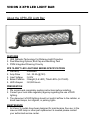
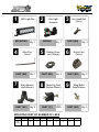
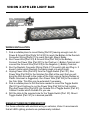
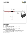
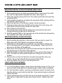
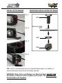
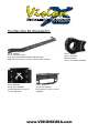
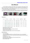
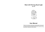
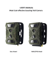
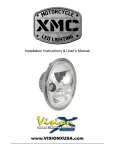
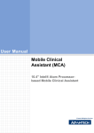
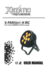
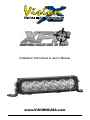
Global Lighting
Lighting Systems
Systems
Global
visionxusa.com
Installation Instructions & User’s Manual
www.VISIONXUSA.com
VISION X XPR LED LIGHT BAR
About the XPR LED Light Bar:
FEATURES
1. IRIS Reflector Technology For Distance Light Projection
2. Dual Mounting Options; End Cap and Mounting Feet
3. PWM Integrated Dimming Circuitry
XPR 10-WATT LED LIGHT BAR SERIES SPECIFICATIONS
1. Warranty
: Extended
2. Amp Draw
: 5A - 22.5A (@12V)
3. Input Voltage
: 9-32V
4. Beam Patterns : Straight (3-6 LED), Tilted LED’s (9-27 LED)
5. LED Lifespan : 50,000 Hours
PREPARATION
1. We recommend completely reading instructions before installing.
2. Consult your local state regulatory agency regarding the use of LED
lighting.
3. The placement of LED lighting should not restrict airflow to the radiator, or
block head lamps, turn signals, or parking lights.
MAINTENANCE
1. All Vision X models have been designed for maintenance free use. In the
case an LED lamp or other part replacement is needed please contact
your authorized service center.
Global Lighting
Lighting Systems
Systems
Global
visionxusa.com
1
MOUNTING
4
5
8
Wing Mounts
(Side Mount)
PART (W1)
6
9
QTY
Varies
Qty: 2
Wing Bolts/
Nuts/Washer
PART (W3)
MOUNTING FEET BY NUMBER OF LEDS
# of
Feet
Qty: 2
Nylock Nut
(5mm)
PART (M3)
Qty: 4
Mounting Feet
(Bottom Mount)
PART (F1)
Qty: 2
Hex Head Bolt
(5mm)
PART (M1)
Qty: 1
Rubber Grommet (Wings)
PART (W2)
Qty: 1
3
One Light
Harness
WIRING
Qty: 1
Allen Key
(5mm)
PART (M5)
7
2
LED Light Bar
3LED
6LED
9LED
12LED
15LED
18LED
21LED
24LED
27LED
1
2
3
4
5
5
6
6
7
Qty: 4
VISION X XPR LED LIGHT BAR
WIRING INSTALLATION
1. Find a suitable place to mount Relay [Part R1] leaving enough room for
Power & Ground Wire [Parts W1 & W2] to reach the Battery & the Deutsch
Connector Wiring [Parts C1] to reach the Light. Mount Relay.
2. Run Power Wire [Part W1] & Ground Wire [Part W2] to the Battery.
Connect the Power Wire [Part W1] to the Positive (+) Battery Terminal and
connect the Ground Wire [Part W2] to the Negative (-) Battery Terminal.
3. Run the Deutsch Connector Wiring [Parts C1] to each Light and Plug in. It
doesn’t matter which Deutsch Connector plugs into which Light.
4. Unplug Power Wire [Part W3] from the Toggle Switch [Part S1]. Run
Power Wire [Part W3] to the Vehicles Fire Wall at the point that you will
bring the Wire through to the inside of the Cab (using a Factory Rubber or
Plastic Grommet is suggested). Run Power Wire [Part W3] to the inside of
the Cab. Note: This Wire can be extended if necessary.
5. Find a suitable place to Drill the Hole needed to mount the Toggle Switch
[Part S1] and Continue to run the Power Wire [Part W3] to that location.
Plug the Power Wire [Part W3] into Outside Pin of Toggle Switch [Part S1].
It doesn’t matter which Outside Pin you use.
6. Drill the Hole to the required size for the Toggle Switch [Part S1]. Mount
Toggle Switch [Part S1] to in desired position.
MANUFACTURER RECOMMENDATION
For those unfamiliar with electrical wiring on vehicles, Vision X recommends
that all LED Lighting products are professionally installed.
Global Lighting
Lighting Systems
Systems
Global
visionxusa.com
(R1)
(W2)
(S1)
(W3)
(W1)
(C1)
COMPONENTS KEY
Part (R1) Relay
Part (W1) Power Wire for Relay Coil
a. 12 Volt Negative (-) Input Wire for Relay Pin 86
Part (W2) Ground Wire for Relay Coil
a. 12 Volt Positive (+) Input Wire for Relay Pin 30
Parts (C1) Deutsch Connectors for Lights
a. Attached to12 Volt Positive (+) Power Wires for Relay Pin 87
Part (W3) Power Wire for Relay Input
a.12 Volt Positive (+) Input Wire for Relay Pin 85 [Part R1]
Part (S1) Toggle Switch
VISION X XPR LED LIGHT BAR
MOUNTING INSTALLATION FOR WINGS (END CAPS)
1. Start by placing two (2) rubber grommets [W2] on each side of the LED
bar over the appropriate threaded bolt holes. (See Figure 1)
2. Place the mounting wings [W1] over the rubber grommets and insert the
wing bolts [W3].
3. Use a phillips screwdriver to tighten the wing bolts [W3], starting with the
top bolt first. (See Figure 2)
4. Place the light bar on the location where it will be mounted.
5. Determine where the 5mm bolt [M1] will be placed for each wing, and
mark where the bolt location will be for each side.
6. Drill a hole for the 5mm bolt.
7. Line the light bar wings over the drilled hole and slide the 5mm bolt
through the wing as well as the drilled hole.
8. Slide the washer [M2] on the opposite side of the drilled hole followed by
the nut [M3], and screw until secured.
MOUNTING INSTALLATION FOR FEET
1. Start by setting the light bar in the location that you plan to mount it in.
Mark each end of the light bar and measure the length.
2. Depending on the length of your light bar, you will have a certain number of mounting feet [F1] included in the packaging. These feet fit into
grooves on the back of the light bar.
3. Place each mounting feet [F1] (with bolt head pointing into light bar) into
the feet grooves on the back of the light bar.
4. Mark the location of each mounting feet on your vehicle. Drill holes for
each. The feet can slide inside the grooves, letting you fine tune the
location.
5. Remove the nut from the feet bolt, and place the light bar onto your
vehicle, line up the bolts with the previously drilled holes.
6. Securely tighten the nut to the mounting feet bolt.
LIGHT ANGLE ADJUSTMENT
1. For the Wing Mount option, simply loosen the bottom wing nut (Fig. 4) on
each end and rotate light bar to desired angle. Fasten when completed.
2. For the Feet Mount option, use the provided allen wrench to loosen both
the Allen bolts on each side the light bar. Once desired angle is achieved,
tighten the bolts.
3. A good reference point is at 20 ft; the top of the beam should be 3” down
from center of light (with the light bar at dead center). Tighten light and
enjoy.
Global Lighting
Lighting Systems
Systems
Global
visionxusa.com
INSTALLATION IMAGES
MOUNTING INSTALLATION FOR WINGS
Fig. 1
(M1)
Fig. 2
Mounting Wing
(W1)
(M2)
Fig. 3
(M3)
Fig. 4
TIP: Vision X recommends the use of liquid thread-locker, or Locktite, to
ensure that every bolt and nut are safely secured.
WARNING: Bolts, Nuts, and Washers are Stainless Steel. DO NOT USE
Pneumatic or Electric Tools to Tighten and Loosen. The Hardware Will
Permanently Lock Together.
Global Lighting
Lighting Systems
Systems
Global
visionxusa.com
You May Also Be Interested In:
Part # - 9890975
Item # - XIL-OEH0713JK
Jeep JK Vehicle Specific Hood Mount Bracket (visit
www.visionxusa.com for a full list of vehicle specific products)
Part # - 4000308
Item # - XIL-LICENSEP
License Plate Mount For Up To
12” LED Light Bars.
Part # - 4006522
Item # - XIL-B150
Billet Tube Mount
(0.75”-2.0” Diameter Available)
Part # - 9892313
Item # - XIL-WINCH6
Winch Mount For Up To 12” LED
Light Bars
www.VISIONXUSA.com