1
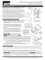
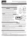
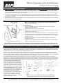
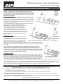
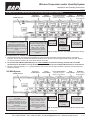
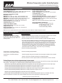
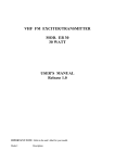
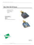
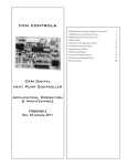
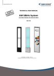
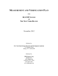
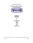
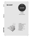
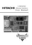
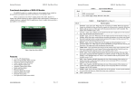
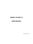
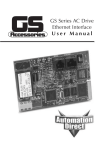
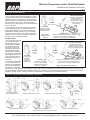
Wireless Temperature and/or Humidity System
Installation and Operating Instructions
rev. 04/21/15
27986_Wireless_System_Ins
Wireless System Overview
418 MHz System:
The Transmitter measures the temperature or temp/
humidity and transmits the data at 418MHz to the 418
MHz Receiver up to 100 feet away. The optional temperature setpoint and override status are also transmitted at 418 MHz to the receiver. The transmit rate is
about once every 20 seconds with an estimated battery
life of 5 to 8 years.
The information sent by the Transmitter is picked up
by the 418 MHz Receiver and passed along to the
Analog Output Modules. Each transmitted variable
(temperature, humidity, setpoint, etc.) is converted by
a separate output module into an analog resistance,
voltage, current or relay contact which is hard wired to
the analog inputs of the BAS controller.
Analog Output Modules
Converts the Temperature,
Humidity, Setpoint and
Override Info into an
analog resistance, voltage,
current or relay for the
BAS controller
418 MHz
Up to 100 Feet
Transmitter
Transmits the Temp,
Humidity, Setpoint
and Override Info
Fig. 1: 418
MHz Wireless
System
418 MHz Receiver
Receives the Temperature, Humidity, Setpoint
and Override Info from the Transmitter and
passes it on to the Analog Output Modules
900 MHz System:
The Transmitter measures
Analog Output Modules
the room temperature or
Converts the Temperature,
temp/humidity and transHumidity, Setpoint and
mits the data at 418MHz
Override Info into an analog
to a Repeater up to 100
resistance, voltage, current
feet away. The optional
or relay for the BAS controller
temperature setpoint and
override status are also
900 MHz
418 MHz
transmitted at 418 MHz to
Up to 1,000
Up to 100
the Repeater. The transmit
Feet
Feet
rate is approximately once
Transmitter
every 20 seconds with an
Transmits the
estimated battery life of 5
Temperature,
900 MHz Receiver
to 8 years.
Humidity,
Receives the Temperature, Humidity, Setpoint
Repeater
Setpoint and
and Override Info from the Repeater and
The 418 MHz information
Receives the 418 MHz
Override Info
passes it on to the Analog Output Modules
sent by the Transmitter is
Info from the Transmitter
and Re-Transmits it at 900
picked up by the Repeater
Fig. 2: 900 MHz Wireless System
MHz up to 1,000 feet
and then Re-Transmitted
at 900 MHz to a 900 MHz
Receiver up to 1,000 feet away. The 900 MHz receiver picks up the information from the repeater and then passes it along to the Analog Output Modules. Each transmitted variable (temperature, humidity, etc.) is converted by a separate output module into an analog
resistance, voltage, current or relay contact which is hard wired to the analog inputs of the BAS controller.
Wireless Temperature and/or Humidity Transmitters
Room Temperature or
Temp/Humidity Sensor
Outside Air Temperature Sensor
Duct Temperature Sensor
Outside Air Temp/Humidity Sensor
Duct Temp/Humidity Sensor
Remote
Temperature
Sensor
Immersion Temperature Sensor
Specifications subject to change without notice.
Building Automation Products, Inc., 750 North Royal Avenue, Gays Mills, WI 54631 USA
Tel:+1-608-735-4800 • Fax+1-608-735-4804 • E-mail:[email protected] • Web:www.bapihvac.com
1 of 8
Wireless Temperature and/or Humidity System
Installation and Operating Instructions
rev. 04/21/15
27986_Wireless_System_Ins
Analog Output Module Training
The installation process requires that each transmitter is trained to its associated output modules so that they communicate with each other. Pushing
buttons in a defined sequence on the units will bind them together.
The training process is easiest on a test bench with the units within arm’s
reach of each other. Training can be done in the field but requires two people
and a set of walkie talkies or cell phones. Be sure to place an identification
mark on the transmitter and associated output modules after they have been
trained so that they can be matched together at the job site.
Battery polarity is
important or damage
to the unit may occur
Override
Button
If more than one variable is transmitted by the transmitter (temperature,
humidity and setpoint for instance), each variable requires a separate output
module. Perform the training sequence for each output module. Any transmitted variable can be trained to more than one output module. If a Repeater
is used in the system, be sure it is powered and within reception range of the
transmitter and the 900 MHz Receiver to train the output modules.
Setpoint
Slider
TEMPERATURE OR HUMIDITY VARIABLE TRAINING
1. To train an output module to a temperature or humidity variable, select the
Resistance, Voltage or Current Output Module calibrated to the proper
temperature or humidity range and connect it to the wireless receiver.
Note: Multiple output modules can be trained to the same transmitter
variable if desired.
2. Apply power to the receiver which will supply power to the
connected output modules. The power LED on the receiver
will light and remain lit. (Current Output Modules must have
loop power supplied to the module itself before they can
be trained.)
3. Remove the cover of the room transmitter and remove the
battery tabs or install the batteries, observing polarity as
shown in Fig 3. Or open the cover of the BAPI-Box on nonroom transmitters and remove the battery tabs or install the
batteries as shown in Fig 4. The “transmit LED” will flash
about once every 20 seconds, indicating a transmission. (The
flash is very quick.)
Training
Button
Transmit
LED
Fig. 3:
Room Transmitter battery
installation and training
Training Button
Transmit LED
Battery
Connectors
Transmitter Module
Fig. 4:
Non-Room Transmitter
battery installation and
training. (Duct Temp/
Humidity Transmitter is
shown but the process
is similar for all nonroom transmitters.)
4. Press and hold down the “Service Button” on the top of the
output module (Fig 5) that you wish to train. Then, press
and release the “training button” (see Fig 3 & Fig 4) on the
transmitter. When the output module receives the “training
transmission” from the transmitter, the output module’s red LED will light steady. Release the
“Service Button” on the output module and the red LED will go out. The transmitter and output
module are now trained to each other. During normal operation, the output module’s LED will
flash about once every 20 seconds indicating data reception from the transmitter trained to it.
Note: Combination transmitters send both the temperature and humidity information when the
“Training Button” is pressed. However, each Analog Output Module is configured at
the time of order as a temperature, humidity, setpoint or override module and will only
recognize the relevant information and will ignore the rest.
5. Mount the transmitter at the desired location, removing the batteries if needed. (The units will
remain trained to one another through power failures and battery replacement.)
SETPOINT VARIABLE TRAINING
Battery
polarity is
important
or damage
to the unit
may occur.
Output
Module
Service
Button
Fig. 5:
Output
Module
1. To train an output module to a Setpoint variable, select the Setpoint Output Module (SOM) calibrated to the proper setpoint range
and connect it to the wireless receiver. Note: Multiple output modules can be trained to the same transmitter variable if desired.
2. Apply power to the receiver which will supply power to the connected output modules. The LED on the Receiver will light and remain
lit.
3. Remove the cover of the room transmitter and remove the battery tabs or install the batteries, observing polarity as shown in Fig 3.
The “transmit LED” will flash about once every 20 seconds, indicating a transmission. (The flash is very quick.)
4. Press and hold down the “Service Button” on the top of the output module (Fig 5). Then, press and release the OVERRIDE button
on the transmitter (See Fig 3). (Note: If the unit was not ordered with an override function, then the OVERRIDE button will be
shorter and will not extend outside the case but will still be accessible upon removing the cover.) When the output module receives
the “Training Setpoint” info from the transmitter, the output module’s red LED will light. Release the “Service Button” on the output
Continued on next page....
Specifications subject to change without notice.
Building Automation Products, Inc., 750 North Royal Avenue, Gays Mills, WI 54631 USA
Tel:+1-608-735-4800 • Fax+1-608-735-4804 • E-mail:[email protected] • Web:www.bapihvac.com
2 of 8
Wireless Temperature and/or Humidity System
Installation and Operating Instructions
rev. 04/21/15
27986_Wireless_System_Ins
Analog Output Module Training continued....
module and the red LED will go out. The transmitter and output module are now trained to each other. During normal operation, the
output module’s LED will flash about once every 20 seconds indicating data reception from the transmitter trained to it.
5. Mount the transmitter at the desired location, removing the batteries if needed. (The units
will remain trained to one another through power failures and battery replacement.)
OVERRIDE TRAINING - OVERRIDE IN PARALLEL WITH THE TEMP VARIABLE
1. An Override function can be added to a Resistance Output Module or Voltage Output
Module that has been previously trained to the Temperature variable. (Current Output
Modules cannot be used with the override function.) Select the previously trained
output module that will have the override function. Remove the cover by squeezing
the top and bottom or using a flat screwdriver as shown in Fig 6. Place the module’s
jumper J4 in the “Override Training ON” position as shown in Fig 7.
Squeeze
2. Apply power to the receiver which will supply power to the connected output
modules. The power LED on the Receiver will light and remain lit.
3. Remove the room transmitter cover and remove the battery tabs or install the
batteries, observing polarity as shown in Fig 3. The “transmit LED” will flash about
once every 20 seconds, indicating a transmission. (The flash is very quick.)
Squeeze
4. Press and hold down the “Service Button” on the top of the output module (or on
the circuit board if the cover is removed, see Fig 7). Then, press and release the
OVERRIDE button on the room transmitter (See. Fig 3). When the output module receives
the “Training Override” info from the transmitter, the output module’s red LED will light.
Release the “Service Button” on the output module and the red LED will go out. This module
is now trained to the override function on the room transmitter.
5. Return the jumper on J4 to the “Override Training OFF” position
(Fig 7) and replace the output module’s cover. Pressing the override
on the room transmitter will cause the Resistance Output Module
output to go to less than 100 Ohms for 5 seconds or the Voltage
Output Module output to go to 0 Volts for 5 seconds.
6. To remove the override function, retrain the module to the
temperature variable (pg 2). This removes the override function.
7. Mount the transmitter at the desired location, removing the batteries
if needed. (The units will remain trained to one another through
power failures and battery replacement.)
J4 Override
Training Off
Fig. 6:
Cover Removal Squeeze top and
bottom or use a
flat screwdriver.
J4 Override
Training On
“Service Button”
with Cover Off
Fig. 7: Override Training Jumper
Positions (J4) and “Service Button”
OVERRIDE TRAINING - OVERRIDE IN PARALLEL WITH THE HUMIDITY VARIABLE
1. An Override function can be added to a Voltage Output Module that has been previously trained to the Humidity variable. (Current
Output Modules cannot be used with the override function.)
2. Apply power to the receiver which will supply power to the connected output modules. The power LED on the Receiver will light steady.
3. Remove the room transmitter cover and remove the battery tabs or install the batteries, observing polarity as shown in Fig 3. The
small LED at the bottom right of the circuit board, next to the setpoint, will flash approximately once every 20 seconds indicating a
transmission. (The flash is very quick.)
4. Press and hold down the “Service Button” on the top of the Voltage Output Module. Then, press and release the OVERRIDE button
on the room transmitter (See. Fig 3). When the output module receives the “Training Override” info from the room transmitter, the
output module’s red LED will light. Release the “Service Button” on the output module and the red LED will go out. This output
module is now trained to the override function on the room transmitter Pressing the override button on the room transmitter will
cause the Voltage Output Module output to go to 0 Volts for 5 seconds.
5. To remove the override function, retrain the module to the humidity variable. This removes the override function.
6. Mount the transmitter at the desired location, removing the batteries if needed. (The units will remain trained to one another through
power failures and battery replacement.)
OVERRIDE TRAINING - OVERRIDE AS A SEPARATE OUTPUT WITH A RELAY OUTPUT MODULE (RYOM MODEL ONLY)
1. To train a Relay Output Module (RYOM model only) to the Override function, connect the output module to the receiver.
2. Apply power to the receiver which will supply power to the connected output modules. The power LED on the Receiver will light and
remain lit.
3. Remove the room transmitter cover and remove the battery tabs or install the batteries, observing polarity as shown in Fig 3. The
small LED at the bottom right of the circuit board, next to the setpoint (see Fig 3), will flash approximately once every 20 seconds
indicating a transmission. (The flash is very quick.)
Continued on next page....
Specifications subject to change without notice.
Building Automation Products, Inc., 750 North Royal Avenue, Gays Mills, WI 54631 USA
Tel:+1-608-735-4800 • Fax+1-608-735-4804 • E-mail:[email protected] • Web:www.bapihvac.com
3 of 8
Wireless Temperature and/or Humidity System
Installation and Operating Instructions
rev. 04/21/15
27986_Wireless_System_Ins
Analog Output Module Training continued....
4. Press and hold down the “Service Button” on the Relay Output Module (Fig 5). Then, press and release the OVERRIDE button on
the room transmitter. When the output module receives the “Training Override” info from the room transmitter, the output module’s
red LED will light. Release the “Service Button” on the output module and the red LED will go out. This Relay Output Module is now
trained to the override function on the room transmitter.
5. Pressing the override button on the room transmitter will cause the output of a “Momentary” Relay Output Module to switch states
for 5 seconds — the output of a “normally open” version will go to closed for 5 seconds, the output of a “normally closed” version will
go to open for 5 seconds.
6. Mount the transmitter at the desired location, removing the batteries if needed. (The units will remain trained to one another through
power failures and battery replacement.)
Mounting of the Room Transmitter
Note: The transmitter should have been trained to the output module at
this point of the installation.
Provided Drywall
Anchors
Provided #6 x 1” Screws
3.25”
(80mm)
Fig. 8: Drywall Mounting
Drywall Mounting
1. Place the base plate against the wall where you want to mount the sensor.
Typically 5 feet above the floor.
2. Using a pencil, mark out the two mounting holes.
3. Drill two 3/16” (4.7 mm) holes in the center of each marked mounting hole. Insert a
drywall anchor into each hole.
4. Secure the base to the drywall anchors using the #6 x 1” mounting screws provided.
5. Install provided batteries or pull battery tabs and follow polarity as shown in figure
3 or damage may occur. The unit will work on just one battery however the battery
life will be cut in half.
6. Attach cover by latching it to the top of the base, rotating the cover down and
snapping it into place.
7. Secure the cover by backing out the lock-down screws using a 1/16” Allen wrench
until they are flush with the bottom of the cover.
Note: Mounting of Non-Room Transmitters is covered in the individual installation and Operation documents for that unit.
Go to the specific wireless transmitter product on the BAPI website (www.bapihvac.com) and click on the “documents” tab.
Mounting and Locating of the Antennas on the 418 MHz Receiver, 900 MHz Receiver and the Repeater
The 418 MHz Receiver, 900 MHz Receiver and Repeater may be located inside a metal enclosure but their antennas must be outside
the enclosure. The 418 MHz Receiver comes with a 418 MHz Dipole Antenna. The 900 MHz Receiver comes standard with a 900 MHz
“Whip” Antenna but is available with a 900 MHz Dipole Antenna. The Repeater comes standard with a 418 MHz Dipole Antenna and a
900 MHz “Whip” Antenna, but is available with a 900 MHz Dipole Antenna.
To mount the 418 MHz Dipole Antenna or 900 MHz Dipole Antenna, peal off the protective film from the adhesive pad and stick the
antenna to a wall or other non-metallic support so that antenna is vertical for best reception. Antenna’s should be mounted as far away
from metal plates or bars as possible to avoid RF energy being reflected back or blocked on the other side of the metal. An antenna will
not work inside a metal box. Mounting to drywall between studs, ceiling tiles, brick, or concrete is very common.
Transmission distance performance will vary based on environment. 100 feet is the maximum that can be expected if there are no
obstructions. In general, each obstruction will half the expected transmission distance. Obstructions include but are not limited to; walls,
partitions, floors, ceilings, doors, tinted glass, ground, many people, vehicles, foliage, rain, snow and fog. Metal (solid or screen) blocks
the RF signal preventing propagation but also can bounce the signal around the potential obstacle. Wood, drywall, plaster, brick, and
concrete attenuates the signal but will let it
pass (if it’s not too thick) at a reduced signal
strength. Anything that holds water absorbs
the signal to the point of blockage like rain, fog,
people, ground, dense foliage etc. Elevator
shafts and stairwells usually block RF signals.
900 MHz
The 900 MHz “Whip” Antenna simply screws
“Whip”
onto the 900 MHz Receiver or the Repeater.
Antenna
900 MHz
418 MHz
Mounting the antenna on a metal surface may
Dipole
Dipole
limit reception from behind the surface.
Antenna
Antenna
For more information on mounting antennas,
see the BAPI docs “18709_ins_418_433_
antenna.pdf” and “19858_ins_900_MHz_
antenna.pdf” which are available on the BAPI
Note: The Dipole antennas above are displayed horizontally to show
website at www.bapihvac.com.
dimensions but they should be mounted vertically for best reception.
Specifications subject to change without notice.
Building Automation Products, Inc., 750 North Royal Avenue, Gays Mills, WI 54631 USA
Tel:+1-608-735-4800 • Fax+1-608-735-4804 • E-mail:[email protected] • Web:www.bapihvac.com
4 of 8
Wireless Temperature and/or Humidity System
Installation and Operating Instructions
rev. 04/21/15
27986_Wireless_System_Ins
Mounting of the 418 MHz Receiver, 900 MHz Receiver, Repeater and Analog Output Modules
The 418 MHz Receiver, 900 MHz Receiver, Repeater and Analog Output
Modules can be mounted in snap track, DIN Rail or surface mounted.
The text and figures in this section refer to the 418 MHz Receiver, but the
mounting process is the same for the 900 MHz Receiver and the Repeater
(although there are no Analog Output Modules connected to the Repeater).
Fig. 9:
Receiver
and output
modules
mounted in
snaptrack.
SNAPTRACK MOUNTING
Push in the blue mounting tabs on the bottom of the receiver and output
modules. These units will now fit into the board slots of 2.75” snap track.
Insert the receiver at the far left of the snap track, then insert each analog
output module and slide it to the left until its connectors are fully mated into
the receiver or the next analog output module. You may attach up to 127
analog output modules to a receiver.
If your output modules cannot fit in one piece of snap track, then mount
another piece of snap track nearby and insert the
additional modules. Connect wires from the right side
of the first string of modules to the left side of the
second string of modules on the second snap track.
(See “Extending the RS485 Network...” on pg. 7.) This
configuration requires one or more Pluggable Terminal
Block Connector Kits (BA/AOM-CONN) for the extra wire
terminations on the left and right side of the Analog Output
Modules. Each kit includes 4 connectors for the left and
right connections.
DIN RAIL MOUNTING
Push out the blue mounting tabs on the bottom of the
receiver and output modules. These units will now snap
onto DIN Rail. Catch the EZ mount hook on the edge of
the DIN rail as shown in Fig 11. Then rotate into place.
Fig. 10:
Receiver and output modules mounted on DIN Rail.
Fig. 11:
Catch the EZ Mount
hook on the edge of
the DIN Rail, then
rotate into place.
Attach the receiver at the far left of the DIN Rail, then
attach each analog output module and slide it to the left until its connectors are fully mated into
the receiver or the next analog output module. You may attach up to 127 analog output modules
to a receiver.
If your output modules cannot fit onto one piece of DIN Rail, then mount another piece
nearby and attach your additional modules. Connect wires from the right side of the first
string of modules to the left side of the second string of modules on the second DIN Rail. This
configuration requires one or more Pluggable Terminal Block Connector Kits (BA/AOM-CONN)
for the extra wire terminations on the left and right side of the Analog Output Modules. Each kit
includes 4 connectors for the left and right connections.
SURFACE MOUNTING
Push out the blue mounting tabs on the bottom of the receiver and output modules. Attach the
receiver to the surface by inserting a screw in each blue tab. Attach Analog Output Modules by
placing each one against the surface and sliding it to the left until its connectors are fully mated
into the receiver or the next analog output module. Attach each module to the surface with two
screws, one in each blue tab. You may attach up to 127 analog output modules to a receiver.
Fig. 12: Receiver and output
modules surface mounted.
If your output modules cannot fit in one straight line on the surface, then mount a second string of modules nearby. Connect wires from
the right side of the first string of modules to the left side of the second string of modules. (See “Extending the RS485 Network...” on pg.
7.) This configuration requires one or more Pluggable Terminal Block Connector Kits (BA/AOM-CONN) for the extra terminations on the
left and right side of the Analog Output Modules. Each kit includes 4 connectors for the left and right connections
FCC Approval and Compliance
FCC Approval #: T4F061213RSO (418MHz Room Transmitter Only) • T4F060811TEMP (418MHz Temperature Probe Only)
T4F060811RH (418MHz Temp & Humidity Probe Only) • MCQ-XBPS3B (Repeater Unit Only)
Compliance: This device complies with Part 15 of the FCC rules Operation is subject to the following conditions.
1. This device may not cause harmful interference.
2. This device must accept any interference received, including interference that may cause undesired operation.
FCC Radio Frequency Interference Statement:
This equipment has been tested and found to comply with the limits for a Class B digital device, pursuant to Part 15, Subpart B, of
the FCC Rules. This equipment generates, uses, and can radiate radio frequency energy. If not installed and used in accordance with
the instructions, it may cause interference to radio communications.
Specifications subject to change without notice.
Building Automation Products, Inc., 750 North Royal Avenue, Gays Mills, WI 54631 USA
Tel:+1-608-735-4800 • Fax+1-608-735-4804 • E-mail:[email protected] • Web:www.bapihvac.com
5 of 8
Wireless Temperature and/or Humidity System
Installation and Operating Instructions
rev. 04/21/15
27986_Wireless_System_Ins
418 MHz Receiver and 900 MHz Receiver with Analog Output Modules Termination
418 MHz System
418 MHz Receiver
System Power Supply
9 to 30VDC or 17 to 31VAC
Power for the Power Bus can be
supplied to the receiver or to the
Analog Output Module on the far right
of the string of modules, but not to both
places.
The Power Bus must be connected to
the controller “-” power terminal.
Resistance
Output Module
Voltage
Output Module
The Resistive Thermistor Temp.
Signal is Polarity Sensitive to the
Controller and Must Have Less
than a 5VDC Bias Voltage.
Both “+” and “-” must be
connected to the controller
signal input and the negative “-”
connected to the power supply
negative “-”
Current Output Module
Requires loop power
before it can be trained.
0 to 5VDC or
0 to 10VDC
Analog Signal
Relay
RS-485 Bus
Output Module To Other Analog
Output Modules
Current Loop
Power
Supply
9 to 36VDC
4 to 20mA Current
Loop Signal to the
Controller
Solid State Relay
40 VAC/VDC Max
150 mA Max
1 uA Leakage Max
Fig 13: 418 MHz Receiver and Output Module System Wiring
Termination Notes for 418 MHz and 900 MHz Systems:
1. The wireless receiver and Analog Output Modules are interconnected and require module power along the “Power Bus”
terminals. The bus can be powered from either the receiver end on the left or the last output module on the right side. Be sure
you have enough DC current or AC VA for all the devices on the bus.
2. The Current Output Module (BA/COM) signal is LOOP POWERED and must be externally powered with 9 to 36 VDC
separate from the Power Bus. The Loop Power must be connected to the Current Output Module before it can be trained.
3. Be sure to follow the polarity (+ or –) symbols listed on each receiver and the output modules to maintain communication and
Power Bus integrity.
900 MHz System
900 MHz Receiver
System Power Supply
9 to 15VDC
Power for the Power Bus can be
supplied to the receiver or to the
Analog Output Module on the far right
of the string of modules, but not to
both places.
The Power Bus must be connected to
the controller “-” power terminal.
Resistance
Output Module
Voltage
Output Module
The Resistive Thermistor Temp.
Signal is Polarity Sensitive to the
Controller and Must Have Less
than a 5VDC Bias Voltage.
Both “+” and “-” must be
connected to the controller
signal input and the negative “-”
connected to the power supply
negative “-”
Current Output Module
Requires loop power
before it can be trained.
0 to 5VDC or
0 to 10VDC
Analog Signal
Relay
RS-485 Bus
Output Module To Other Analog
Output Modules
Current Loop
Power
Supply
9 to 36VDC
4 to 20mA Current
Loop Signal to the
Controller
Solid State Relay
40 VAC/VDC Max
150 mA Max
1 uA Leakage Max
Fig. 14: 900 MHz Receiver and Output Module System Wiring
Specifications subject to change without notice.
Building Automation Products, Inc., 750 North Royal Avenue, Gays Mills, WI 54631 USA
Tel:+1-608-735-4800 • Fax+1-608-735-4804 • E-mail:[email protected] • Web:www.bapihvac.com
6 of 8
Wireless Temperature and/or Humidity System
Installation and Operating Instructions
rev. 04/21/15
27986_Wireless_System_Ins
Extending the RS485 Network between the Receiver and the Analog Output Modules
The Analog Output Modules may be mounted up to 4,000 feet away from the Receiver. The total length of all the shielded, twisted
pair (TSP) cables shown in Fig. 15 is 4,000 feet (1,220 meters), and “T” taps are not allowed. Connect the terminals as shown in
Fig. 15. BAPI’s VC350A EZ Voltage Converter and a small transformer can be used to power the group of Analog Output Modules.
*If the distance from the receiver to the group of Analog Output Modules is greater than 100 feet (30 meters), provide a separate
power supply for that group of Modules and install a 120Ω load resistor
(1/4 watt) across the “+” and “-” communication terminals.
120Ω load resistor (1/4 watt) across the “+” and “-”
communication terminals. See Asterisk (*) above.
Pluggable Terminal Block
Kit (BA/AOM-CONN)
RS485 TSP Wiring
RS485 TSP Wiring
Y
120Ω*
Note: This
configuration
requires one or
more Pluggable
Terminal Block Kits
for the extra wire
terminations on
the left and right
side of the Analog
Output Modules.
Each kit includes 4
connectors.
Receiver
Analog Output Modules
Analog Output Modules
BAPI
VC350A
EZ Voltage
Converter
BAPI
VC350A
EZ Voltage
Converter
BAPI
VC350A
EZ Voltage
Converter
Transformer
Transformer
Transformer
Fig. 15: Extended RS485 Network between the Receiver and the Analog Output Modules
Specifications
WIRELESS TRANSMITTER SPECS
WIRELESS 418MHZ & 900 MHZ RECEIVER SPECS
Supply Power: Two AA 3.6V Lith. batteries, 2.25 AH
5 to 8 year battery life at 20 second transmit rate
Supply Power:
418 MHz Unit: 9 to 30 VDC or 17 to 31 VAC
900 MHz Unit: 9 to 15 VDC
Potential Inputs:
Temperature - Thermistor • Relative Humidity – Capacitive
Setpoint – Potentiometer • Override – SPST switch
Accuracy: ±0.54°F (±0.3°C) / ±2% RH
Transmitted Range: -40 to 185°F (-40 to 85°C ) • 0 to 100% RH
Antenna: Built inside the enclosure
Power Consumption: 80 mA max. DC, .5 VA max AC
Inputs: 418MHz or 900 MHz (depending on model)
Input Sensitivity: -112db
Output Signal: RS485 Proprietary
Indicators: Red Power LED, blinks during reception
Dimensions: Shown at the bottom of page 1
Antenna:
418 MHz Unit: 418 MHz Dipole with 79” Cable
900 MHz Unit: 900 MHz Whip or 900 MHz Dipole w/ 79” Cable
Environmental Operation Range:
Temp: 32° to 140°F (0° to 60°C)
Humidity: 5% to 95% RH non-condensing
Enclosure Material & Rating: ABS Plastic, UL94 V-0
Radio Frequency: 418 MHz North America
Typical Reception:
418 MHz Unit: Up to 100 feet in building, line of sight
900 MHz Unit: Up to 1,000 feet in building
Bus Cable Distance:
4,000 ft with shielded, twisted pair cable
(Belden 9841, Belden 8132 or equivalent)
Transmitter Interval: ~20 seconds
WIRELESS REPEATER SPECS
Supply Power: 9 to 15 VDC
Power Consumption: 150 mA max. DC
Input and Output: 418 MHz Input, 900 MHz Output
Dimensions: 3.32” W x 2.87” L x 1.28”H (84.3 x 98.2 x 32.5mm)
Environmental Operation Range:
Temp: 32 to 140°F (0 to 60°C)
Humidity: 5% to 95% RH non-condensing
Enclosure Material & Rating: ABS Plastic, UL94 V-0
Output Modules per Receiver: Any mix of up to 127
Overall Dimensions: 3.32” W x 2.87” L x 1.28”H
(84.3 x 98.2 x 32.5mm)
Environmental Operation Range:
Temp: 32°F to 140°F (0°C to 60°C)
Humidity: 5% to 95% RH non-condensing
Enclosure Material and Rating: ABS Plastic, UL94, V-0
Specifications subject to change without notice.
Building Automation Products, Inc., 750 North Royal Avenue, Gays Mills, WI 54631 USA
Tel:+1-608-735-4800 • Fax+1-608-735-4804 • E-mail:[email protected] • Web:www.bapihvac.com
7 of 8
Wireless Temperature and/or Humidity System
Installation and Operating Instructions
rev. 04/21/15
27986_Wireless_System_Ins
Analog Output Module Specifications
All Analog Output Modules:
Overall Dimensions: 2.5”H x 2”W x 1.25”D, (63.5 x 49 x 31.7mm)
Enclosure Material & Rating: ABS Plastic, UL94 V-0
Resistance Output Module (ROM):
Resolution: ~0.5ºF
ROM-102: 35 to 120ºF (1 to 50ºC), 10K-2 Thermistor Curve
ROM-103: 32 to 120ºF (0 to 50ºC), 10K-3 Thermistor Curve
ROM-10311: 32 to 120ºF (0 to 50ºC), 10K-3 (11K) Therm. Curve
ROM-20: 53 to 120ºF (12 to 50ºC), 20K Thermistor Curve
Power Consumption: 11.9 mA max. DC, .36 VA max AC
Thermistor Bias: Less than 5 VDC max
Output Resolution: 10 bit
Voltage Output Module (VOM):
Output Voltage Range: 0 to 5 volts or 0 to 10 Volts
Output Current: 1 mA
Power Consumption: 11.9 mA max. DC, .36 VA max AC
Output Resolution: 10 bit
Setpoint Output Module (SOM):
Setpoint Output Ranges: See data sheet
Power Consumption: 11.9 mA max. DC, .36 VA max AC
Output Resolution: 10 bit
Current Output Module (COM):
External Loop Power Required: 9 to 36VDC at 25mA min
Output Current Range: 4 to 20 mA (factory calibrated)
Supply Bus Power: Not used by module just feeds through
Output Resolution: 12 bit
Note: Loop must be powered to train the output module.
Relay Output Module (RYOM Only):
Relay Output: 40V (DC or AC peak), 150 mA max.
Off state leakage current 1 uA max.
On state resistance 15Ω max.
5 second momentary actuation
Note: Full device specifications are on the individual Analog Output Module installation/operation sheets.
Wireless System Diagnostics
Possible Problems:
Temperature or Humidity is reading
its low limit or high limit, or the LED at
the top of the Analog Output Module is
blinking rapidly:
Possible Solutions:
- Check for proper wiring and connections from the output modules to the controller.
- Check to see if the controller’s software is configured properly.
- Check for proper power to the receiver, repeater (if used) and output modules.
- Check that the associated transmitter is transmitting (the LED will flash about
once every 20 seconds when it transmits). If not, replace the batteries. Check
that the associated receiver is receiving the tranmissions (its LED will blink right
after the transmitter LED if it receives that transmission.) If it is not receiving
the transmissions, move it closer to the transmitter or reposition the antenna
for maximum reception. Note: The receiver will receive transmissions from all
transmitters that are within range, not just the one you are testing.
- Retrain the Analog Output Module.
Temperature or Humidity reading is
coming out the wrong output module
- Retrain the Analog Output Module.
Temperature or Humidity reading is
incorrect
- Check for proper wiring and connections from the output modules to the controller.
- Check to see if the controller’s software is configured properly.
- Check to see if the correct output module is connected to the correct controller.
Default Status when wireless transmission is interrupted:
If an output module does not receive data from its assigned transmitter for 15 minutes, the red LED on the top of the module will
blink rapidly. If this happens, the individual Analog Output Modules will react as follows:
• Resistance Output Modules (BA/ROM) calibrated for temperature will output the highest resistance in their output range.
• Voltage Output Modules (BA/VOM) calibrated for temperature will set their output to 0 volts.
• Current Output Modules (BA/COM) calibrated for temperature will set their output to 4 mA.
• Voltage Output Modules (BA/VOM) calibrated for humidity will set their output to their highest voltage (5 or 10 volts).
• Current Output Modules (BA/COM) calibrated for humidity will set their output to 20 mA.
• Setpoint Output Modules (BA/SOM) will hold their last value indefinitely.
• Relay Output Modules (BA/RYOM Units Only) will go to their default state (example: open for a normally open unit).
When a transmission is received, the output modules will revert to normal operation in 60 seconds or less.
Specifications subject to change without notice.
Building Automation Products, Inc., 750 North Royal Avenue, Gays Mills, WI 54631 USA
Tel:+1-608-735-4800 • Fax+1-608-735-4804 • E-mail:[email protected] • Web:www.bapihvac.com
8 of 8