1
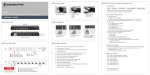
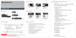
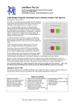
JED MICROPROCESSORS PTY LTD
173 Boronia Rd, Boronia, (PO Box 30), Victoria 3155 Australia
Phone: +61 3 9762 3588,
Fax: +61 3 9762 5499.
http://www.jedmicro.com.au
email: [email protected]
T460R control of a Kramer VP-773/4 via SER1 RS232
Ed Schoell 25th Nov 2014
Introduction
The Kramer VP-773/4 is a powerful switch/scaler which can be controlled via the second serial port on a T460 using strings
manually entered into the T460R’s non-volatile memory. These strings are sent at key points of the T460R On and Off cycle
and enable its integration into a room control system completely transparently to the user.
The user just uses the On/source, Off and Volume Up/Down keys as normal, but the source switching and volume control takes
place in the VP-773/4 instead of in the projector. As per other switcher-based systems, the projector should be told, using the
T460R’s mapping function, to stay on an HDMI channel for all T460R channels … all the switching then takes place in the VP773/4. All audio and video signals are routed to the switcher, and audio volume control then happens in the VP-773/4 as well.
The T460R serial 0 controls the projector at whatever baud rate the projector needs, and serial 1 controls the switcher at 9600
8N1.
Note: To enable the volume range (-80 to +20) T460R version 3.73 or later is needed.
VP-773/4 pre-setup
The protocol needs to be set in the Kramer VP-773/4 “Miscellaneous” menu (last one) under “Protocol” to “Legacy”. This will
need to be done by connecting the unit to a display device via an HDMI cable from the output, and then using the IR remote,
turn on power and press the “Menu” key and observe the on screen setup screen. Select the “Misc” item, then “Protocol” then
“Protocol” then “Legacy”. This sets the communications to 9600 baud ASCII RS232.
The volume control in the VP-773/4 controls the “Output” setting … there is a separate setting for “Input” volume which the
T460R does not adjust. It may be necessary to set this up manually to a suitable level using the second (audio) setting. (The
“Input” level comes set at a default of 0db.)
In the same way, output resolution, etc needs to be set up. All these constants are saved in the VP-773/4 non-volatile memory.
The VP-773/4 takes 40 seconds or so to become fully operational after power-up, so the projector warm-up time should be set
to at least 45 seconds, if it was not already at this value because of projector warmup settings. Use the 5th menu to set this.
The VP-773/4 manual is available from: http://www.kramerus.com/downloads/manuals/vp-773.pdf . The only difference
between the VP-773 and the VP-774 is the addition of SDI input and output on the VP-774. SDI appears in the list of input
command selectable parameters.
VP-773/4 Toggle power problem
Unfortunately, these units do NOT have discrete Power On and Power Off commands. Rather, the only power command is
listed on page 69 of the VP-773/4 manual, where a special set of commands is listed which mimic the remote control and front
panel buttons. This provides is only a toggle command for power On/Off (as most LCD and projector IR remotes also have.
(I.e. One push for On, another press for Off.)
JED is discussion with Kramer in Israel, and they may add discrete power commands to a future software update to the VP773/4. (Interestingly, previous Kramer switchers like the 725 and 728 had such commands.) In the mean-time, the following
code addition does work reliably, but with a little more complexity to set up. (The unit does NOT even have a power state test
that allows the state to be read directly.)
Rev 3.73 of the T460R software now includes a facility to test the power state of the VP-773/4 by sending a read data request
to the unit and detecting the length of the reply. All commands (including data requests) are echoed, even in the power off state,
so it is not just a matter of determining if there is or is not a reply … rather, if the unit is on, the answer is appended to the echo.
To work with this behaviour, a threshold is set longer than the echo, but less than the sum of echo plus answer. This threshold is
T460R control of Kramer VP-773/774 Manual, 25th Nov 2014 Part A © JED Microprocessors Pty Ltd
1
set into location 0BFh. If this location is set to 00h (default) it is assumed that there are discrete Power On strings (set into 070h
up) and Power Off strings (set into 0F0h up).
To use this test system, the Toggle Power command is loaded in the normal format into 070h up, in the VP-773/4,
“Y 0 38 0<CR>” (see following table for macro), and the data request command is put into 0F0h up: “Y 1 631<CR>” (actually
“Get Output Format”). If power is actually On, this is replied to (after the echo). If power is Off, it just echoes the command
with no data. A value of 0Ah into 0BFh activates the test mode, and differentiates between reply lengths.
T460R non-volatile memory setup for second serial port
There are a series of locations in the T460R memory allocated for Ser1 port control. There are locations for Power On/Off,
eight Source Select strings, a Volume Control pre and post strings, mute/blank strings, and discrete locations for baud rate
setting, and volume control constants. These functions are described in detail in the Part A T460R user manual, pages 31 to 34.
Strings are stored in 16-byte blocks, and to allow strings of any form, (including ones containing 00h), the string length is
always specified (in binary) in the first byte, so the actual following maximum string length is 15 bytes.
The non-volatile memory can be loaded in two ways … using just the keyboard on the T460R, using the EPROM Edit function,
or using the Serial Edit function, entered via a pin number (2000.) The commands for this are included in the following.
The commands (S, B, etc) are sent in with data as strings as macros in a program like Docklight. See: http://www.docklight.de/
Load the strings, then send using a key click. The T460R replies to each command as a check of the load. ASCII data can be
sent in as text, and binary data (such as the leading length specifier) can be sent in as two hex digits between < and > characters.
Data format for Docklight (etc) is 38400 baud, 8N1.
Function:
Baud rate: 9600
Byte or string needed:
04Fh to 0Eh
Macros for Docklight:
B<0E>
See table in PartA
Power tog. string
Power test string
Pwr test threshold
String into 070h:<09>Y 0 38 0<0D>
String into 0F0h:<08>Y 1 631<0D>
Char count number into 0BFh:<00A>
S070:<09>Y 0 38 0<0D>
S0F0:<08>Y 1 631<0D>
S0BF:<0A>
Test string finds
current pwr state
Value for test
Config after w/up
String into 1C0h: <00>
S1C0:<00>
Not used, so clear
Ch 1 PC 1
Ch 2 PC 2
Ch 3 Comp Vid.
Ch 4 DisplayPort
Ch 5 HDMI 1
Ch 6 HDMI 2
Ch 7 HDMI 3
Ch 8 HDMI 4
String into 140h:<0B>Y 0 120 11<0D>
String into 150h:<0B>Y 0 120 12<0D>
String into 160h:<0A>Y 0 120 9<0D>
String into 170h:<0B>Y 0 120 16<0D>
String into 180h:<0B>Y 0 120 13<0D>
String into 190h:<0B>Y 0 120 14<0D>
String into 1A0h:<0B>Y 0 120 10<0D>
String into 1B0h:<0B>Y 0 120 15<0D>
S140:<0B>Y 0 120 11<0D>
S150:<0B>Y 0 120 12<0D>
S160:<0A>Y 0 120 9<0D>
S170:<0B>Y 0 120 16<0D>
S180:<0B>Y 0 120 13<0D>
S190:<0B>Y 0 120 14<0D>
S1A0:<0B>Y 0 120 10<0D>
S1B0:<0B>Y 0 120 15<0D>
Vol setup bytes
0CCh: Vol. format 80h, set variable
length decimal with - sign in place
0CDh: Volume increment set to 4
0CEh: Max T460R vol set to 25 (19h)
0CFh: Volume offset set to -80 (B0h)
0D0h: <08>Y 0 212 as lead-in
<01><0D> sets CR as term.
This sets Y 0 212 -80<CR> to
Y 0 212 20<CR> in 25 steps
S0CC:<80><04><19><B0>
S0D0:<08>Y 0 212 <01><0D>
(note space after
“212”)
String into 1E0h:<0A>Y 0 743 1<0D>
String into 1E0h:<0A>Y 0 743 0<0D>
S1E0:<0A>Y 0 743 1<0D>
S1F0:<0A>Y 0 743 0<0D>
\ Needs FlagC =1
/
Volume string
Audio mute On
Audio mute Off
Channel settings
for T460R
channels
Note: When the two volume keys are pressed together to action Picture and sound mute, the projector is blanked
via SER0 RS232, and the sound is muted by a command via SER1 RS232.
Note: The VP-774 has an SDI input. The string to make this, e.g. Ch 4 is: S170:<0B>Y 0 120 17<0D>
T460R control of Kramer VP-773/774 Manual, 25th Nov 2014 Part A © JED Microprocessors Pty Ltd
2