1
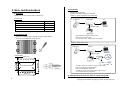
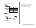
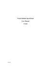
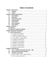
1-3. Dimension
1.Hardware overview
1-1. Port name and function
2
7
1
3
4
5
6
8
#
Name
Function
1
LED (Power)
Power on / off indicator
2
LED (Status)
Status indicator
3
Restart switch
Push to restart device
4
Initialize
switch
Push and hold for 10 seconds to
initialize to factory default
5
Control out
Control signal out for door control or
external alarm /lamp
6
DC-in
DC inlet from AC adapter
7
Ethernet PoE
Connect to Ethernet for IP camera.
PoE power supply is available
8
Wireless
Connect to wireless module
1-2. Connectors
In case of using AC power supply
Connect DC line from AC adapter.
CAUTION
USE ONLY GENUINE AC ADAPTER
Connect DC line
from AC adapter
IP camera
Connect IP camera via Ethernet
In case of using PoE function
Use category 5e or higher cable.
Never connect to AC adaptor.
Connect network
cable from Ethernet
Wireless module
Connect wireless module.
(Optional function)
1
Copyright © 2014 NEC Hong Kong Limited. All right reserved
2. Hardware Specifications
Item
Specification
3. Regulatory Compliance
Remark
Model name
CPT-1000
Size
150.5 x 103.25 x 48.1 mm
Weight
700g
Certifications
UL, CE, CCC
EMC Directive of 2004/108/EC
FCC Part 15, Subpart B: 2012
Operating
conditions
Device; -20~50℃, 10~85% RH
AC adapter; 0~40℃
AC power supply
Using AC adapter
100~240V , 50~60Hz
Power
Consumption
Typical ≦7W
At DC 12V
Ethernet
100BASE-TX,1000BASE-T
RJ-45
PoE
IEEE802.3af Class 1
Default IP address
192.168.2.100
Control signal out
DC 5V
FCC-A Radio Frequency Interference Statement
This equipment has been tested and found to comply with the limits for a class A digital device,
pursuant to part 15 of the FCC rules. These limits are designed to provide reasonable protection
against harmful interference when the equipment is operated in a commercial environment.
This equipment generates, uses, and can radiate frequency energy and, if not installed and used
in accordance with the instruction manual, may cause harmful interference to radio
communications.
Operation of this equipment in a residential area is likely to cause harmful interference,
in which case the user will be required to correct the interference at his personal expense.
Notice 1
The changes or modifications not expressly approved by the party responsible for
compliance could void the user’s authority to operate the equipment.
Notice 2
Shielded interface cables and A.C. power cord, if any, must be used in order to comply with the
emission limits.
4. Safety Precautions
GPIO
Keep this equipment away from humidity.
Place the power cord in such a way that people cannot step on it.
If any of the following situations arises, get the equipment checked by authorized service personnel.
・ The power cord or plug is damaged.
・ Liquid has penetrated into the equipment.
・ The equipment has been exposed to moisture.
・ The equipment has not worked well.
・ The equipment has dropped and damaged.
・ The equipment has obvious sign of breakage.
Do not leave this equipment in an environment unconditioned or in a storage temperature above 60℃.
The equipment may be damaged.
Do not leave this equipment in direct sunlight.
Never pour any liquid into the opening. Liquid can cause damage or electrical shock.
Do not place anything over the power cord.
2
Copyright © 2014 NEC Hong Kong Limited. All right reserved
3) Connecting
5. Basic Install procedure
Connect Ethernet cable.
2 patterns of power supply are available.
Pattern1 : Using PoE (Power over Ethernet)
1) Unpacking
Make sure contents in box (refer contents list )
Contents List
IP camera
Contents
PC
PoE Switch
Quantity
CPT-1000
1
AC adapter (AC cable is not include )
1
Quick Start Guide
1
Hardware Installation Guide
1
Ethernet cable
Appliance
2) Installing to wall
* Use category 5e or higher cable for PoE.
* Never connect power cable.
* For Japanese market, Only pattern 1 is available.
Make sure installing area is enough and near switch device.
Screw up to the wall with these 4 points.
Pattern2 : Using Power cable
IP camera
PC
Switch
Ethernet cable
Drill template
150.5 mm
AC adapter
C6 type
φ7 mm
Screw point (4 points)
103.5 mm
61.3 mm
Appliance
AC cable
> 18 mm
Outline of equipment
* AC cable itself is not included in the product package.
* Connect the DC line from AC adapter.
* USE ONLY GENUINE AC ADAPTER
* AC cable is necessary to satisfy rated voltage ,current,
and complied with local regulation.
142.5 mm
4) Setting and connection test. Refer to “Quick start guide”
3
Copyright © 2014 NEC Hong Kong Limited. All right reserved
5.Optional Install procedure
5-1. GPIO option
5-2. Setting and connection test. Refer to “User Manual”
For both option, Software setting detail is explained in “User Manual”.
It can be downloaded from the NEC Hong Kong website.
1) Pin assignment
Control out pin assignment
1 2 3 4 5
#
Pin assignment
1
Ch1 output DC5V
2
GND
3
Ch2 output DC5V
6 7 8 9
4
GND
Micro D-sub 9
pin
5
NA
6
NA
7
NA
8
NA
9
NA
Usage
http://hk.nec.com/en_HK/solutions/bysolutions/
mobile_facial_recognition_appliance/index.html
White list match
Black list match
2) Connecting
Connect to the external devices or Relay device if necessary.
signal out from appliance is 5V.
Door
Control
Buzzer
Alert
Lamp
Alert
4
Electrical
signal 5V
Relay device
Micro D-sub 9
pin
Copyright © 2014 NEC Hong Kong Limited. All right reserved