1
Next Generation Critical Cooling
for Room and Row
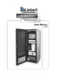
Liebert PEX
Efficiency And Reliability For High Availability Cooling
Technical Data Manual
Contents
Design:
Introduction.......................................................................................................1 - 1
Configuration Nomenclature........................................................................1 - 3
Model Configuration.......................................................................................1 - 15
Features and Benefits .....................................................................................1 - 4
Technical Data (50Hz):
Upflow Air/Water/Glycol Cooled/Dual Cool/Free Cool ......................2 - 1
Downflow Air/Water/Glycol Cooled/Dual Cool/Free Cool.................2 - 13
iCOM Control System: ...............................................................................3 - 1
Guide Specifications: ...................................................................................4 - 1
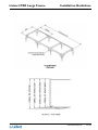
Installation Guidelines: ..............................................................................5 - 1
Unit Dimensions & Service Access..............................................................5 - 4
v. 130710
Technical Data Manual
i
Design
Liebert PEX Large Frame
Introduction
The Liebert PEX is the new generation precision air conditioning system from Emerson Network Power. The
Liebert PEX is the very latest in a long line of advanced products from the Liebert family designed to support
business-critical applications.
Sensitive electronics must be maintained in a stable environment of 20oC to 25oC with a relative humidity of 40%
to 55% . Precision air conditioning systems must not only keep room conditions within this range, they must have
the precision to react quickly to fluctuations in heat load and prevent wide temperature fluctuations.
Liebert PEX units are specifically developed for applications requiring close environmental control:
•
•
•
•
•
•
Data Centres
Telecom/CATV
Computer Rooms
Labs and Test Rooms
Network Centres
Production Facilities
The Liebert PEX Advantage
Only the Liebert PEX can give you all these advantages:
•
Comprehensive local support.
Full pre-sales and post-sales support is readily available, anytime you need it.
•
Customisation expertise.
Liebert PEX units can be customised to suit your requirements, with expertise and assistance from local
Engineering teams.
•
Full Service capability
Factory-trained Customer Service Engineers provide backup support 24 x 365.
•
Established company
Emerson Network Power has been designing and manufacturing precision environmental control systems
for over 45 years.
Technical Data Manual
1-1
Design
Liebert PEX Large Frame
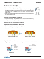
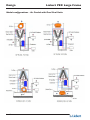
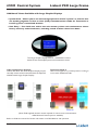
Liebert PEX Large Frame Downflow unit
Downflow models available with
• FC Forward Curve fans
•EC Backward Curve fans with in-floor operation which is the optimum position for energy efficient
performance
• The fans are serviceable and removable from the front of the units above the raised floor whilst the EC fan
models are supplied with a lifting/lowering device for start up & service access
With front (removable) doors open
Liebert PEX Large Frame Upflow unit
Upflow models available with
• FC Forward Curve fans
• EC Backward Curve fans
• The fans are serviceable and removable from the front of the unit.
With front (removable) doors open
1-2
Technical Data Manual
Design
Liebert PEX Large Frame
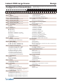
Configuration Nomenclature
1
2
3
4
5
P
2
0
5
0 D A 5
Digit 1
P
Digit 2
2
Digit 3
0-9
Digit 4
0-9
Digit 5
0-9
Digit 6
U
D
Digit 7
A
W
G
D
H
F
C
R
Digit 8
1
S
Digit 9
3
T
A
Digit 10
C
S
E
D
J
F
2
3
Digit 11
0
H
S
Digit 12
S
L
Digit 13
0
1
2
Digit 14
2
3
Digit 15
S
4
K
N
P
6
7
8
9 10
3
11
12
S H L
Model Range
PEX
Modules
Number of Modules/Bays
Cooling Capacity kW
Nominal Gross Cooling Capacity - kW
Cooling Capacity kW
Nominal Gross Cooling Capacity - kW
Cooling Capacity kW
Nominal Gross Cooling Capacity - kW
Air Discharge
Upflow
Downflow
System Type
Air Cooled
Water Cooled
Glycol Cooled
Dual Cool - chilled water + air cooled
Dual Cool - chilled water + water cooled
Free Cool
Chilled Water
Chilled Water Dual Source
Airflow
EC Plug fan - Standard Static
Forward Curved fan - Standard Static
Power Supply
400V / 3ph / 50Hz+N
380V / 3ph / 60Hz - Chilled Water Only
460V / 3ph / 60Hz - Chilled Water Only
Compressor & Refrigerant
Compliant Scroll Single Circuit R407C
Compliant Scroll Dual Circuit R407C
Digital Scroll Single Circuit R407C
Digital Scroll Dual Circuit R407C
Compliant Scroll Single Circuit R22
Compliant Scroll Dual Circuit R22
CW Two way Valves Standard Pressure
CW Three way Valves Standard Pressure
Humidification
None
Infrared Humidifier
Electrode humidifier
Display
Small Display 1 TH Sensor
Large Display 1 TH sensor
Re-Heating
None
Electric heating Std 1 Stage
Electric heating Opt. 2 nd Stage Up
Filtration
G4 (EU4) gravimetric (ref MERV 8) + Clogged Filter
F5 (EU5) dust spot + Clogged Filter
Coil and Valves
Standard Dx Air Cooled Coil
Coil DX -All valves High Pressure MBV, DX - 2 way, CW coil 2 way
Coil DX -All valves High Pressure, MBV, DX - 3 way, CW coil 3 way
Coil DX -All valves High Pressure MBV, DX - 2 way, CW coil 3 way
Coil DX -All valves High Pressure, MBV, DX - 3 way, CW coil 2 way
The basic model can be defined by first 10 digits whilst the unit is fully
defined by 25 digits.
13
14
15
16
17
18
19
20
21
22
23
24
25
1
2
4
1
0
0
0
0
P
0
0
0
0
Digit 16
1
2
6
Digit 17
0
D
Digit 18
0
H
Digit 19
0
1
2
3
4
5
6
D
E
F
G
H
Digit 20
0
S
H
N
F
Digit 21
P
C
Digit 22
A
Z
T
C
Digit 23
0
1
2
3
X
Digit 24
0
L
X
Digit 25
0
X
Enclosure options
Standard Color Charcoal grey
Colour Special color
Color Charcoal grey w/Double skin
Mains Switch High Voltage Option
None
Main non-Locking Disconnect
Lock Out Low Voltage Option
None
Reheat & Humidity Lockout
Monitoring
Monitoring - No Card
Monitoring - IS WEB only
Monitoring - Two ISWEB
Monitoring - IS485 only
Monitoring - Two IS485
Monitoring - ISWEB & IS485
Monitoring - iCOM DO
Monitoring - ISWEB & iCOM DO
Monitoring - Two ISWEB & iCOM DO
Monitoring - IS485 & iCOM DO
Monitoring - Two IS485 & iCOM DO
Monitoring - ISWEB & IS485 & iCOM DO
Sensors
None
Smoke Sensor
High Temperature
Hot and Cold Isle Sensor A & Sensor B (In addition to Standard Sensor)
Smoke & High Temp
Packaging
Packaging - Standard
Packaging - Wooden Crate Export
Special Requirements
SFA - none
For internal use only
For internal use only
For internal use only
Order Identifier
None
High ESP 100 Pa
High ESP 200 Pa
High AirFlow/ESP other
SFA included
Order Identifier
None
Air Cooled - Long Pipe Run Kit > 30 metres
SFA included
Order Identifier
None
SFA included
Technical Data Manual
1-3
Design
Liebert PEX Large Frame
Features and Benefits
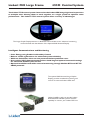
iCOM - Intelligent Communications and Monitoring
The Liebert iCOM™ control system offers the highest capabilities
of unit control, communication and monitoring of Liebert missioncritical cooling units. Liebert iCOM provides advanced diagnostic
and maintenance support, enabling multiple units to communicate
and work together as a team to precisely control temperature
and humidity across a room. In addition, the iCOM network
provides a choice of Teamwork, Lead/Lag and Cascade functions.
Unit to Unit Configuration
Teamwork Mode
A-Frame or V-Frame Evaporator Coils
• High efficiency heat exchanger design features an A-Frame coil for downflow and V-Frame coil for upflow
for precise control of cooling and dehumidification, designed to optimise heat transfer and minimise air side
pressure drop
• Draw-through design pulls air evenly through the large face area cooling coil to maximise heat transfer efficiency
• Double-angle condensate trays ensure correct water drainage.
High Sensible Heat Ratio (SHR)
• All models operate high sensible heat ratios to match the low latent loads of modern computer rooms and
telephone exchanges etc.
• With low latent capacity, little moisture is removed from the air so that humidity levels can be maintained
without extra humidification, thereby ensuring lower energy consumption
High Airflow
• High airflow achieves favourable sensible heat ratios and provides maximum air change rate to ensure variations
in room load are quickly detected and responded to.
1-4
Technical Data Manual
Design
Liebert PEX Large Frame
Features and Benefits
DX Systems - Dehumidification Cycle (FC Fans)
• Compressorised models with forward curve (FC) fans employ split coil configurations,
allowing latent cooling capacity to be substantially increased but only as required so
that energy consumption is minimised whilst providing close temperature and humidity
control. Room loads as low as 35% of unit cooling capacity can be supported with
standard reheat.
• Smaller heater size and unit full load amps (FLA) lowers electrical connection requirements
and reduces installation costs
DX Systems - Dehumidification Cycle (EC Fans)
• Compressorised models with backward curve (EC) fans employ reduced airflow in
conjunction with compressor operation for dehumidification to further minimise energy
consumption whilst providing close temperature and humidity control.
DX Systems - EC Fans and Digital Scroll Compressors
Digital Scroll Capacity Modulation – How it works
•
•
•
•
Takes Advantage Of Copeland Scroll Axial Compliance
When Scrolls Are Separated Axially (~ 1.0 mm), No Gas Flow
When Scrolls Are In Contact, 100% Gas Flow
20-100% Continuous Capacity
1mm
Scroll Separated - No Pump
Scrolls in contact - Pumping
Digital Scroll How it works
• Digital compressor alternates two different working states: the loaded state and the unloaded one
Solenoid
Energized
Solenoid
De-energized
High Discharge
Gas removed,
Moves orbiting
Scroll down
Moves orbiting
Scroll up1.0mm
Unload State
Load State
Technical Data Manual
1-5
Design
•
•
Liebert PEX Large Frame
A solenoid valve the controller approaches and moves away the rotating scroll and the fixed one, using the
axial compliance
Solenoid
An entire cycle lasts 20 seconds (Nominal default setting)
Modular
Chamber
10 Secs 10 Secs
100% Capacity
Bleed Hole
Spring
0% Capacity
Lift Piston
20 Secs
50% Load
Digital Scroll Capacity Modulation examples
Full Capacity
Zero Capacity
4 Sec
5.4
Sec
11 Sec
14.6
Sec
27% of full capacity
10
7.5 Sec
Sec
10
7.5Sec
Sec
50% of full capacity
Application of Digital Scroll in Liebert PEX
• Better room condition control by adapting to the load
• Better temperature control by adapting to latent conditions
• Better humidity control by adapting to RH% (latent) conditions
• Improved reliability by avoiding cycling
• Lower operating costs due to more efficient operation
• Available on Air Cooled, Water Cooled, Glycol Cooled, Dual Cool and Free Cool models
• Both compressors are Digital Scroll type on 2 compressor models
Liebert PEX Digital – Key Benefits
• No Electromagnetic Interference
• Easy Oil Return
• Flexibility
• Immediate adaptation to changing load
• Energy saving solution
• Capability to grow together with your business
• Precise Control
• More precise room temperature control
Modulating Capacity Control from 10 to 75kW
1-6
Technical Data Manual
Liebert PEX Large Frame
Design
Increased Reliability and Compressor life
• Increasing compressor cycling takes a toll on compressor life.
• Liebert Digital Scroll compressors automatically adjust to yearly increase in heat load, providing significantly
greater component life than other compressor technologies.
Liebert PEX – The combination of Digital Scroll Compressor and EC Fans to provide the
Ultimate Energy Machine
•
•
•
•
A combination of 3 energy saving features to provide up to 50% energy savings
Digital Scroll
• Capacity modulation
• Energy saving
• Quick adaptation to changing heat loads
EC Fans
• Variable air flow
• Energy saving
iCOM Control
• ‘Intelligent’ control combines operation of the Digital Compressors and EC fans.
Technical Data Manual
1-7
Design
Liebert PEX Large Frame
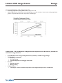
Standard Compressor and EC fan system
• Capacity variation is derived by cycling the compressor ON or OFF to meet the room load e.g. for a room
load of 7kW with a 10kW unit, the compressor would be required to operate 70% of the time say 3.5 minutes
on for 1.5 minutes off.
• However for reliability requirements the compressor normally needs to be on for 3 mins and off for 3 mins.
irrespective of temperature requirements.
• So the saw tooth effect is even more exaggerated
Digital Scroll Compressor
• Cooling Capacity is provided by capacity modulation of the compressor
• Therefore the refrigeration capacity provided by each compressor is 20% to 100% of full capacity
• Capacity variation is derived by capacity modulation of the Digital scroll compressor from a loaded state
to an unloaded state in 20 second band to meet the cooling capacity requirement e.g. for a room load of
7kW with a 10kW unit the Digital Scroll compressor the compressor would be loaded for 14 seconds and
unloaded for 6 seconds
• The cycle time of around 6% of a standard on / off type compressor system
• This provides a precise temperature control showing an almost linear line temperature graph
• Since the digital scroll compressor does not have to cycle on and off to meet the room load it’s reliability
further increased
1-8
Technical Data Manual
Liebert PEX Large Frame
Design
The Ultimate system Digital Scroll Compressor and EC fan technology
• By the combination of the Digital Compressors and EC Fan managed by the iCOM controls the ultimate
control of conditions can be provided by the Liebert PEX unit which has the ability to match the room load
• The capacity modulation compressor / refrigeration capability and the variable air side capacity provided by
the Liebert PEX unit ranges from 20% to 100% of full capacity
• This provides a precise temperature control resulting in an almost linear line temperature graph
• Since the digital scroll compressor does not have to cycle on and off to meet the room load ireliability is
maximised.
• Rivals standard units require
• on/off compressor cycling - decresed reliability
• require more hours of Humidifier operation - energy efficient
• require compressors to run longer at 100% capacity and then require reheat to to maintain room
temperature - inefficient operation
20%
Technical Data Manual
1-9
Design
Liebert PEX Large Frame
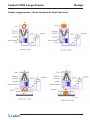
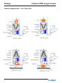
Main Features of Liebert PEX Models
Upflow models available with
• FC Forward Curve fans
• EC Backward Curve fans
• The fans are serviceable and removable from the front of the units
Downflow models available with
• FC Forward Curve fans
• EC Backward Curve fans with in-floor operation which is the optimum position for energy efficient
performance
• The fans are serviceable and removable from the front of the units above the raised floor whilst the EC fan
models are supplied with a lifting/lowering device for start up & service access
EC Fan Transport Mode - Downflow
1 - 10
Technical Data Manual
EC Fan Operation Mode for
maximum efficiency - Downflow
(Requires a minimum of 325mm from raised floor.)
Design
Liebert PEX Large Frame
Features and Benefits
Forward Curve FC Fans
• Forward curve double width double inlet (DWDI) centrifugal fans coupled
to high efficiency motors are standard on all models
• Innovative belt drive system automatically provides high belt tension during
startup eliminating slippage and greatly extending belt life
• Fan belts changed in seconds without tools
• High external static pressure (ESP) motor options available
EC Direct Drive Fan
All models are available with direct drive fans offering:
• High efficiency, external rotor electronically commutated (EC) motor with
integrated electronics
• True soft start characteristics (inrush current lower than operating current)
• Backward curve, corrosion resistant aluminium fan wheel
• Maintenance free design and construction
• High external static pressure (ESP) motor options available
All downflow units with EC fans feature an ‘in-floor’ fan configuration to deliver
the ultimate in energy efficiency. Fans are pre wired and easily lowered into the
floor after unit positioning on site. No extra assembly of components, sections,
fans or wiring etc. required.
Technical Data Manual
1 - 11
Design
Liebert PEX Large Frame
Features and Benefits
Humidifier options
Infrared humidification is standard on all Large Frame PEX models. Steam electrode (cylinder) humidification is
available as an option.
Infrared Humidifier
• Instant humidification - high intensity quartz infrared lamps provide fast, responsive, energy efficient
humidification
• Full capacity achieved in 5-6 seconds therefore no wasted overshoot and energy waste.
• Particle free water vapour introduced into coil bypass air avoids condensation
• Autoflush™ cycle helps remove mineral deposits
• Cleanable stainless steel humidifier pan
• Will operate effectively using almost any water quality.
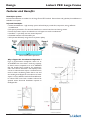
Infrared Humidifier Operation
Why is Bypass Air Introduction Important ?
From a psychrometric standpoint, return air at
24oC/45%RH has more than 5 times the capacity
to absorb steam compared to air at 14oC/80%RH
that has already been cooled by the evaporator
and is now close to saturation. The capacity of this
cool air to absorb water vapour is limited and can
result in water condensing within the air unit and
surrounding areas. Bypass air introduction of water
vapour is a more efficient method of humidification.
In Liebert PEX units both standard infrared &
optional steam electrode humidifiers operate in
the Bypass Air.
1 - 12
Technical Data Manual
Design
Liebert PEX Large Frame
Features and Benefits
Electrode Humidifier (Optional)
• Direct acting electrode design suitable for a wide range of water quality
• Fail safe operation (electrodes will not function without water)
• Water vapour introduced into coil bypass air avoids condensation
• Fully serviceable cylinder bottle ensures quick and cost effective maintenance
Electric Heaters
• Single stage electric reheat system (2nd stage optional) with integral safeties
• 304 stainless steel, low watt density, fin-tubular elements
• Protected by Ground Current Detector
• Standard Reheat/Humidifier lockout - reduces power requirements during emergency power operation
• Heater sub assemblies are replaceable from the front of the unit
Stainess Steel Electric Heaters Assembly
Choice of Refrigerants
All compressorised models are designed to operate on either HFC R407C refrigerants or HCFC R22.
All Digital Compressor models are available with HFC R407C.
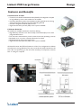
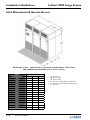
Footprint & Serviceability
• High kW to footprint ratio
• Front accessible for installation and routine servicing
• Front doors are hinged and removeable, offering improved service access to the unit internals
• Compressors, water cooled condensers and filter driers employ rotalock connections for ease of removal i.e.,
no ‘hot’ works
• Front withdrawable air filters allow downflow units to be connected to return air ductwork
Unit Footprint Including
Service Access (m2)
Technical Data Manual
1 - 13
Design
Liebert PEX Large Frame
Filtration
The metal framed filter panels are an integral part of the system and withdrawable from the front of the unit.
Filtration shall be provided by deep V form, dry disposable media housed in a metal frame. The rated efficiency
shall be to G4/EU4/MERV8 Standards.
Metal frame deep V form filter panel
Thermal Expansion Valve
To provide quick and accurate refrigerant system set up and calibration, the thermal expansion valve (TXV) is
accessible via an access hatch to allow system set up and calibration while the unit is running.
1 - 14
Technical Data Manual
Liebert PEX Large Frame
Design
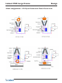
Model configurations - DX Air Cooled with Air Cooled Condenser Units
Technical Data Manual
1 - 15
Design
Liebert PEX Large Frame
Model configurations - DX Water Cooled with Cooling Tower Units
1 - 16
Technical Data Manual
Liebert PEX Large Frame
Design
Model configurations - DX Glycol Cooled with Closed Circuit Units
Technical Data Manual
1 - 17
Design
Liebert PEX Large Frame
Model configurations - Air Cooled with Dual Cool Units
1 - 18
Technical Data Manual
Design
Liebert PEX Large Frame
Model configurations - Water Cooled with Dual Cool Units
Technical Data Manual
1 - 19
Design
Model configurations - Free Cool Units
1 - 20
Technical Data Manual
Liebert PEX Large Frame
Technical Data
Liebert PEX Large Frame
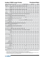
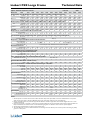
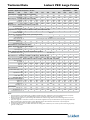
Upflow - DX Scroll compressors + FC fans
Air/Water Cooled
50Hz
Model Size
PEX
1020 1025 1030 1035
Rated Capacity 24°C DB, 50% RH, 45° Condensing
2035
2045
2055
2040
2050
2060
2070
3070
3080
3090
3100
Total kW 19.4
22.1
29.2
32.4
Sensible kW 18.3
20.7
25.9
28.0
Rated Capacity 24°C DB, 45% RH, 45° Condensing
36.5
34.8
44.4
40.7
52.0
46.1
39.5
37.2
45.7
42.0
57.9
51.6
65.9
56.3
71.8
66.2
79.4
69.2
87.2
77.5
97.9
83.9
Total kW 19.3
21.9
28.1
31.8
36.5
42.9
49.7
39.5
44.5
56.4
63.5
70.0
76.7
83.5
96.5
Sensible kW 19.1
21.7
27.4
29.9
36.2
42.6
48.8
39.2
44.2
55.1
59.7
69.5
73.5
82.2
89.9
Air Flow
m3/h 5,400 6,300 7,870 7920 9,720 11,610 13,030 10,440 12,240 15,390 15480 19,190 19,190 22,770 22,860
Evaporator Fan - Forward curve FC centrifugal fan, induction motor, auto-tensioning belt drive
No. of fan assemblies
1
1
1
1
2
2
2
2
Std. Motor - kW
2.2
2.2
3.0
3.0
2.2
2.2
2.2
2.2
Evaporator Coil - Copper tubes with rifled bore tubes, louvred aluminium fins
No. of rows
3
3
3
4
3
3
Fin series - FPM(FPI)
Compressor - Copeland Compliant Scroll with Crankase Heater
No. of compressors
Unit cooling steps
Safety controls - kPa
Humidification Control
1
1
1
3
3
550 (14)
2
2.2
2
3.0
2
3.0
3
2.2
3
2.2
3
3.0
3
3.0
3
4
4
3
3
3
4
2
2
2
1
1
1
1
2
2
2
2
2
2 via HGBP
2 via Compressors
LP cut out/in(auto reset) 140/420, HP cut out (manual reset) 2800
Infrared - kg/h
4.5
4.5
4.5
4.5
10
10
10
Opt. Electrode - kg/h
5
5
5
5
10
10
10
Dehumidification control - Partialised Coil, Split Suction, Solenoid Control
Reheat - Single stage, electric heater elements
10
10
10
10
10
10
10
10
10
10
10
10
10
10
10
10
1 stage - kW
6
6
6
6
9
9
Opt. 2 stage - kW
12
12
12
12
18
18
Filter - Metal Frame, Deep V dry media disposable G4 type filter
9
18
9
18
9
18
9
18
12
24
12
24
12
24
12
24
Nominal W x D x H - mm
800 x 660 x 100
Qty
1
1
1
1
2
2
2
2
2
Full Load Current - 400 Volts, 3 phase+N+E, 50 Hz Supply - Std DX unit only
2
2
3
3
3
3
64.0
65.3
71.1
82.3
92.3
9
18
RFLA 24.0
26.1
33.1
35.0
42.6
48.4
53.4
42.0
46.2
60.2
Water Cooled Condenser - 316SS Brazed Plate Heat Exchanger- 3 Way MBV (Opt. 2 Way MBV)
No. of Condensers
1
No. of MBV
1
Valve Size DN25
Flow - l/s
1.0
PD - kPa
48
Unit Connections
1
1
DN25
1.2
62
1
1
DN25
1.6
77
1
1
DN25
1.7
56
1
1
DN25
1.9
67
1
1
DN25
2.3
81
1
1
DN32
2.8
76
2
2
DN25
2.1
50
2
2
DN25
2.4
63
2
2
DN25
3.2
78
2
2
DN25
3.5
57
2
2
DN25
3.7
63
2
2
DN25
4.2
79
2
2
DN25
4.7
80
2
2
DN32
5.3
69
Hot Gas - O.D.
Qty
Liquid - O.D.
Qty
Condenser Water Supply - I.D.
Qty
Condenser Water Return - O.D.
Qty
Drain - Barb - mm
Hum. Supply - BSP - M
Unit Dimensions & Weight
22
1
16
1
35
1
35
1
19
1/2"
22
1
16
1
35
1
35
1
19
1/2"
22
1
16
1
35
1
35
1
19
1/2"
22
1
16
1
35
1
35
1
19
1/2"
22
1
16
1
35
1
35
1
19
1/2"
22
1
16
1
35
1
35
1
19
1/2"
22
1
16
1
35
1
35
1
19
1/2"
22
2
16
2
35
2
35
2
19
1/2"
22
2
16
2
35
2
35
2
19
1/2"
22
2
16
2
35
2
35
2
19
1/2"
22
2
16
2
35
2
35
2
19
1/2"
22
2
16
2
35
2
35
2
19
1/2"
22
2
16
2
35
2
35
2
19
1/2"
22
2
16
2
35
2
35
2
19
1/2"
22
2
16
2
35
2
35
2
19
1/2"
Width - mm
Depth - mm
Height - mm
Unit Weight - kg
Unit Footprint
853
873
853
873
853
873
853
873
1703
873
1703
873
1703
873
1703
873
1703
873
1703
873
2553
873
2553
873
2553
873
2553
873
350
360
370
380
600
610
630
1703
873
1970
650
670
700
720
970
990
1030
1050
0.74
1.47
0.74
1.47
0.74
1.47
0.74
1.47
1.49
2.93
1.49
2.93
1.49
2.93
1.49
2.93
850
1.49
2.93
1.49
2.93
1.49
2.93
2.23
4.40
2.23
4.40
2.23
4.40
2.23
4.40
Unit only - m 2
Incl. Service area - m2
Service Access min - mm
Notes
1.
2.
3.
4.
All rated capacities are nominal values based on an ESP for Downflow 20pa and for Upflow 50Pa, at sea level for R407C & R22. For net capacities, deduct fan input power. Refer to the Liebert PEX Rating Program for specific input conditions, air flow, and configuration.
Minimum unit depth without front panels and hinges is 841mm. Weights shown are for water cooled DX models only.
Input power supply 400V +/-15%, 50Hz +/- 2. RFLA is for the standard configuration unit only and excludes all heat rejection equipment, Chillers and Pumps etc. RFLA based on standard unit. Refer to Liebert PEX Rating Program & User Manual for electrical data on optional equipment.
All information and Technical Data are subject to change without notice.
Technical Data Manual
2-1
Technical Data
Liebert PEX Large Frame
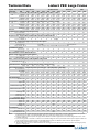
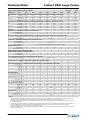
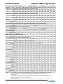
Upflow - DX Scroll compressors + EC fans
Air/Water Cooled
50Hz
Model Size
PEX
1020 1025 1030 1035
Rated Capacity 24°C DB, 50% RH, 45° Condensing
2035
2045
2055
2040
2050
2060
2070
3070
3080
3090
3100
Total kW 19.9
22.4
29.5
32.8
Sensible kW 19.8
22.3
28.0
29.4
Rated Capacity 24°C DB, 45% RH, 45° Condensing
36.6
35.0
44.5
44.2
53.3
52.9
40.7
39.0
45.8
44.6
59.5
57.1
66.3
60.2
71.9
71.4
80.0
77.8
88.0
85.2
98.7
88.9
Total kW 19.8
22.3
29.2
31.4
36.3
44.4
53.1
40.4
45.5
59.1
64.1
71.8
78.9
87.8
94.9
Sensible kW 19.7
22.2
28.9
31.2
36.1
44.2
53.0
40.1
45.0
58.7
63.7
71.5
78.1
87.2
94.2
Air Flow
m3/h 6,500 7,500 8,300 8,500 10,000 14,000 16,000 11,200 13,800 17,000 17,480 23,000 25,000 25,170 25,170
Evaporator Fan - Backward curve EC motor direct drive
No. of fan assemblies
1
1
1
1
2
2
2
2
Std. Motor - kW
2.3
2.3
3.1
3.1
2.3
2.3
2.3
2.3
Evaporator Coil - Copper tubes with rifled bore tubes, louvred aluminium fins
No. of rows
3
3
4
4
3
3
Fin series - FPM(FPI) (max)
Compressor - Copeland Compliant Scroll with Crankase Heater
No. of compressors
Unit cooling steps
Safety controls - kPa
Humidification Control
1
1
1
4
3
550 (14)
2
2.3
2
3.1
2
3.1
3
2.3
3
2.3
3
3.1
3
3.1
3
4
4
3
3
4
4
2
2
2
1
1
1
1
2
2
2
2
2
2 via HGBP
2 via Compressors
LP cut out/in(auto reset) 140/420, HP cut out (manual reset) 2800
Infrared - kg/h
4.5
4.5
4.5
Opt. Electrode - kg/h
5
5
5
Dehumidification control - Reduced air flow
Reheat - Single stage, electric heater elements
4.5
5
10
10
10
10
10
10
10
10
10
10
10
10
10
10
10
10
10
10
10
10
10
10
1 stage - kW
6
6
6
6
9
9
Opt. 2 stage - kW
12
12
12
12
18
18
Filter - Metal Frame, Deep V dry media disposable G4 type filter
9
18
9
18
9
18
9
18
9
18
12
24
12
24
12
24
12
24
Nominal W x D x H - mm
800 x 660 x 100
Qty
1
1
1
1
2
2
2
2
2
Full Load Current - 400 Volts, 3 phase+N+E, 50 Hz Supply - Std DX unit only
2
2
3
3
3
3
60.4
61.4
67.2
76.9
86.9
RFLA 22.7
24.8
31.3
33.2
40.0
45.8
53.4
39.4
43.6
56.6
Water Cooled Condenser - 316SS Brazed Plate Heat Exchanger- 3 Way MBV (Opt. 2 Way MBV)
No. of Condensers
1
No. of MBV
1
Valve Size DN25
Flow - l/s
1.1
PD - kPa
50
Unit Connections
1
1
DN25
1.2
63
1
1
DN25
1.6
77
1
1
DN25
1.8
56
1
1
DN25
1.9
67
1
1
DN25
2.4
83
1
1
DN32
2.8
79
2
2
DN25
2.1
51
2
2
DN25
2.4
64
2
2
DN25
3.2
79
2
2
DN25
3.6
58
2
2
DN25
3.8
65
2
2
DN25
4.3
82
2
2
DN25
4.7
82
2
2
DN32
5.3
71
Hot Gas - O.D.
Qty
Liquid - O.D.
Qty
Condenser Water Supply - I.D.
Qty
Condenser Water Return - O.D.
Qty
Drain - Barb - mm
Hum. Supply - BSP - M
Unit Dimensions & Weight
22
1
16
1
35
1
35
1
19
1/2"
22
1
16
1
35
1
35
1
19
1/2"
22
1
16
1
35
1
35
1
19
1/2"
22
1
16
1
35
1
35
1
19
1/2"
22
1
16
1
35
1
35
1
19
1/2"
22
1
16
1
35
1
35
1
19
1/2"
22
1
16
1
35
1
35
1
19
1/2"
22
2
16
2
35
2
35
2
19
1/2"
22
2
16
2
35
2
35
2
19
1/2"
22
2
16
2
35
2
35
2
19
1/2"
22
2
16
2
35
2
35
2
19
1/2"
22
2
16
2
35
2
35
2
19
1/2"
22
2
16
2
35
2
35
2
19
1/2"
22
2
16
2
35
2
35
2
19
1/2"
22
2
16
2
35
2
35
2
19
1/2"
Width - mm
Depth - mm
Height - mm
Unit Weight - kg
Unit Footprint
853
873
853
873
853
873
853
873
1703
873
1703
873
1703
873
1703
873
1703
873
1703
873
2553
873
2553
873
2553
873
2553
873
350
360
370
380
600
610
630
1703
873
1970
650
670
700
720
970
990
1030
1050
0.74
1.47
0.74
1.47
0.74
1.47
0.74
1.47
1.49
2.93
1.49
2.93
1.49
2.93
1.49
2.93
850
1.49
2.93
1.49
2.93
1.49
2.93
2.23
4.40
2.23
4.40
2.23
4.40
2.23
4.40
Unit only - m 2
Incl. Service area - m2
Service Access min - mm
Notes
1.
2.
3.
4.
5.
2-2
All rated capacities are nominal values based on an ESP for Downflow 20pa and for Upflow 50Pa, at sea level for R407C & R22. For net capacities, deduct fan input power. Refer to the Liebert PEX Rating Program for specific input conditions, air flow, and configuration.
Minimum unit depth without front panels and hinges is 841mm. Minimum raised floor height 325mm for EC fan units. Weights shown are for water
cooled DX models only.
Input power supply 400V +/-15%, 50Hz +/- 2. RFLA is for the standard configuration unit only and excludes all heat rejection equipment, Chillers and
Pumps etc. RFLA based on standard unit. Refer to Liebert PEX Rating Program & User Manual for electrical data on optional equipment.
All information and Technical Data are subject to change without notice.
The Liebert PEX units are now also available with EC Fans. The switching action of the EC Fan power controls may interact with emergency backup
generators or UPS systems.
Technical Data Manual
Technical Data
Liebert PEX Large Frame
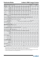
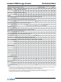
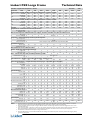
Upflow - DX Digital Scroll Compressors + EC fans
Model Size
PEX
1020
Air/Water Cooled
1025
1030
1035
2035
2040
2050
2060
50Hz
2070
3070
Rated Capacity 24°C DB, 50% RH, 45° Condensing
Total kW
19.9
22.4
26.7
32.8
36.6
40.7
45.8
54.3
66.3
71.9
Sensible kW
19.8
22.3
26.1
29.4
35.0
39.0
44.6
52.7
60.2
71.4
Rated Capacity 24°C DB, 45% RH, 45° Condensing
Total kW
19.8
22.3
26.5
31.4
36.3
40.4
45.5
54.2
64.1
71.8
Sensible kW
19.7
22.2
26.2
31.2
36.1
40.1
45.0
53.8
63.7
71.5
m3/h
6,500
7,500
7,800
8,500
10,000
11,200
13,800
15,500
17,480
23,000
Air Flow
Evaporator Fan - Backward curve EC motor direct drive
No. of fan assemblies
Std. Motor - kW
1
1
1
1
2
2
2
2
2
3
2.3
2.3
3.1
3.1
2.3
2.3
2.3
3.1
3.1
2.3
3
3
4
4
3
2
2
2
2
2
Evaporator Coil - Copper tubes with rifled bore tubes, louvred aluminium fins
No. of rows
3
3
4
4
3
Fin series - FPM(FPI)
550 (14)
Compressor - Copeland Compliant Scroll with Crankase Heater
No. of compressors
1
1
1
1
1
Unit cooling steps
Variable
Safety controls - kPa
LP cut out/in(auto reset) 140/420, HP cut out (manual reset) 2800
Humidification Control
Infrared - kg/h
Opt. Electrode - kg/h
4.5
4.5
4.5
4.5
10
10
10
10
10
10
5
5
5
5
10
10
10
10
10
10
Dehumidification control - Reduced air flow
Reheat - Single stage, electric heater elements
1 stage - kW
6
6
6
6
9
9
9
9
9
12
Opt. 2 stage - kW
12
12
12
12
18
18
18
18
18
24
2
2
2
2
3
40.8
43.6
54.8
60.4
61.4
2
Filter - Metal Frame, Deep V dry media disposable G4 type filter
Nominal W x D x H - mm
Qty
800 x 660 x 100
1
1
1
1
2
Full Load Current - 400 Volts, 3 phase+N+E, 50 Hz Supply - Std DX unit only
RFLA
23.4
24.8
30.4
33.2
40.0
Water Cooled Condenser - 316SS Brazed Plate Heat Exchanger- 3 Way MBV (Opt. 2 Way MBV)
No. of Condensers
1
1
1
1
1
2
2
2
2
No. of MBV
1
1
1
1
1
2
2
2
2
2
Valve Size
DN25
DN25
DN25
DN25
DN25
DN25
DN25
DN25
DN25
DN25
Flow - l/s
1.1
1.2
1.4
1.8
1.9
2.1
2.4
2.9
3.6
3.8
PD - kPa
50
63
65
56
67
51
64
66
58
65
Hot Gas - O.D.
22
22
22
22
22
22
22
22
22
22
Qty
1
1
1
1
1
2
2
2
2
2
Liquid - O.D.
16
16
16
16
16
16
16
16
16
16
Unit Connections
Qty
1
1
1
1
1
2
2
2
2
2
Condenser Water Supply - I.D.
35
35
35
35
35
35
35
35
35
35
Qty
1
1
1
1
1
2
2
2
2
2
Condenser Water Return - O.D.
35
35
35
35
35
35
35
35
35
35
Qty
1
1
1
1
1
2
2
2
2
2
Drain - Barb - mm
19
19
19
19
19
19
19
19
19
19
1/2"
1/2"
1/2"
1/2"
1/2"
1/2"
1/2"
1/2"
1/2"
1/2"
Width - mm
853
853
853
853
1703
1703
1703
1703
1703
2553
Depth - mm
873
873
873
873
873
873
873
873
873
873
Hum. Supply - BSP - M
Unit Dimensions & Weight
Height - mm
Unit Weight - kg
1970
350
360
370
380
600
650
670
700
720
970
Unit only - m2
0.74
0.74
0.74
0.74
1.49
1.49
1.49
1.49
1.49
2.23
Incl. Service area - m2
1.47
1.47
1.47
1.47
2.93
2.93
2.93
2.93
2.93
4.40
Unit Footprint
Service Access min - mm
850
Notes
1.
2.
3.
4.
5.
All rated capacities are nominal values based on an ESP for Downflow 20pa and for Upflow 50Pa, at sea level for R407C & R22. For net capacities, deduct fan input power. Refer to the Liebert PEX Rating Program for specific input conditions, air flow, and configuration.
Minimum unit depth without front panels and hinges is 841mm. Minimum raised floor height 325mm for EC fan units. Weights shown are for water
cooled DX models only.
Input power supply 400V +/-15%, 50Hz +/- 2. RFLA is for the standard configuration unit only and excludes all heat rejection equipment, Chillers and
Pumps etc. RFLA based on standard unit. Refer to Liebert PEX Rating Program & User Manual for electrical data on optional equipment.
All information and Technical Data are subject to change without notice.
The Liebert PEX units are now also available with EC Fans. The switching action of the EC Fan power controls may interact with emergency backup
generators or UPS systems.
Technical Data Manual
2-3
Technical Data
Liebert PEX Large Frame
Upflow - DX Scroll compressors + FC fans
Model Size
PEX
1020
1025
Glycol Cooled
1030
1035
2035
2045
2055
2040
2050
2060
2070
3070
50Hz
3080
3090
3100
Rated Capacity 24°C DB, 50% RH, 54° Condensing
Total kW
17.9
20.9
27.0
30.3
36.6
41.0
48.3
36.7
42.7
54.3
61.8
66.5
73.3
79.8
90.0
Sensible kW
17.8
20.2
25.0
27.1
34.8
39.3
44.6
36.1
40.7
50.1
54.6
64.0
66.7
74.6
80.7
Rated Capacity 24°C DB, 45% RH, 54° Condensing
Total kW
17.9
20.9
26.5
29.2
35.4
41.0
47.0
36.7
42.4
53.3
59.8
66.5
71.3
78.7
87.7
Sensible kW
17.9
20.7
26.3
28.8
35.1
40.6
46.6
36.0
42.1
52.9
58.1
64.1
70.8
78.1
86.2
m3/h
5,400
6,300
7,870
7920
9,720
Air Flow
11,610 13,030 10,440 12,240 15,390 15480 19,190 19,190 22,770 22,860
Evaporator Fan - Forward curve FC centrifugal fan, induction motor, auto-tensioning belt drive
No. of fan assemblies
Std. Motor - kW
1
1
1
1
2
2
2
2
2
2
2
3
3
3
3
2.2
2.2
3.0
3.0
2.2
2.2
2.2
2.2
2.2
3.0
3.0
2.2
2.2
3.0
3.0
3
3
4
4
3
3
3
4
2
2
2
2
2
2
2
Evaporator Coil - Copper tubes with rifled bore tubes, louvred aluminium fins
No. of rows
3
3
3
4
3
3
3
Fin series - FPM(FPI)
550 (14)
Compressor - Copeland Compliant Scroll with Crankase Heater
No. of compressors
1
1
1
Unit cooling steps
1
1
1
1
2
2 via HGBP
Safety controls - kPa
2 via Compressors
LP cut out/in(auto reset) 140/420, HP cut out (manual reset) 2800
Humidification Control
Infrared - kg/h
4.5
4.5
4.5
4.5
10
10
10
Opt. Electrode - kg/h
5
5
5
5
10
10
10
Dehumidification control - Partialised Coil, Split Suction, Solenoid Control
10
10
10
10
10
10
10
10
10
10
10
10
10
10
10
10
Reheat - Single stage, electric heater elements
1 stage - kW
6
6
6
6
9
9
9
9
9
9
9
12
12
12
12
Opt. 2 stage - kW
12
12
12
12
18
18
18
18
18
18
18
24
24
24
24
Filter - Metal Frame, Deep V dry media disposable G4 type filter
Nominal W x D x H - mm
Qty
800 x 660 x 100
1
1
1
1
2
2
2
2
2
2
2
3
3
3
3
42.0
46.2
60.2
64.0
65.3
71.1
82.3
92.3
Full Load Current - 400 Volts, 3 phase+N+E, 50 Hz Supply - Std DX unit only
RFLA 24.0
26.1
33.1
35.0
42.6
48.4
53.4
Water Cooled Condenser - 316SS Brazed Plate Heat Exchanger- 3 Way MBV (Opt. 2 Way MBV)
No. of Condensers
1
1
1
1
1
1
1
2
2
2
2
2
2
2
2
No. of MBV
1
1
1
1
1
1
1
2
2
2
2
2
2
2
2
Valve Size DN25
DN25
DN25
DN25
DN25
DN25
DN32
DN25
DN25
DN25
DN25
DN25
DN25
DN25
DN32
Flow - l/s
1.1
1.3
1.7
1.9
2.0
2.5
2.9
2.2
2.5
3.3
3.7
4.0
4.4
4.9
5.6
PD - kPa
45
59
57
59
68
89
76
47
60
58
60
67
83
88
70
Glycol Supply - I.D..
35
35
35
35
35
35
35
35
35
35
35
35
35
35
35
Qty
1
1
1
1
1
1
1
2
2
2
2
2
2
2
2
Glycol Return - O.D..
35
35
35
35
35
35
35
35
35
35
35
35
35
35
35
Unit Connections
Qty
1
1
1
1
1
1
1
2
2
2
2
2
2
2
2
Drain - Barb - mm
19
19
19
19
19
19
19
19
19
19
19
19
19
19
19
1/2"
1/2"
1/2"
1/2"
1/2"
1/2"
1/2"
1/2"
1/2"
1/2"
1/2"
1/2"
1/2"
1/2"
1/2"
Hum. Supply - BSP - M
Unit Dimensions & Weight
Width - mm
853
853
853
853
1703
1703
1703
1703
1703
1703
1703
2553
2553
2553
2553
Depth - mm
873
873
873
873
873
873
873
873
873
873
873
873
873
873
873
Height - mm
Unit Weight - kg
1970
350
360
370
380
600
610
630
650
670
700
720
970
990
1030
1050
Unit only - m2
0.74
0.74
0.74
0.74
1.49
1.49
1.49
1.49
1.49
1.49
1.49
2.23
2.23
2.23
2.23
Incl. Service area - m2
1.47
1.47
1.47
1.47
2.93
2.93
2.93
2.93
2.93
2.93
2.93
4.40
4.40
4.40
4.40
Unit Footprint
Service Access min - mm
850
Notes
1.
2.
3.
4.
2-4
All rated capacities are nominal values based on an ESP for Downflow 20pa and for Upflow 50Pa, at sea level for R407C & R22. For net capacities, deduct fan input power. Refer to the Liebert PEX Rating Program for specific input conditions, air flow, and configuration.
Minimum unit depth without front panels and hinges is 841mm. Weights shown are for water cooled DX models only.
Input power supply 400V +/-15%, 50Hz +/- 2. RFLA is for the standard configuration unit only and excludes all heat rejection equipment, Chillers and Pumps etc. RFLA based on standard unit. Refer to Liebert PEX Rating Program & User Manual for electrical data on optional equipment.
All information and Technical Data are subject to change without notice.
Technical Data Manual
Technical Data
Liebert PEX Large Frame
Upflow - DX Scroll compressors + EC fans
Model Size
PEX
1020
1025
Glycol Cooled
1030
1035
2035
2045
2055
2040
2050
2060
2070
3070
50Hz
3080
3090
3100
Rated Capacity 24°C DB, 50% RH, 45° Condensing
Total kW
19.2
21.6
27.4
30.4
34.3
42.7
51.2
38.1
43.3
55.7
61.4
69.0
75.2
82.6
90.7
Sensible kW
19.0
21.4
27.1
28.4
34.0
42.4
50.8
37.8
43.0
55.3
58.3
68.5
74.6
82.0
85.7
Rated Capacity 24°C DB, 45% RH, 45° Condensing
Total kW
19.1
21.5
27.3
30.0
34.1
42.5
51.0
38.0
43.2
55.5
61.1
68.7
75.0
82.4
89.8
Sensible kW
19.1
21.5
27.2
29.8
34.0
42.4
50.9
37.9
43.1
55.4
60.6
68.6
74.9
82.2
89.1
m3/h
6,500
7,500
8,300
8,500 10,000 14,000 16,000 11,200 13,800 17,000 17,480 23,000 25,000 25,170 25,170
Air Flow
Evaporator Fan - Backward curve EC motor, direct drive
No. of fan assemblies
Std. Motor - kW
1
1
1
1
2
2
2
2
2
2
2
3
3
3
3
2.3
2.3
3.1
3.1
2.3
2.3
2.3
2.3
2.3
3.1
3.1
2.3
2.3
3.1
3.1
3
3
4
4
3
3
4
4
2
2
2
2
2
2
2
Evaporator Coil - Copper tubes with rifled bore tubes, louvred aluminium fins
No. of rows
3
3
4
4
3
3
4
Fin series - FPM(FPI)
550 (14)
Compressor - Copeland Compliant Scroll with Crankase Heater
No. of compressors
1
1
1
Unit cooling steps
1
1
1
1
2
2 via HGBP
Safety controls - kPa
2 via Compressors
LP cut out/in(auto reset) 140/420, HP cut out (manual reset) 2800
Humidification Control
Infrared - kg/h
4.5
4.5
4.5
Opt. Electrode - kg/h
5
5
5
Dehumidification control - Reduced air flow
4.5
10
10
10
10
10
10
10
10
10
10
10
5
10
10
10
10
10
10
10
10
10
10
10
Reheat - Single stage, electric heater elements
1 stage - kW
6
6
6
6
9
9
9
9
9
9
9
12
12
12
12
Opt. 2 stage - kW
12
12
12
12
18
18
18
18
18
18
18
24
24
24
24
Filter - Metal Frame, Deep V dry media disposable G4 type filter
Nominal W x D x H - mm
Qty
800 x 660 x 100
1
1
1
1
2
2
2
2
2
2
2
3
3
3
3
39.4
43.6
56.6
60.4
61.4
67.2
75.9
86.9
Full Load Current - 400 Volts, 3 phase+N+E, 50 Hz Supply - Std DX unit only
RFLA 22.7
24.8
31.3
33.2
40.0
45.8
53.4
Water Cooled Condenser - 316SS Brazed Plate Heat Exchanger- 3 Way MBV (Opt. 2 Way MBV)
No. of Condensers
1
1
1
1
1
1
1
2
2
2
2
2
2
2
2
No. of MBV
1
1
1
1
1
1
1
2
2
2
2
2
2
2
2
Valve Size DN25
DN25
DN25
DN25
DN25
DN25
DN32
DN25
DN25
DN25
DN25
DN25
DN25
DN25
DN32
Flow - l/s
1.1
1.3
1.7
1.9
2.0
2.5
3.0
2.2
2.6
3.4
3.8
4.1
4.6
4.9
5.6
PD - kPa
48
63
58
59
69
92
81
48
62
59
61
71
87
90
71
Glycol Supply - I.D..
35
35
35
35
35
35
35
35
35
35
35
35
35
35
35
Qty
1
1
1
1
1
1
1
2
2
2
2
2
2
2
2
Glycol Return - O.D..
35
35
35
35
35
35
35
35
35
35
35
35
35
35
35
Unit Connections
Qty
1
1
1
1
1
1
1
2
2
2
2
2
2
2
2
Drain - Barb - mm
19
19
19
19
19
19
19
19
19
19
19
19
19
19
19
1/2"
1/2"
1/2"
1/2"
1/2"
1/2"
1/2"
1/2"
1/2"
1/2"
1/2"
1/2"
1/2"
1/2"
1/2"
Hum. Supply - BSP - M
Unit Dimensions & Weight
Width - mm
853
853
853
853
1703
1703
1703
1703
1703
1703
1703
2553
2553
2553
2553
Depth - mm
873
873
873
873
873
873
873
873
873
873
873
873
873
873
873
Height - mm
Unit Weight - kg
1970
350
360
370
380
600
610
630
650
670
700
720
970
990
1030
1050
Unit only - m2
0.74
0.74
0.74
0.74
1.49
1.49
1.49
1.49
1.49
1.49
1.49
2.23
2.23
2.23
2.23
Incl. Service area - m2
1.47
1.47
1.47
1.47
2.93
2.93
2.93
2.93
2.93
2.93
2.93
4.40
4.40
4.40
4.40
Unit Footprint
Service Access min - mm
850
Notes
1.
2.
3.
4.
5.
All rated capacities are nominal values based on an ESP for Downflow 20pa and for Upflow 50Pa, at sea level for R407C & R22. For net capacities, deduct fan input power. Refer to the Liebert PEX Rating Program for specific input conditions, air flow, and configuration.
Minimum unit depth without front panels and hinges is 841mm. Minimum raised floor height 325mm for EC fan units. Weights shown are for water
cooled DX models only.
Input power supply 400V +/-15%, 50Hz +/- 2. RFLA is for the standard configuration unit only and excludes all heat rejection equipment, Chillers and
Pumps etc. RFLA based on standard unit. Refer to Liebert PEX Rating Program & User Manual for electrical data on optional equipment.
All information and Technical Data are subject to change without notice.
The Liebert PEX units are now also available with EC Fans. The switching action of the EC Fan power controls may interact with emergency backup
generators or UPS systems.
Technical Data Manual
2-5
Technical Data
Liebert PEX Large Frame
Upflow - DX Digital Scroll Compressors + EC fans
Model Size
PEX
1020
1025
1030
1035
2035
2040
2050
Glycol Cooled
50Hz
2060
3070
2070
Rated Capacity 24°C DB, 50% RH, 45˚C Condensing
Total kW
19.2
21.6
25.4
30.4
34.3
38.1
43.3
51.3
61.4
69.0
Sensible kW
19.0
21.4
25.2
28.4
34.0
37.8
43.0
50.9
58.3
68.5
Rated Capacity 24°C DB, 45% RH, 45˚C Condensing
Total kW
19.1
21.5
25.3
30.0
34.1
38.0
43.2
51.1
61.1
68.7
Sensible kW
19.1
21.5
25.2
29.8
34.0
37.9
43.1
51.0
60.6
68.6
m3/h
6,500
7,500
7,800
8,500
10,000
11,200
13,800
15,500
17,480
23,000
Air Flow
Evaporator Fan - Backward curve EC motor, direct drive
No. of fan assemblies
Std. Motor - kW
1
1
1
1
2
2
2
2
2
3
2.3
2.3
3.1
3.1
2.3
2.3
2.3
3.1
3.1
2.3
3
3
4
4
3
2
2
2
2
2
Evaporator Coil - Copper tubes with rifled bore tubes, louvred aluminium fins
No. of rows
3
3
4
4
3
Fin series - FPM(FPI)
550 (14)
Compressor - Copeland Compliant Scroll with Crankase Heater
No. of compressors
1
1
1
1
1
Unit cooling steps
Variable
Safety controls - kPa
LP cut out/in(auto reset) 140/420, HP cut out (manual reset) 2800
Humidification Control
Infrared - kg/h
Opt. Electrode - kg/h
4.5
4.5
4.5
4.5
10
10
10
10
10
10
5
5
5
5
10
10
10
10
10
10
Dehumidification control - Reduced air flow
Reheat - Single stage, electric heater elements
1 stage - kW
6
6
6
6
9
9
9
9
9
12
Opt. 2 stage - kW
12
12
12
12
18
18
18
18
18
24
2
2
2
2
3
40.8
43.6
54.8
60.4
61.4
2
Filter - Metal Frame, Deep V dry media disposable G4 type filter
Nominal W x D x H - mm
Qty
800 x 660 x 100
1
1
1
1
2
Full Load Current - 400 Volts, 3 phase+N+E, 50 Hz Supply - Std DX unit only
RFLA
23.4
24.8
30.4
33.2
40.0
Water Cooled Condenser - 316SS Brazed Plate Heat Exchanger- 3 Way MBV (Opt. 2 Way MBV)
No. of Condensers
1
1
1
1
1
2
2
2
2
No. of MBV
1
1
1
1
1
2
2
2
2
2
Valve Size
DN25
DN25
DN25
DN25
DN25
DN25
DN25
DN25
DN25
DN25
Flow - l/s
1.1
1.3
1.5
1.9
2.0
2.2
2.6
3.0
3.8
4.1
PD - kPa
48
63
49
59
69
48
62
49
61
71
Condenser Water Supply - O.D..
35
35
35
35
35
35
35
35
35
35
Qty
1
1
1
1
1
2
2
2
2
2
Glycol Return - O.D..
35
35
35
35
35
35
35
35
35
35
Unit Connections
Qty
1
1
1
1
1
2
2
2
2
2
Drain - Barb - mm
19
19
19
19
19
19
19
19
19
19
1/2"
1/2"
1/2"
1/2"
1/2"
1/2"
1/2"
1/2"
1/2"
1/2"
Width - mm
853
853
853
853
1703
1703
1703
1703
1703
2553
Depth - mm
873
873
873
873
873
873
873
873
873
873
Hum. Supply - BSP - M
Unit Dimensions & Weight
Height - mm
Unit Weight - kg
1970
350
360
370
380
600
650
670
700
720
970
Unit only - m2
0.74
0.74
0.74
0.74
1.49
1.49
1.49
1.49
1.49
2.23
Incl. Service area - m2
1.47
1.47
1.47
1.47
2.93
2.93
2.93
2.93
2.93
4.40
Unit Footprint
Service Access min - mm
850
Notes
1.
2.
3.
4.
5.
2-6
All rated capacities are nominal values based on an ESP for Downflow 20pa and for Upflow 50Pa, at sea level for R407C & R22. For net capacities, deduct fan input power. Refer to the Liebert PEX Rating Program for specific input conditions, air flow, and configuration.
Minimum unit depth without front panels and hinges is 841mm. Minimum raised floor height 325mm for EC fan units. Weights shown are for water
cooled DX models only.
Input power supply 400V +/-15%, 50Hz +/- 2. RFLA is for the standard configuration unit only and excludes all heat rejection equipment, Chillers and
Pumps etc. RFLA based on standard unit. Refer to Liebert PEX Rating Program & User Manual for electrical data on optional equipment.
All information and Technical Data are subject to change without notice.
The Liebert PEX units are now also available with EC Fans. The switching action of the EC Fan power controls may interact with emergency backup
generators or UPS systems.
Technical Data Manual
Technical Data
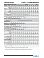
Liebert PEX Large Frame
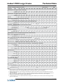
Upflow - DX Scroll compressors + FC fans
Air/Water Cooled
Model Size
PEX
1020
1025
1030
2035
2045
2055
2040
Rated Capacity 24°C DB, 50% RH, 45° Condensing, CW Based on 7˚C EWT, 12˚C LWT
DX
Total kW
19.4
22.1
29.2
36.5
44.4
52.0
39.5
Sensible kW
18.3
20.7
25.9
34.8
40.7
46.1
37.2
CW
Total kW
23.2
25.3
28.5
47.5
53.4
57.3
50.0
Sensible kW
19.5
21.7
25.4
38.0
43.4
47.2
40.1
Rated Capacity 24°C DB, 45% RH, 45° Condensing, CW Based on 7˚C EWT, 12˚C LWT
Dual Cool
2050
2060
3070
3080
3090
45.7
42.0
54.9
45.1
57.9
51.6
62.7
53.0
71.8
66.2
83.6
69.5
79.4
69.2
83.6
69.5
87.2
77.5
91.9
78.5
56.4
55.1
55.7
54.1
15,390
70.0
69.5
73.5
70.8
19,190
76.7
73.5
73.5
70.8
19,190
83.5
82.2
81.4
80.2
22,770
DX
Total kW
19.3
21.9
28.1
36.5
42.9
49.7
39.5
44.5
Sensible kW
19.1
21.7
27.4
36.2
42.6
48.8
39.2
44.2
CW
Total kW
20.5
22.2
25.8
42.2
47.0
50.4
44.2
48.7
Sensible kW
19.9
22.2
25.8
38.6
44.1
48.0
40.8
45.9
Air Flow
m3/h
5,400
6,300
7,870
9,720
11,610
13,030
10,440
12,240
Evaporator Fan - Forward curve FC centrifugal fan, induction motor, auto-tensioning belt drive
No. of fan assemblies
1
1
1
2
2
2
Std. Motor - kW
2.2
2.2
3.0
2.2
2.2
2.2
Evaporator Coil - Copper tubes with rifled bore tubes, louvred aluminium fins
No. of rows
6
6
6
6
Fin series - FPM(FPI)
Compressor - Copeland Compliant Scroll with Crankase Heater
6
No. of compressors
Unit cooling steps
Safety controls - kPa
Humidification Control
1
1
1
1
1
50Hz
2
2.2
2
2.2
2
3.0
3
2.2
3
2.2
3
3.0
6
6
6
6
6
6
2
2
2
6
550 (14)
1
2
2
2
2 via HGBP
LP cut out/in(auto reset) 140/420, HP cut out (manual reset) 2800
Infrared - kg/h
4.5
4.5
4.5
10
10
10
Opt. Electrode - kg/h
5
5
5
10
10
10
Dehumidification control- Standard HVAC dehumidification methology utilised
Reheat - Single stage, electric heater elements
10
10
10
10
10
10
10
10
10
10
10
10
1 stage - kW
6
6
6
9
9
Opt. 2 stage - kW
12
12
12
18
18
Filter - Metal Frame, Deep V dry media disposable G4 type filter
9
18
9
18
9
18
9
18
12
24
12
24
12
24
Nominal W x D x H - mm
Qty
1
1
1
2
2
2
Full Load Current - 400 Volts, 3 phase+N+E, 50 Hz Supply - Std DX unit only
2
2
2
3
3
3
60.2
65.3
71.1
82.3
RFLA 24.0
26.1
33.1
42.6
48.4
53.4
42.0
46.2
Water Cooled Condenser - 316SS Brazed Plate Heat Exchanger- 3 Way MBV (Opt. 2 Way MBV)
No. of Condensers
No. of MBV
Valve Size
Flow - l/s
PD - kPa
Unit Connections
1
1
DN25
1.0
48
1
1
DN25
1.2
62
1
1
DN25
1.5
72
1
1
DN25
1.9
67
1
1
DN25
2.3
81
1
1
DN32
2.7
71
2
2
DN25
2.1
50
2
2
DN25
2.4
63
2
2
DN25
3.0
72
2
2
DN25
3.7
63
2
2
DN25
4.2
79
2
2
DN25
4.5
75
Hot Gas - O.D.
Qty
Liquid - O.D.
Qty
Condenser Water Supply - I.D.
Qty
Condenser Water Return - O.D.
Qty
CW Supply - I.D.
CW Return - O.D.
Drain - Barb - mm
Hum. Supply - BSP - M
Unit Dimensions & Weight
22
1
16
1
35
1
35
1
25
25
19
1/2"
22
1
16
1
35
1
35
1
25
25
19
1/2"
22
1
16
1
35
1
35
1
25
25
19
1/2"
22
1
16
1
35
1
35
1
35
35
19
1/2"
22
1
16
1
35
1
35
1
35
35
19
1/2"
22
1
16
1
35
1
35
1
35
35
19
1/2"
22
2
16
2
35
2
35
2
35
35
19
1/2"
22
2
16
2
35
2
35
2
35
35
19
1/2"
22
2
16
2
35
2
35
2
35
35
19
1/2"
22
2
16
2
42
2
42
2
42
42
19
1/2"
22
2
16
2
42
2
42
2
42
42
19
1/2"
22
2
16
2
42
2
42
2
42
42
19
1/2"
Width - mm
Depth - mm
Height - mm
Unit Weight - kg
Unit Footprint
853
873
853
873
853
873
1703
873
1703
873
1703
873
1703
873
1703
873
1703
873
2553
873
2553
873
2553
873
350
360
370
600
610
630
650
670
700
970
990
1030
Unit only - m2
0.74
1.47
0.74
1.47
0.74
1.47
1.49
2.93
1.49
2.93
1.49
2.93
1.49
2.93
1.49
2.93
1.49
2.93
2.23
4.40
2.23
4.40
2.23
4.40
Incl. Service area - m2
Service Access min - mm
1970
850
Notes
1.
2.
3.
4.
All rated capacities are nominal values based on an ESP for Downflow 20pa and for Upflow 50Pa, at sea level for R407C & R22. For net capacities, deduct fan input power. Refer to the Liebert PEX Rating Program for specific input conditions, air flow, and configuration.
Minimum unit depth without front panels and hinges is 841mm. Weights shown are for water cooled DX models only.
Input power supply 400V +/-15%, 50Hz +/- 2. RFLA is for the standard configuration unit only and excludes all heat rejection equipment, Chillers and Pumps etc. RFLA based on standard unit. Refer to Liebert PEX Rating Program & User Manual for electrical data on optional equipment.
All information and Technical Data are subject to change without notice.
Technical Data Manual
2-7
Technical Data
Liebert PEX Large Frame
Upflow - DX Scroll compressors + EC fans
Air/WateCooled
Dual Cool
Model Size
PEX
1020
1025
1030
2035
2045
2055
2040
Rated Capacity 24°C DB, 50% RH, 45° Condensing, CW Based on 7˚C EWT, 12˚C LWT
2060
3070
3080
3090
45.8
44.6
59.0
49.1
59.3
54.9
66.1
56.7
71.9
71.4
92.6
79.0
80.0
77.8
97.2
83.8
87.5
81.9
97.8
84.2
40.4
40.1
46.0
42.9
11,200
45.5
45.0
52.4
50.1
13,800
58.0
57.6
58.6
58.1
17,000
71.8
71.5
81.3
80.7
23,000
78.9
78.1
85.7
85.7
25,000
86.1
85.4
85.9
85.9
25,170
2
2.3
2
2.3
2
3.1
3
2.3
3
2.3
3
3.1
6
6
6
6
6
6
2
2
DX
Total kW
19.9
22.4
29.3
36.6
44.5
52.2
40.7
Sensible kW
19.8
22.3
26.6
35.0
44.2
50.5
39.0
CW
Total kW
25.7
28.0
29.4
48.6
59.7
63.5
52.2
Sensible kW
22.2
24.6
26.3
38.9
49.6
54.4
42.2
Rated Capacity 24°C DB, 45% RH, 45° Condensing, CW Based on 7˚C EWT, 12˚C LWT
DX
Total kW
19.8
22.3
28.3
Sensible kW
19.7
22.2
28.1
CW
Total kW
22.7
25.0
26.8
Sensible kW
22.7
25.0
26.8
Air Flow
m 3/h
6,500
7,500
8,300
Evaporator Fan - Backward curve EC motor drive
36.3
36.1
42.9
39.5
10,000
44.4
44.2
52.5
50.6
14,000
49.9
49.8
56.3
55.6
16,000
No. of fan assemblies
1
1
1
2
2
2
Std. Motor - kW
2.3
2.3
3.1
2.3
2.3
2.3
Evaporator Coil - Copper tubes with rifled bore tubes, louvred aluminium fins
No. of rows
6
6
6
6
Fin series - FPM(FPI)
Compressor - Copeland Compliant Scroll with Crankase Heater
No. of compressors
Unit cooling steps
Safety controls - kPa
Humidification Control
1
1
6
50Hz
2050
6
550 (14)
1
1
1
1
2
2
2
2
2 via HGBP
2 via Compressors
LP cut out/in(auto reset) 140/420, HP cut out (manual reset) 2800
Infrared - kg/h
4.5
4.5
4.5
Opt. Electrode - kg/h
5
5
5
Dehumidification control - Reduced air flow
Reheat - Single stage, electric heater elements
10
10
10
10
10
10
10
10
10
10
10
10
10
10
10
10
10
10
1 stage - kW
6
6
6
9
9
Opt. 2 stage - kW
12
12
12
18
18
Filter - Metal Frame, Deep V dry media disposable G4 type filter
9
18
9
18
9
18
9
18
12
24
12
24
12
24
Nominal W x D x H - mm
Qty
1
1
1
2
2
2
Full Load Current - 400 Volts, 3 phase+N+E, 50 Hz Supply - Std DX unit only
2
2
2
3
3
3
56.6
61.4
67.2
76.9
RFLA 22.7
24.8
31.3
40.0
45.8
53.4
39.4
43.6
Water Cooled Condenser - 316SS Brazed Plate Heat Exchanger- 3 Way MBV (Opt. 2 Way MBV)
No. of Condensers
No. of MBV
Valve Size
Flow - l/s
PD - kPa
Unit Connections
1
1
DN25
1.1
50
1
1
DN25
1.2
63
1
1
DN25
1.5
72
1
1
DN25
1.9
67
1
1
DN25
2.4
83
1
1
DN32
2.7
73
2
2
DN25
2.1
51
2
2
DN25
2.4
64
2
2
DN25
3.0
73
2
2
DN25
3.8
65
2
2
DN25
4.3
82
2
2
DN25
4.5
76
Hot Gas - O.D.
Qty
Liquid - O.D.
Qty
Condenser Water Supply - I.D.
Qty
Condenser Water Return - O.D.
Qty
CW Supply - I.D.
CW Return - O.D.
Drain - Barb - mm
Hum. Supply - BSP - M
Unit Dimensions & Weight
22
1
16
1
35
1
35
1
25
25
19
1/2"
22
1
16
1
35
1
35
1
25
25
19
1/2"
22
1
16
1
35
1
35
1
25
25
19
1/2"
22
1
16
1
35
1
35
1
35
35
19
1/2"
22
1
16
1
35
1
35
1
35
35
19
1/2"
22
1
16
1
35
1
35
1
35
35
19
1/2"
22
2
16
2
35
2
35
2
35
35
19
1/2"
22
2
16
2
35
2
35
2
35
35
19
1/2"
22
2
16
2
35
2
35
2
35
35
19
1/2"
22
2
16
2
42
2
42
2
42
42
19
1/2"
22
2
16
2
42
2
42
2
42
42
19
1/2"
22
2
16
2
42
2
42
2
42
42
19
1/2"
Width - mm
Depth - mm
Height - mm
Unit Weight - kg
Unit Footprint
853
873
853
873
853
873
1703
873
1703
873
1703
873
1703
873
1703
873
2553
873
2553
873
2553
873
350
360
370
600
610
1703
873
1970
630
650
670
700
970
990
1030
0.74
1.47
0.74
1.47
0.74
1.47
1.49
2.93
1.49
2.93
1.49
2.93
850
1.49
2.93
1.49
2.93
1.49
2.93
2.23
4.40
2.23
4.40
2.23
4.40
Unit only - m 2
Incl. Service area - m2
Service Access min - mm
Notes
2-8
1.
2.
3.
4.
5.
All rated capacities are nominal values based on an ESP for Downflow 20pa and for Upflow 50Pa, at sea level for R407C & R22. For net capacities, deduct fan input power. Refer to the Liebert PEX Rating Program for specific input conditions, air flow, and configuration.
Minimum unit depth without front panels and hinges is 841mm. Minimum raised floor height 325mm for EC fan units. Weights shown are for water
cooled DX models only.
Input power supply 400V +/-15%, 50Hz +/- 2. RFLA is for the standard configuration unit only and excludes all heat rejection equipment, Chillers and
Pumps etc. RFLA based on standard unit. Refer to Liebert PEX Rating Program & User Manual for electrical data on optional equipment.
All information and Technical Data are subject to change without notice.
The Liebert PEX units are now also available with EC Fans. The switching action of the EC Fan power controls may interact with emergency backup
generators or UPS systems.
Technical Data Manual
Technical Data
Liebert PEX Large Frame
Upflow - Digital Scroll Compressors + EC fans
Dual Cool
Model Size
PEX
1020
1025
1030
2035
2040
Rated Capacity 24°C DB, 50% RH, 45˚ Condensing, CW Based on 7˚C EWT, 12˚C LWT
DX
Total kW
19.9
22.4
26.5
36.6
40.7
Sensible kW
19.8
22.3
24.9
35.0
39.0
CW
Total kW
25.7
28.0
28.7
48.6
52.2
Sensible kW
22.2
24.6
25.3
38.9
42.2
Rated Capacity 24°C DB, 45% RH, 45˚ Condensing, CW Based on 7˚C EWT, 12˚C LWT
DX
Total kW
19.8
22.3
Sensible kW
19.7
22.2
CW
Total kW
22.7
25.0
Sensible kW
22.7
25.0
Air Flow
m3/h
6,500
7,500
Evaporator Fan - Backward curve EC motor, direct drive
26.1
25.9
25.8
25.8
7,800
36.3
36.1
42.9
39.5
10,000
40.4
40.1
46.0
42.9
11,200
2050
2060
3070
45.8
44.6
59.0
49.1
54.2
50.4
63.1
53.3
71.9
71.4
92.6
79.0
45.5
45.0
52.4
50.1
13,800
53.1
52.7
55.5
54.4
15,500
71.8
71.5
81.3
80.7
23,000
1
2.3
3
2.3
6
6
2
2
No. of fan assemblies
1
1
1
1
1
1
Std. Motor - kW
2.3
2.3
2.3
2.3
2.3
2.3
Dual Cool DX Evaporator & Chilled Water Coil - Copper tubes with rifled bore tubes, louvred aluminium fins
No. of rows
6
6
6
Fin series - FPM(FPI)
Compressor - Copeland Compliant Scroll with Crankase Heater
6
No. of compressors
Unit cooling steps
Safety controls - kPa
Humidification Control
1
1
4.5
5
10
10
10
10
10
10
10
10
10
10
9
18
9
18
9
18
9
18
12
24
Nominal W x D x H - mm
800 x 660 x 100
Qty
1
1
1
2
2
Full Load Current - 400 Volts, 3 phase+N+E, 50 Hz Supply - Std DX unit only
2
2
3
54.8
61.4
1
1
Infrared - kg/h
4.5
4.5
Opt. Electrode - kg/h
5
5
Dehumidification control - Reduced air flow
Reheat - Single stage, electric heater elements
6
50Hz
6
550 (14)
2
2
Variable
LP cut out/in(auto reset) 140/420, HP cut out (manual reset) 2800
1 stage - kW
6
6
6
Opt. 2 stage - kW
12
12
12
Filter - Metal Frame, Deep V dry media disposable G4 type filter
RFLA
23.4
24.8
30.4
40.0
40.8
43.6
Water Cooled Condenser - 316SS Brazed Plate Heat Exchanger- 3 Way MBV (Opt. 2 Way MBV)
No. of Condensers
No. of MBV
Valve Size
Flow - l/s
PD - kPa
Unit Connections
1
1
DN25
1.1
50
1
1
DN25
1.2
63
1
1
DN25
1.4
60
1
1
DN25
1.9
67
1
1
DN25
2.1
51
1
1
DN32
2.4
64
2
2
DN25
2.8
61
2
2
DN25
3.8
65
Hot Gas - O.D.
Qty
Liquid - O.D.
Qty
Condenser Water Supply - I.D.
Qty
Condenser Water Return - O.D.
Qty
CW Supply - I.D.
CW Return - O.D.
Drain - Barb - mm
Hum. Supply - BSP - M
Unit Dimensions & Weight
22
1
16
1
35
1
35
1
25
25
19
1/2"
22
1
16
1
35
1
35
1
25
25
19
1/2"
22
1
16
1
35
1
35
1
25
25
19
1/2"
22
1
16
1
35
1
35
1
35
35
19
1/2"
22
2
16
2
35
2
35
2
35
35
19
1/2"
22
2
16
2
35
2
35
2
35
35
19
1/2"
22
2
16
2
35
2
35
2
35
35
19
1/2"
22
2
16
2
35
3
35
3
35
35
19
1/2"
Width - mm
Depth - mm
Height - mm
Unit Weight - kg
Unit Footprint
853
873
853
873
853
873
1703
873
1703
873
1703
873
1703
873
2553
873
350
360
370
600
650
670
700
970
1970
Unit only - m2
0.74
0.74
0.74
1.49
1.49
1.49
1.49
2.23
Incl. Service area - m2
1.47
1.47
1.47
2.93
2.93
2.93
2.93
4.40
Service Access min - mm
850
1. All rated capacities are nominal values based on an ESP for Downflow 20pa and for Upflow 50Pa, at sea level for R407C & R22. For net capacities, Notes
deduct fan input power. Refer to the Liebert PEX Rating Program for specific input conditions, air flow, and configuration.
2. Minimum unit depth without front panels and hinges is 841mm. Minimum raised floor height 325mm for EC fan units. Weights shown are for water
cooled DX models only.
3. Input power supply 400V +/-15%, 50Hz +/- 2. RFLA is for the standard configuration unit only and excludes all heat rejection equipment, Chillers and
Pumps etc. RFLA based on standard unit. Refer to Liebert PEX Rating Program & User Manual for electrical data on optional equipment.
4. All information and Technical Data are subject to change without notice.
5. The Liebert PEX units are now also available with EC Fans. The switching action of the EC Fan power controls may interact with emergency backup
generators or UPS systems.
Technical Data Manual
2-9
Technical Data
Liebert PEX Large Frame
Upflow - DX Scroll compressors + FC fans
Free Cool
Model Size
PEX
1020
1025
1030
2035
2045
2055
2040
2050
2060
Rated Capacity 24°C DB, 50% RH, 54˚ Condensing, CW Based on 7˚C EWT, 12˚C LWT, and Glycol 30%
DX
Total kW
17.9
20.9
27.0
36.6
41.0
48.3
36.7
42.7
54.3
Sensible kW
17.8
20.2
25.0
34.8
39.3
44.6
36.1
40.7
50.1
Free Cool
Total kW
21.2
23.2
26.1
43.5
48.9
52.4
45.8
50.2
57.4
Sensible kW
18.4
20.6
24.0
36.0
41.0
44.6
37.9
42.6
50.1
Rated Capacity 24°C DB, 45% RH, 54˚C Condensing, CW Based on 7˚C EWT, 12˚C LWT, and Glycol 30%
DX
Total kW
17.9
20.9
26.5
35.4
41.0
47.0
36.7
42.4
Sensible kW
17.9
20.7
26.3
35.1
40.6
46.6
36.0
42.1
Free Cool
Total kW
18.8
20.3
23.6
38.6
43.1
46.2
40.4
44.6
Sensible kW
18.2
20.3
23.6
35.3
40.4
44.0
37.3
42.0
Air Flow
m3/h
5,400
6,300
7,870
9,720
11,610
13,030
10,440
12,240
Evaporator Fan - Forward curve FC centrifugal fan, induction motor, auto-tensioning belt drive
53.3
52.9
51.0
49.6
15,390
50Hz
3070
3080
3090
66.5
64.0
76.5
65.7
73.3
66.7
76.5
65.7
76.8
72.6
84.1
74.2
66.5
64.1
67.3
64.9
19,190
71.3
70.8
67.3
64.9
19,190
75.7
75.1
74.5
73.4
22,770
3
2.2
3
3.0
6
6
2
2
No. of fan assemblies
1
1
1
2
2
2
2
2
2
3
Std. Motor - kW
2.2
2.2
3.0
2.2
2.2
2.2
2.2
2.2
3.0
2.2
Free Cool DX Evaporator & Chilled Water Coil - Copper tubes with rifled bore tubes, louvred aluminium fins
No. of rows
6
6
6
6
Fin series - FPM(FPI)
Compressor - Copeland Compliant Scroll with Crankase Heater
No. of compressors
Unit cooling steps
Safety controls - kPa
Humidification Control
1
1
6
6
6
6
6
6
550 (14)
1
1
1
1
2
2
2
2
2 via HGBP
2 via Compressors
LP cut out/in(auto reset) 140/420, HP cut out (manual reset) 2800
Infrared - kg/h
4.5
4.5
4.5
Opt. Electrode - kg/h
5
5
5
Dehumidification control - N/A
Reheat - Single stage, electric heater elements
10
10
10
10
10
10
10
10
10
10
10
10
10
10
10
10
1 stage - kW
6
6
6
9
9
Opt. 2 stage - kW
12
12
12
18
18
Filter - Metal Frame, Deep V dry media disposable G4 type filter
9
18
9
18
9
18
9
18
12
24
12
24
12
24
2
2
3
3
3
60.2
65.3
71.1
82.3
Nominal W x D x H - mm
Qty
1
1
1
Electrical 400V 50Hz 3Phase - Std DX unit only
10
10
2
2
800 x 660 x 100
2
2
RFLA
24.0
26.1
33.3
42.6
48.4
53.4
42.0
46.2
Water Cooled Condenser - 316SS Brazed Plate Heat Exchanger- 3 Way MBV (Opt. 2 Way MBV)
No. of Condensers
No. of MBV
Valve Size
Flow - l/s
PD - kPa
Unit Connections
1
1
DN25
1.1
45
1
1
DN25
1.3
59
1
1
DN25
1.6
54
1
1
DN25
2.0
68
1
1
DN25
2.5
89
1
1
DN32
2.8
72
2
2
DN25
2.2
47
2
2
DN25
2.5
60
2
2
DN25
3.2
54
2
2
DN25
4.0
67
2
2
DN25
4.4
83
2
2
DN25
4.7
82
Glycol Supply - I.D.
Qty
Glycol Return - O.D.
Qty
Drain - Barb - mm
Hum. Supply - BSP - M
Unit Dimensions & Weight
35
1
35
1
19
1/2"
35
1
35
1
19
1/2"
35
1
35
1
19
1/2"
35
1
35
1
19
1/2"
35
1
35
1
19
1/2"
35
1
35
1
19
1/2"
35
2
35
2
19
1/2"
35
2
35
2
19
1/2"
35
2
35
2
19
1/2"
42
2
42
2
19
1/2"
42
2
42
2
19
1/2"
42
2
42
2
19
1/2"
Width - mm
Depth - mm
Height - mm
Unit Weight - kg
Unit Footprint
853
873
853
873
853
873
1703
873
1703
873
1703
873
1703
873
1703
873
2553
873
2553
873
2553
873
350
360
370
600
610
1703
873
1970
630
650
670
700
970
990
1030
Unit only - m2
Incl. Service area - m2
Service Access min - mm
0.74
1.47
0.74
1.47
0.74
1.47
1.49
2.93
1.49
2.93
1.49
2.93
850
1.49
2.93
1.49
2.93
1.49
2.93
2.23
4.40
2.23
4.40
2.23
4.40
Notes
1.
2.
3.
4.
All rated capacities are nominal values based on an ESP for Downflow 20pa and for Upflow 50Pa, at sea level for R407C & R22. For net capacities, deduct fan input power. Refer to the Liebert PEX Rating Program for specific input conditions, air flow, and configuration.
Minimum unit depth without front panels and hinges is 841mm. Weights shown are for water cooled DX models only.
Input power supply 400V +/-15%, 50Hz +/- 2. RFLA is for the standard configuration unit only and excludes all heat rejection equipment, Chillers and Pumps etc. RFLA based on standard unit. Refer to Liebert PEX Rating Program & User Manual for electrical data on optional equipment.
All information and Technical Data are subject to change without notice
2-10
Technical Data Manual
Technical Data
Liebert PEX Large Frame
Upflow - DX Scroll compressors + EC fans
Free Cool
Model Size
PEX
1020
1025
1030
2035
2045
2055
2040
2050
2060
Rated Capacity 24°C DB, 50% RH, 54˚ Condensing, CW Based on 7˚C EWT, 12˚C LWT, and Glycol 30%
DX
Total kW
19.2
21.6
27.1
34.3
42.7
48.8
38.1
43.3
54.9
Sensible kW
19.0
21.4
25.8
34.0
42.4
48.5
37.8
43.0
53.2
Free Cool
Total kW
23.5
25.7
27.0
44.5
54.6
58.2
47.8
54.0
60.5
Sensible kW
21.0
23.2
24.9
36.8
46.9
51.4
39.9
46.4
53.6
Rated Capacity 24°C DB, 45% RH, 54˚C Condensing, CW Based on 7˚C EWT, 12˚C LWT, and Glycol 30%
DX
Total kW
19.1
21.5
27.0
34.1
Sensible kW
19.1
21.5
26.8
34.0
Free Cool
Total kW
20.8
22.9
24.5
39.3
Sensible kW
20.8
22.9
24.5
36.1
Air Flow
m3/h
6,500
7,500
8,300
10,000
Evaporator Fan - Backward Curve EC motor, direct drive
42.5
42.4
48.1
46.3
14,000
48.6
48.4
51.6
50.9
16,000
38.0
37.9
42.1
39.3
11,200
43.2
43.1
48.0
45.8
13,800
52.1
52.0
53.7
53.2
17,000
50Hz
3070
3080
3090
69.0
68.5
84.8
74.7
75.2
74.6
89.0
79.2
81.0
78.5
89.5
79.6
68.7
68.6
74.4
73.9
23,000
75.0
74.9
78.4
78.4
25,000
80.8
80.0
78.7
78.7
25,170
3
2.3
3
3.1
6
6
2
2
No. of fan assemblies
1
1
1
2
2
2
2
2
2
3
Std. Motor - kW
2.3
2.3
3.1
2.3
2.3
2.3
2.3
2.3
3.1
2.3
Free Cool DX Evaporator & Chilled Water Coil - Copper tubes with rifled bore tubes, louvred aluminium fins
No. of rows
6
6
6
6
Fin series - FPM(FPI)
Compressor - Copeland Compliant Scroll with Crankase Heater
No. of compressors
Unit cooling steps
Safety controls - kPa
Humidification Control
1
1
6
6
6
6
6
6
550 (14)
1
1
1
1
2
2
2
2
2 via HGBP
2 via Compressors
LP cut out/in(auto reset) 140/420, HP cut out (manual reset) 2800
Infrared - kg/h
4.5
4.5
4.5
Opt. Electrode - kg/h
5
5
5
Dehumidification control - Variable EC fan speed
Reheat - Single stage, electric heater elements
10
10
10
10
10
10
10
10
10
10
10
10
10
10
10
10
1 stage - kW
6
6
6
9
9
Opt. 2 stage - kW
12
12
12
18
18
Filter - Metal Frame, Deep V dry media disposable G4 type filter
9
18
9
18
9
18
9
18
12
24
12
24
12
24
2
2
3
3
3
39.4
43.6
56.6
61.4
67.2
76.9
Nominal W x D x H - mm
Qty
1
1
1
Electrical 400V 50Hz 3Phase - Std DX unit only
10
10
2
2
800 x 660 x 100
2
2
RFLA
22.7
24.8
31.3
40.0
45.8
53.4
Water Cooled Condenser - 316SS Brazed Plate Heat Exchanger- 3 Way MBV
No. of Condensers
No. of MBV
Valve Size
Flow - l/s
PD - kPa
Unit Connections
1
1
DN25
1.1
48
1
1
DN25
1.3
63
1
1
DN25
1.6
54
1
1
DN25
2.0
69
1
1
DN25
2.5
92
1
1
DN32
2.9
75
2
2
DN25
2.2
48
2
2
DN25
2.6
62
2
2
DN25
3.2
55
2
2
DN25
4.1
71
2
2
DN25
4.6
87
2
2
DN25
4.8
83
Glycol Supply - I.D.
Qty
Glycol Return - O.D.
Qty
Drain - Barb - mm
Hum. Supply - BSP - M
Unit Dimensions & Weight
35
1
35
1
19
1/2"
35
1
35
1
19
1/2"
35
1
35
1
19
1/2"
35
1
35
1
19
1/2"
35
1
35
1
19
1/2"
35
1
35
1
19
1/2"
35
2
35
2
19
1/2"
35
2
35
2
19
1/2"
35
2
35
2
19
1/2"
42
2
42
2
19
1/2"
42
2
42
2
19
1/2"
42
2
42
2
19
1/2"
Width - mm
Depth - mm
Height - mm
Unit Weight - kg
Unit Footprint
853
873
853
873
853
873
1703
873
1703
873
1703
873
1970
1703
873
1703
873
1703
873
2553
873
2553
873
2553
873
350
360
370
600
610
630
650
670
700
970
990
1030
0.74
1.47
0.74
1.47
0.74
1.47
1.49
2.93
1.49
2.93
1.49
2.93
850
1.49
2.93
1.49
2.93
1.49
2.93
2.23
4.40
2.23
4.40
2.23
4.40
Unit only - m2
Incl. Service area - m2
Service Access min - mm
Notes
1. All rated capacities are nominal values based on an ESP for Downflow 20pa and for Upflow 50Pa, at sea level for R407C & R22. For net capacities, deduct fan input power. Refer to the Liebert PEX Rating Program for specific input conditions, air flow, and configuration.
2. Minimum unit depth without front panels and hinges is 841mm. Minimum raised floor height 325mm for EC fan units. Weights shown are for water
cooled DX models only.
3. Input power supply 400V +/-15%, 50Hz +/- 2. RFLA is for the standard configuration unit only and excludes all heat rejection equipment, Chillers and
Pumps etc. RFLA based on standard unit. Refer to Liebert PEX Rating Program & User Manual for electrical data on optional equipment.
4. All information and Technical Data are subject to change without notice.
5. The Liebert PEX units are now also available with EC Fans. The switching action of the EC Fan power controls may interact with emergency backup
generators or UPS systems.
Technical Data Manual
2-11
Technical Data
Liebert PEX Large Frame
Upflow - Digital Scroll Compressors + EC fans
Free Cool
Model Size
PEX
1020
1025
1030
2035
2040
2050
Rated Capacity 24°C DB, 50% RH, 54°C Condensing, CW Based on 7°C EWT, 12°C LWT, and Glycol 30%
DX
Total kW
19.2
21.6
24.4
34.3
38.1
43.3
Sensible kW
19.0
21.4
24.1
34.0
37.8
43.0
Free Cool
Total kW
23.5
25.7
26.2
44.5
47.8
54.0
Sensible kW
21.0
23.2
23.9
36.8
39.9
46.4
Rated Capacity 24°C DB, 45% RH, 54°C Condensing, CW Based on 7°C EWT, 12°C LWT, and Glycol 30%
DX
Total kW
19.1
21.5
Sensible kW
19.1
21.5
Free Cool
Total kW
20.8
22.9
Sensible kW
20.8
22.9
Air Flow
m3/h
6,500
7,500
Evaporator Fan - Backward curve EC motor, direct drive
24.3
24.2
23.6
23.6
7,800
34.1
34.0
39.3
36.1
10,000
38.0
37.9
42.1
39.3
11,200
43.2
43.1
48.0
45.8
13,800
No. of fan assemblies
1
1
1
2
2
2
Std. Motor - kW
2.3
2.3
3.1
2.3
2.3
2.3
Dual Cool DX Evaporator & Chilled Water Coil - Copper tubes with rifled bore tubes, louvred aluminium fins
49.5
49.1
57.8
50.4
69.0
68.5
84.8
74.7
47.0
46.9
50.8
49.8
15,500
68.7
68.6
74.4
73.9
23,000
2
3.1
3
2.3
6
6
2
2
6
No. of compressors
Unit cooling steps
Safety controls - kPa
Humidification Control
1
1
4.5
5
10
10
10
10
10
10
10
10
10
10
9
18
9
18
9
18
9
18
12
24
Nominal W x D x H - mm
800 x 660 x 100
Qty
1
1
1
2
2
Full Load Current - 400 Volts, 3 phase+N+E, 50 Hz Supply - Std DX unit only
2
2
3
54.8
61.4
1
Infrared - kg/h
4.5
4.5
Opt. Electrode - kg/h
5
5
Dehumidification control - Variable air flow
Reheat - Single stage, electric heater elements
6
3070
No. of rows
6
6
6
Fin series - FPM(FPI)
Compressor - Copeland Compliant Scroll with Crankase Heater
1
6
50Hz
2060
550 (14)
2
2
Variable
LP cut out/in(auto reset) 140/420, HP cut out (manual reset) 2800
1 stage - kW
6
6
6
Opt. 2 stage - kW
12
12
12
Filter - Metal Frame, Deep V dry media disposable G4 type filter
RFLA
23.4
24.8
30.4
40.0
40.8
43.6
Water Cooled Condenser - 316SS Brazed Plate Heat Exchanger- 3 Way MBV (Opt. 2 Way MBV)
No. of Condensers
No. of MBV
Valve Size
Flow - l/s
PD - kPa
Unit Connections
Condenser Water Supply - I.D.
1
1
DN25
1.1
48
1
1
DN25
1.3
63
1
1
DN25
1.4
45
1
1
DN25
2.0
69
2
2
DN25
2.2
48
2
2
DN32
2.6
62
2
2
DN25
2.9
46
2
2
DN25
4.1
71
35
35
35
35
35
35
35
35
Qty
Condenser Water Return - O.D.
Qty
Drain - Barb - mm
Hum. Supply - BSP - M
Unit Dimensions & Weight
1
35
1
19
1/2"
1
35
1
19
1/2"
1
35
1
19
1/2"
1
35
1
19
1/2"
2
35
2
19
1/2"
2
35
2
19
1/2"
2
35
2
19
1/2"
3
35
3
19
1/2"
Width - mm
Depth - mm
Height - mm
Unit Weight - kg
Unit Footprint
853
873
853
873
853
873
1703
873
1703
873
1703
873
1703
873
2553
873
350
360
370
600
650
670
700
970
Unit only - m2
0.74
1.47
0.74
1.47
0.74
1.47
1.49
2.93
1.49
2.93
1.49
2.93
1.49
2.93
2.23
4.40
Incl. Service area - m2
Service Access min - mm
1970
850
Notes
1. All rated capacities are nominal values based on an ESP for Downflow 20pa and for Upflow 50Pa, at sea level for R407C & R22. For net capacities, deduct fan input power. Refer to the Liebert PEX Rating Program for specific input conditions, air flow, and configuration.
2. Minimum unit depth without front panels and hinges is 841mm. Minimum raised floor height 325mm for EC fan units. Weights shown are for water
cooled DX models only.
3. Input power supply 400V +/-15%, 50Hz +/- 2. RFLA is for the standard configuration unit only and excludes all heat rejection equipment, Chillers and
Pumps etc. RFLA based on standard unit. Refer to Liebert PEX Rating Program & User Manual for electrical data on optional equipment.
4. All information and Technical Data are subject to change without notice.
5. The Liebert PEX units are now also available with EC Fans. The switching action of the EC Fan power controls may interact with emergency backup
generators or UPS systems.
2-12
Technical Data Manual
Technical Data
Liebert PEX Large Frame
Downflow - DX Scroll compressors + FC fans
Air/Water Cooled
50Hz
Model Size
PEX
1020 1025 1030 1035
Rated Capacity 24°C DB, 50% RH, 45° Condensing
2035
2045
2055
2040
2050
2060
2070
3070
3080
3090
3100
Total kW 20.0
23.1
30.1
33.1
Sensible kW 18.9
21.5
26.6
29.4
Rated Capacity 24°C DB, 45% RH, 45° Condensing
36.6
35.1
45.0
41.7
53.2
47.3
41.0
38.5
46.4
43.2
60.6
53.5
66.9
59.0
73.9
68.2
81.4
71.1
89.3
79.6
100.0
88.4
Total kW 19.7
22.4
28.8
31.8
36.6
44.0
51.6
40.4
45.6
58.2
64.6
72.4
78.6
85.5
97.9
Sensible kW 19.5
22.2
28.1
31.2
36.3
43.6
50.5
40.1
45.2
56.7
62.7
71.8
75.6
84.3
94.5
Air Flow
m3/h 5,670 6,660 8,280 8,190 9,900 12,240 13,680 10,980 12,960 16,200 16,020 20,160 20,160 23,940 23,760
Evaporator Fan - Forward curve FC centrifugal fan, induction motor, auto-tensioning belt drive
No. of fan assemblies
1
1
1
1
2
2
2
2
Std. Motor - kW
2.2
2.2
3.0
3.0
2.2
2.2
2.2
2.2
Evaporator Coil - Copper tubes with rifled bore tubes, louvred aluminium fins
No. of rows
3
3
3
4
3
3
Fin series - FPM(FPI)
Compressor - Copeland Compliant Scroll with Crankase Heater
No. of compressors
Unit cooling steps
Safety controls - kPa
Humidification Control
1
1
1
3
3
550 (14)
2
2.2
2
3.0
2
3.0
3
2.2
3
2.2
3
3.0
3
3.0
3
4
4
3
3
3
4
2
2
2
1
1
1
1
2
2
2
2
2
2 via HGBP
2 via Compressors
LP cut out/in(auto reset) 140/420, HP cut out (manual reset) 2800
Infrared - kg/h
4.5
4.5
4.5
4.5
10
10
10
Opt. Electrode - kg/h
5
5
5
5
10
10
10
Dehumidification control - Partialised Coil, Split Suction, Solenoid Control,
Reheat - Single stage, electric heater elements
10
10
10
10
10
10
10
10
10
10
10
10
10
10
10
10
1 stage - kW
6
6
6
6
9
9
Opt. 2 stage - kW
12
12
12
12
18
18
Filter - Metal Frame, Deep V dry media disposable G4 type filter
9
18
9
18
9
18
9
18
12
24
12
24
12
24
12
24
Nominal W x D x H - mm
800 x 800 x 100
Qty
1
1
1
1
2
2
2
2
2
Full Load Current - 400 Volts, 3 phase+N+E, 50 Hz Supply - Std DX unit only
2
2
3
3
3
3
64.0
65.3
71.1
82.3
92.3
9
18
RFLA 24.0
26.1
33.1
35.0
42.6
48.4
53.4
42.0
46.2
60.2
Water Cooled Condenser - 316SS Brazed Plate Heat Exchanger- 3 Way MBV (Opt. 2 Way MBV)
No. of Condensers
1
No. of MBV
1
Valve Size DN25
Flow - l/s
1.1
PD - kPa
49
Unit Connections
1
1
DN25
1.2
64
1
1
DN25
1.6
80
1
1
DN25
1.8
57
1
1
DN25
1.9
67
1
1
DN25
2.4
84
1
1
DN32
2.8
78
2
2
DN25
2.2
51
2
2
DN25
2.5
65
2
2
DN25
3.2
80
2
2
DN25
3.6
58
2
2
DN25
3.8
65
2
2
DN25
4.3
81
2
2
DN25
4.7
83
2
2
DN32
5.4
71
Hot Gas - O.D.
Qty
Liquid - O.D.
Qty
Condenser Water Supply - I.D.
Qty
Condenser Water Return - O.D.
Qty
Drain - Barb - mm
Hum. Supply - BSP - M
Unit Dimensions & Weight
22
1
16
1
35
1
35
1
19
1/2"
22
1
16
1
35
1
35
1
19
1/2"
22
1
16
1
35
1
35
1
19
1/2"
22
1
16
1
35
1
35
1
19
1/2"
22
1
16
1
35
1
35
1
19
1/2"
22
1
16
1
35
1
35
1
19
1/2"
22
1
16
1
35
1
35
1
19
1/2"
22
2
16
2
35
2
35
2
19
1/2"
22
2
16
2
35
2
35
2
19
1/2"
22
2
16
2
35
2
35
2
19
1/2"
22
2
16
2
35
2
35
2
19
1/2"
22
2
16
2
35
2
35
2
19
1/2"
22
2
16
2
35
2
35
2
19
1/2"
22
2
16
2
35
2
35
2
19
1/2"
22
2
16
2
35
2
35
2
19
1/2"
Width - mm
Depth - mm
Height - mm
Unit Weight - kg
Unit Footprint
853
873
853
873
853
873
853
873
1703
873
1703
873
1703
873
1703
873
1703
873
1703
873
2553
873
2553
873
2553
873
2553
873
350
360
370
380
600
610
630
1703
873
1970
650
670
700
720
970
990
1030
1050
0.74
1.47
0.74
1.47
0.74
1.47
0.74
1.47
1.49
2.93
1.49
2.93
1.49
2.93
1.49
2.93
850
1.49
2.93
1.49
2.93
1.49
2.93
2.23
4.40
2.23
4.40
2.23
4.40
2.23
4.40
Unit only - m 2
Incl. Service area - m2
Service Access min - mm
Notes
1.
2.
3.
4.
All rated capacities are nominal values based on an ESP for Downflow 20pa and for Upflow 50Pa, at sea level for R407C & R22. For net capacities, deduct fan input power. Refer to the Liebert PEX Rating Program for specific input conditions, air flow, and configuration.
Minimum unit depth without front panels and hinges is 841mm. Weights shown are for water cooled DX models only.
Input power supply 400V +/-15%, 50Hz +/- 2. RFLA is for the standard configuration unit only and excludes all heat rejection equipment, Chillers and Pumps etc. RFLA based on standard unit. Refer to Liebert PEX Rating Program & User Manual for electrical data on optional equipment.
All information and Technical Data are subject to change without notice.
Technical Data Manual
2-13
Technical Data
Liebert PEX Large Frame
Downflow - DX Scroll compressors + EC fans
Air/Water Cooled
50Hz
Model Size
PEX
1020 1025 1030 1035
Rated Capacity 24°C DB, 50% RH, 45° Condensing
2035
2045
2055
2040
2050
2060
2070
3070
3080
3090
3100
Total kW 20.3
23.2
30.4
33.2
Sensible kW 20.1
22.6
28.2
30.4
Rated Capacity 24°C DB, 45% RH, 45° Condensing
37.0
35.2
45.8
44.6
54.0
53.1
41.3
39.2
47.2
44.9
60.9
57.4
67.0
62.4
74.0
72.4
82.7
78.4
89.8
86.1
100.0
92.8
Total kW 20.2
23.1
29.5
32.3
36.8
45.5
53.7
40.9
46.6
59.9
65.8
73.4
81.5
89.3
98.0
Sensible kW 20.1
22.9
29.3
32.1
36.5
45.0
53.2
40.6
46.3
59.4
65.3
72.7
80.9
88.7
97.2
Air Flow
m3/h 6,500 7,500 8,300 8,500 10,000 14,000 16,000 11,200 13,800 17,000 17,600 23,000 25,000 25,500 25,800
Evaporator Fan - Backward curve EC motor, direct drive
No. of fan assemblies
1
1
1
1
2
2
2
2
Std. Motor - kW
2.3
2.3
3.1
3.1
2.3
2.3
2.3
2.3
Evaporator Coil - Copper tubes with rifled bore tubes, louvred aluminium fins
No. of rows
3
3
4
4
3
3
Fin series - FPM(FPI)
Compressor - Copeland Compliant Scroll with Crankase Heater
No. of compressors
Unit cooling steps
Safety controls - kPa
Humidification Control
1
1
1
4
3
550 (14)
2
2.3
2
3.1
2
3.1
3
2.3
3
2.3
3
3.1
3
3.1
3
4
4
3
3
4
4
2
2
2
1
1
1
1
2
2
2
2
2
2 via HGBP
2 via Compressors
LP cut out/in(auto reset) 140/420, HP cut out (manual reset) 2800
Infrared - kg/h
4.5
4.5
4.5
Opt. Electrode - kg/h
5
5
5
Dehumidification control -Variable air flow
Reheat - Single stage, electric heater elements
4.5
5
10
10
10
10
10
10
10
10
10
10
10
10
10
10
10
10
10
10
10
10
10
10
1 stage - kW
6
6
6
6
9
9
Opt. 2 stage - kW
12
12
12
12
18
18
Filter - Metal Frame, Deep V dry media disposable G4 type filter
9
18
9
18
9
18
9
18
9
18
12
24
12
24
12
24
12
24
Nominal W x D x H - mm
800 x 600 x 100
Qty
1
1
1
1
2
2
2
2
2
Full Load Current - 400 Volts, 3 phase+N+E, 50 Hz Supply - Std DX unit only
2
2
3
3
3
3
60.4
61.4
67.2
76.9
86.9
RFLA 22.7
24.8
31.3
33.2
40.0
45.8
53.4
39.4
43.6
56.6
Water Cooled Condenser - 316SS Brazed Plate Heat Exchanger- 3 Way MBV (Opt. 2 Way MBV)
No. of Condensers
1
No. of MBV
1
Valve Size DN25
Flow - l/s
1.1
PD - kPa
49
Unit Connections
1
1
DN25
1.2
65
1
1
DN25
1.6
80
1
1
DN25
1.8
58
1
1
DN25
1.9
67
1
1
DN25
2.4
85
1
1
DN32
2.8
78
2
2
DN25
2.2
51
2
2
DN25
2.5
65
2
2
DN25
3.2
81
2
2
DN25
3.6
59
2
2
DN25
3.8
66
2
2
DN25
4.4
84
2
2
DN25
4.8
83
2
2
DN32
5.4
72
Hot Gas - O.D.
Qty
Liquid - O.D.
Qty
Condenser Water Supply - I.D.
Qty
Condenser Water Return - O.D.
Qty
Drain - Barb - mm
Hum. Supply - BSP - M
Unit Dimensions & Weight
22
1
16
1
35
1
35
1
19
1/2"
22
1
16
1
35
1
35
1
19
1/2"
22
1
16
1
35
1
35
1
19
1/2"
22
1
16
1
35
1
35
1
19
1/2"
22
1
16
1
35
1
35
1
19
1/2"
22
1
16
1
35
1
35
1
19
1/2"
22
1
16
1
35
1
35
1
19
1/2"
22
2
16
2
35
2
35
2
19
1/2"
22
2
16
2
35
2
35
2
19
1/2"
22
2
16
2
35
2
35
2
19
1/2"
22
2
16
2
35
2
35
2
19
1/2"
22
2
16
2
35
2
35
2
19
1/2"
22
2
16
2
35
2
35
2
19
1/2"
22
2
16
2
35
2
35
2
19
1/2"
22
2
16
2
35
2
35
2
19
1/2"
Width - mm
Depth - mm
Height - mm
Unit Weight - kg
Unit Footprint
853
873
853
873
853
873
853
873
1703
873
1703
873
1703
873
1703
873
1703
873
1703
873
2553
873
2553
873
2553
873
2553
873
350
360
370
380
600
610
630
1703
873
1970
650
670
700
720
970
990
1030
1050
0.74
1.47
0.74
1.47
0.74
1.47
0.74
1.47
1.49
2.93
1.49
2.93
1.49
2.93
1.49
2.93
850
1.49
2.93
1.49
2.93
1.49
2.93
2.23
4.40
2.23
4.40
2.23
4.40
2.23
4.40
Unit only - m 2
Incl. Service area - m2
Service Access min - mm
Notes
1. All rated capacities are nominal values based on an ESP for Downflow 20pa and for Upflow 50Pa, at sea level for R407C & R22. For net capacities, deduct fan input power. Refer to the Liebert PEX Rating Program for specific input conditions, air flow, and configuration.
2. Minimum unit depth without front panels and hinges is 841mm. Minimum raised floor height 325mm for EC fan units. Weights shown are for water
cooled DX models only.
3. Input power supply 400V +/-15%, 50Hz +/- 2. RFLA is for the standard configuration unit only and excludes all heat rejection equipment, Chillers and
Pumps etc. RFLA based on standard unit. Refer to Liebert PEX Rating Program & User Manual for electrical data on optional equipment.
4. All information and Technical Data are subject to change without notice.
5. The Liebert PEX units are now also available with EC Fans. The switching action of the EC Fan power controls may interact with emergency backup
generators or UPS systems.
2-14
Technical Data Manual
Technical Data
Liebert PEX Large Frame
Downflow - Digital Scroll Compressors + EC fans
Model Size
PEX
1020
Air/Water Cooled
1025
1030
1035
2035
2040
2050
2060
50Hz
2070
3070
Rated Capacity 24°C DB, 50% RH, 45° Condensing
Total kW
20.3
23.2
27.6
33.2
37.0
41.3
47.2
55.1
67.0
74.0
Sensible kW
20.1
22.6
26.4
30.4
35.2
39.2
44.9
52.8
62.4
72.4
Rated Capacity 24°C DB, 45% RH, 45° Condensing
Total kW
20.2
23.1
27.3
32.3
36.8
40.9
46.6
54.9
65.8
73.4
Sensible kW
20.1
22.9
27.1
32.1
36.5
40.6
46.3
54.5
65.3
72.7
m3/h
6,500
7,500
7,800
8,500
10,000
11,200
13,800
15,500
17,600
23,000
Air Flow
Evaporator Fan - Backward Curve EC motor, direct drive
No. of fan assemblies
Std. Motor - kW
1
1
1
1
2
2
2
2
2
3
2.3
2.3
3.1
3.1
2.3
2.3
2.3
3.1
3.1
2.3
3
3
4
4
3
2
2
2
2
2
Evaporator Coil - Copper tubes with rifled bore tubes, louvred aluminium fins
No. of rows
3
3
4
4
3
Fin series - FPM(FPI) (max)
550 (14)
Compressor - Copeland Compliant Scroll with Crankase Heater
No. of compressors
1
1
1
1
1
Unit cooling steps
Variable
Safety controls - kPa
LP cut out/in(auto reset) 140/420, HP cut out (manual reset) 2800
Humidification Control - Variable EC fan speed / Digital Scroll compressor & Humidifier
Infrared - kg/h
Opt. Electrode - kg/h
4.5
4.5
4.5
4.5
10
10
10
10
10
10
5
5
5
5
10
10
10
10
10
10
Dehumidification control - Reduced air flow
Reheat - Single stage, electric heater elements
1 stage - kW
6
6
6
6
9
9
9
9
9
12
Opt. 2 stage - kW
12
12
12
12
18
18
18
18
18
24
Filter - Metal Frame, Deep V dry media disposable G4 type filter
Nominal W x D x H - mm
Qty
800 x 800 x 100
1
1
1
1
2
2
2
2
2
3
30.4
33.2
40.0
40.8
43.6
54.8
60.4
61.4
2
Electrical 400V 50Hz 3Phase - Std DX unit only
RFLA
23.4
24.8
Water Cooled Condenser - 316SS Brazed Plate Heat Exchanger- 3 Way MBV (Opt. 2 Way MBV)
No. of Condensers
1
1
1
1
1
2
2
2
2
No. of MBV
1
1
1
1
1
2
2
2
2
2
Valve Size
DN25
DN25
DN25
DN25
DN25
DN25
DN25
DN25
DN25
DN25
Flow - l/s
1.1
1.2
1.4
1.8
1.9
2.2
2.5
2.9
3.6
3.8
PD - kPa
49
65
66
58
67
51
65
66
59
66
Hot Gas - O.D.
22
22
22
22
22
22
22
22
22
22
Qty
1
1
1
1
1
2
2
2
2
2
Liquid - O.D.
16
16
16
16
16
16
16
16
16
16
Unit Connections
Qty
1
1
1
1
1
2
2
2
2
2
Condenser Water Supply - I.D.
35
35
35
35
35
35
35
35
35
35
Qty
1
1
1
1
1
2
2
2
2
2
Condenser Water Return - O.D.
35
35
35
35
35
35
35
35
35
35
Qty
1
1
1
1
1
2
2
2
2
2
Drain - Barb - mm
19
19
19
19
19
19
19
19
19
19
1/2"
1/2"
1/2"
1/2"
1/2"
1/2"
1/2"
1/2"
1/2"
1/2"
Width - mm
853
853
853
853
1703
1703
1703
1703
1703
2553
Depth - mm
873
873
873
873
873
873
873
873
873
873
Hum. Supply - BSP - M
Unit Dimensions & Weight
Height - mm
Unit Weight - kg
1970
350
360
370
380
600
650
670
700
720
970
Unit only - m2
0.74
0.74
0.74
0.74
1.49
1.49
1.49
1.49
1.49
2.23
Incl. Service area - m2
1.47
1.47
1.47
1.47
2.93
2.93
2.93
2.93
2.93
4.40
Unit Footprint
Service Access min - mm
850
Notes
1. All rated capacities are nominal values based on an ESP for Downflow 20pa and for Upflow 50Pa, at sea level for R407C & R22. For net capacities, deduct fan input power. Refer to the Liebert PEX Rating Program for specific input conditions, air flow, and configuration.
2. Minimum unit depth without front panels and hinges is 841mm. Minimum raised floor height 325mm for EC fan units. Weights shown are for water
cooled DX models only.
3. Input power supply 400V +/-15%, 50Hz +/- 2. RFLA is for the standard configuration unit only and excludes all heat rejection equipment, Chillers and
Pumps etc. RFLA based on standard unit. Refer to Liebert PEX Rating Program & User Manual for electrical data on optional equipment.
4. All information and Technical Data are subject to change without notice.
5. The Liebert PEX units are now also available with EC Fans. The switching action of the EC Fan power controls may interact with emergency backup
generators or UPS systems.
Technical Data Manual
2-15
Technical Data
Liebert PEX Large Frame
Downflow - DX Scroll compressors + FC fans
Model Size
PEX
1020
1025
Glycol Cooled
1030
1035
2035
2045
2055
2040
2050
2060
2070
3070
50Hz
3080
3090
3100
Rated Capacity 24°C DB, 50% RH, 54° Condensing
Total kW
18.2
21.5
28.3
31.2
34.2
41.3
48.7
37.0
42.9
56.1
63.0
66.6
74.5
82.6
91.9
Sensible kW
18.1
20.8
25.8
28.6
34.0
40.3
45.6
36.8
41.8
51.6
57.5
65.3
68.4
76.9
85.1
Rated Capacity 24°C DB, 45% RH, 54° Condensing
Total kW
18.2
21.5
27.0
30.0
34.2
41.1
48.5
37.0
42.9
54.6
60.9
66.6
73.4
80.7
90.5
Sensible kW
18.2
21.4
26.7
29.8
34.0
40.8
48.1
36.9
42.8
54.2
60.4
66.5
72.8
80.0
89.8
m3/h
5,670
6,660
8,280
8,190
9,900
Air Flow
12,240 13,680 10,980 12,960 16,200 16,020 20,160 20,160 23,940 23,760
Evaporator Fan - Forward curve FC centrifugal fan, induction motor, auto-tensioning belt drive
No. of fan assemblies
Std. Motor - kW
1
1
1
1
2
2
2
2
2
2
2
3
3
3
3
2.2
2.2
3.0
3.0
2.2
2.2
2.2
2.2
2.2
3.0
3.0
2.2
2.2
3.0
3.0
3
3
4
4
3
3
3
4
3
4
4
3
3
3
4
Evaporator Coil - Copper tubes with rifled bore tubes, louvred aluminium fins
No. of rows
3
3
3
4
3
3
3
Fin series - FPM(FPI)
550 (14)
Compressor - Copeland Compliant Scroll with Crankase Heater
No. of compressors
3
3
3
Unit cooling steps
4
3
3
3
3
2 via HGBP
Safety controls - kPa
2 via Compressors
LP cut out/in(auto reset) 140/420, HP cut out (manual reset) 2800
Humidification Control
Infrared - kg/h
4.5
4.5
4.5
4.5
10
10
10
Opt. Electrode - kg/h
5
5
5
5
10
10
10
Dehumidification control - Partialised Coil, Split Suction, Solenoid Control
10
10
10
10
10
10
10
10
10
10
10
10
10
10
10
10
Reheat - Single stage, electric heater elements
1 stage - kW
5
5
5
5
10
10
10
10
10
10
10
10
10
10
10
Opt. 2 stage - kW
12
12
12
12
18
18
18
18
18
18
18
24
24
24
24
Filter - Metal Frame, Deep V dry media disposable G4 type filter
Nominal W x D x H - mm
Qty
800 x 660 x 100
1
1
1
1
2
2
2
2
2
2
2
3
3
3
3
42.0
46.2
60.2
64.0
65.3
71.1
82.3
92.3
Full Load Current - 400 Volts, 3 phase+N+E, 50 Hz Supply - Std DX unit only
RFLA 24.0
26.1
33.1
35.0
42.6
48.4
53.4
Water Cooled Condenser - 316SS Brazed Plate Heat Exchanger- 3 Way MBV (Opt. 2 Way MBV)
No. of Condensers
1
1
1
1
1
1
1
2
2
2
2
2
2
2
2
No. of MBV
1
1
1
1
1
1
1
2
2
2
2
2
2
2
2
Valve Size DN25
DN25
DN25
DN25
DN25
DN25
DN32
DN25
DN25
DN25
DN25
DN25
DN25
DN25
DN32
Flow - l/s
1.1
1.3
1.7
1.9
2.0
2.5
2.9
2.2
2.6
3.3
3.8
4.0
4.5
4.9
5.7
PD - kPa
46
61
59
60
69
89
77
47
60
58
62
67
85
88
72
Glycol Supply - I.D..
35
35
35
35
35
35
35
35
35
35
35
35
35
35
35
Qty
1
1
1
1
1
1
1
2
2
2
2
2
2
2
2
Glycol Return - O.D..
35
35
35
35
35
35
35
35
35
35
35
35
35
35
35
Unit Connections
Qty
1
1
1
1
1
1
1
2
2
2
2
2
2
2
2
Drain - Barb - mm
19
19
19
19
19
19
19
19
19
19
19
19
19
19
19
1/2"
1/2"
1/2"
1/2"
1/2"
1/2"
1/2"
1/2"
1/2"
1/2"
1/2"
1/2"
1/2"
1/2"
1/2"
Hum. Supply - BSP - M
Unit Dimensions & Weight
Width - mm
853
853
853
853
1703
1703
1703
1703
1703
1703
1703
2553
2553
2553
2553
Depth - mm
873
873
873
873
873
873
873
873
873
873
873
873
873
873
873
Height - mm
Unit Weight - kg
1970
350
360
370
380
600
610
630
650
670
700
720
970
990
1030
1050
Unit only - m2
0.74
0.74
0.74
0.74
1.49
1.49
1.49
1.49
1.49
1.49
1.49
2.23
2.23
2.23
2.23
Incl. Service area - m2
1.47
1.47
1.47
1.47
2.93
2.93
2.93
2.93
2.93
2.93
2.93
4.40
4.40
4.40
4.40
Unit Footprint
Service Access min - mm
850
Notes
1.
2.
3.
4.
All rated capacities are nominal values based on an ESP for Downflow 20pa and for Upflow 50Pa, at sea level for R407C & R22. For net capacities, deduct fan input power. Refer to the Liebert PEX Rating Program for specific input conditions, air flow, and configuration.
Minimum unit depth without front panels and hinges is 841mm. Weights shown are for water cooled DX models only.
Input power supply 400V +/-15%, 50Hz +/- 2. RFLA is for the standard configuration unit only and excludes all heat rejection equipment, Chillers and Pumps etc. RFLA based on standard unit. Refer to Liebert PEX Rating Program & User Manual for electrical data on optional equipment.
All information and Technical Data are subject to change without notice
2-16
Technical Data Manual
Technical Data
Liebert PEX Large Frame
Downflow - DX Scroll compressors + EC fans
Model Size
PEX
1020
1025
Glycol Cooled
1030
1035
2035
2045
2055
2040
2050
2060
2070
3070
50Hz
3080
3090
3100
Rated Capacity 24°C DB, 50% RH, 45° Condensing
Total kW
19.6
22.1
28.3
31.6
34.4
43.4
51.5
38.3
43.9
56.6
63.2
70.4
76.4
83.9
91.7
Sensible kW
19.5
21.9
27.4
29.4
34.1
43.0
51.1
38.0
43.6
55.7
60.4
69.8
75.8
83.2
89.5
Rated Capacity 24°C DB, 45% RH, 45° Condensing
Total kW
19.5
22.0
28.3
30.8
34.2
43.2
51.3
38.2
43.8
56.4
62.6
70.2
76.2
83.7
91.5
Sensible kW
19.4
21.9
28.1
30.5
34.1
43.1
51.2
38.1
43.7
56.1
62.2
70.0
76.0
83.5
91.3
m3/h
6,500
7,500
8,300
8,500 10,000 14,000 16,000 11,200 13,800 17,000 17,600 23,000 25,000 25,500 25,800
Air Flow
Evaporator Fan - Backward curve EC motor, direct drive
No. of fan assemblies
Std. Motor - kW
1
1
1
1
2
2
2
2
2
2
2
3
3
3
3
2.3
2.3
3.1
3.1
2.3
2.3
2.3
2.3
2.3
3.1
3.1
2.3
2.3
3.1
3.1
3
3
4
4
3
3
4
4
2
2
2
2
2
2
2
Evaporator Coil - Copper tubes with rifled bore tubes, louvred aluminium fins
No. of rows
3
3
4
4
3
3
4
Fin series - FPM(FPI) (max)
550 (14)
Compressor - Copeland Compliant Scroll with Crankase Heater
No. of compressors
1
1
1
Unit cooling steps
1
1
1
1
2
2 via HGBP
Safety controls - kPa
2 via Compressors
LP cut out/in(auto reset) 140/420, HP cut out (manual reset) 2800
Humidification Control
Infrared - kg/h
Opt. Electrode - kg/h
4.5
4.5
4.5
4.5
10
10
10
10
10
10
10
10
10
10
10
5
5
5
5
10
10
10
10
10
10
10
10
10
10
10
Dehumidification control - Partialised Coil, Split Suction, Solenoid Control,
Reheat - Single stage, electric heater elements
1 stage - kW
6
6
6
6
9
9
9
9
9
9
9
12
12
12
12
Opt. 2 stage - kW
12
12
12
12
18
18
18
18
18
18
18
24
24
24
24
Filter - Metal Frame, Deep V dry media disposable G4 type filter
Nominal W x D x H - mm
Qty
800 x 800 x 100
1
1
1
1
2
2
2
2
2
2
2
3
3
3
3
39.4
43.6
56.6
60.4
61.4
67.2
76.9
86.9
Full Load Current - 400 Volts, 3 phase+N+E, 50 Hz Supply - Std DX unit only
RFLA 22.7
24.8
31.3
33.2
40.0
45.8
53.4
Water Cooled Condenser - 316SS Brazed Plate Heat Exchanger- 3 Way MBV (Opt. 2 Way MBV)
No. of Condensers
1
1
1
1
1
1
1
2
2
2
2
2
2
2
2
No. of MBV
1
1
1
1
1
1
1
2
2
2
2
2
2
2
2
Valve Size DN25
DN25
DN25
DN25
DN25
DN25
DN32
DN25
DN25
DN25
DN25
DN25
DN25
DN25
DN32
1.1
1.3
1.7
1.9
2.0
2.5
3.0
2.2
2.6
3.3
3.8
4.1
4.6
5.0
5.7
PD - kPa
48
62
59
60
70
94
81
48
61
58
62
70
87
91
73
Supply - I.D..
35
35
35
35
35
35
35
35
35
35
35
35
35
35
35
Qty
1
1
1
1
1
1
1
2
2
2
2
2
2
2
2
Return - O.D..
35
35
35
35
35
35
35
35
35
35
35
35
35
35
35
30% EG v/v, Flow - l/s
Unit Connections
Qty
1
1
1
1
1
1
1
2
2
2
2
2
2
2
2
Drain - Barb - mm
19
19
19
19
19
19
19
19
19
19
19
19
19
19
19
1/2"
1/2"
1/2"
1/2"
1/2"
1/2"
1/2"
1/2"
1/2"
1/2"
1/2"
1/2"
1/2"
1/2"
1/2"
Hum. Supply - BSP - M
Unit Dimensions & Weight
Width - mm
853
853
853
853
1703
1703
1703
1703
1703
1703
1703
2553
2553
2553
2553
Depth - mm
873
873
873
873
873
873
873
873
873
873
873
873
873
873
873
Height - mm
Unit Weight - kg
1970
350
360
370
380
600
610
630
650
670
700
720
970
990
1030
1050
Unit only - m2
0.74
0.74
0.74
0.74
1.49
1.49
1.49
1.49
1.49
1.49
1.49
2.23
2.23
2.23
2.23
Incl. Service area - m2
1.47
1.47
1.47
1.47
2.93
2.93
2.93
2.93
2.93
2.93
2.93
4.40
4.40
4.40
4.40
Unit Footprint
Service Access min - mm
850
Notes
1. All rated capacities are nominal values based on an ESP for Downflow 20pa and for Upflow 50Pa, at sea level for R407C & R22. For net capacities, deduct fan input power. Refer to the Liebert PEX Rating Program for specific input conditions, air flow, and configuration.
2. Minimum unit depth without front panels and hinges is 841mm. Minimum raised floor height 325mm for EC fan units. Weights shown are for water
cooled DX models only.
3. Input power supply 400V +/-15%, 50Hz +/- 2. RFLA is for the standard configuration unit only and excludes all heat rejection equipment, Chillers and
Pumps etc. RFLA based on standard unit. Refer to Liebert PEX Rating Program & User Manual for electrical data on optional equipment.
4. All information and Technical Data are subject to change without notice.
5. The Liebert PEX units are now also available with EC Fans. The switching action of the EC Fan power controls may interact with emergency backup
generators or UPS systems.
Technical Data Manual
2-17
Technical Data
Liebert PEX Large Frame
Downflow - Digital Scroll Compressors + EC fans
Model Size
PEX
1020
1025
Glycol Cooled
1030
1035
2035
2040
2050
2060
2070
50Hz
3070
Rated Capacity 24°C DB, 50% RH, 45˚C Condensing
Total kW
19.6
22.1
25.7
31.6
34.4
38.3
43.9
51.5
63.2
70.4
Sensible kW
19.5
21.9
25.5
29.4
34.1
38.0
43.6
51.1
60.4
69.8
Rated Capacity 24°C DB, 45% RH, 45˚C Condensing
Total kW
19.5
22.0
25.6
30.8
34.2
38.2
43.8
51.3
62.6
70.2
Sensible kW
19.4
21.9
25.5
30.5
34.1
38.1
43.7
51.0
62.2
70.0
m3/h
6,500
7,500
7,800
8,500
10,000
11,200
13,800
15,500
17,600
23,000
Air Flow
Evaporator Fan - Backward curve EC motor, direct drive
No. of fan assemblies
Std. Motor - kW
1
1
1
1
1
1
1
1
1
3
2.3
2.3
3.1
3.1
2.3
2.3
2.3
3.1
3.1
2.3
3
3
4
4
3
2
2
2
2
2
Evaporator Coil - Copper tubes with rifled bore tubes, louvred aluminium fins
No. of rows
3
3
4
4
3
Fin series - FPM(FPI)
550 (14)
Compressor - Copeland Compliant Scroll with Crankase Heater
No. of compressors
1
1
1
1
1
Unit cooling steps
Variable
Safety controls - kPa
LP cut out/in(auto reset) 140/420, HP cut out (manual reset) 2800
Humidification Control
Infrared - kg/h
Opt. Electrode - kg/h
4.5
4.5
4.5
4.5
10
10
10
10
10
10
5
5
5
5
10
10
10
10
10
10
Dehumidification control -Reduced air flow
Reheat - Single stage, electric heater elements
1 stage - kW
6
6
6
6
9
9
9
9
9
12
Opt. 2 stage - kW
12
12
12
12
18
18
18
18
18
24
2
2
2
2
3
40.8
43.6
54.8
60.4
61.4
2
Filter - Metal Frame, Deep V dry media disposable G4 type filter
Nominal W x D x H - mm
Qty
800 x 800 x 100
1
1
1
1
2
Full Load Current - 400 Volts, 3 phase+N+E, 50 Hz Supply - Std DX unit only
RFLA
23.4
24.8
30.4
33.2
40.0
Water Cooled Condenser - 316SS Brazed Plate Heat Exchanger- 3 Way MBV (Opt. 2 Way MBV)
No. of Condensers
1
1
1
1
1
2
2
2
2
No. of MBV
1
1
1
1
1
2
2
2
2
2
Valve Size
DN25
DN25
DN25
DN25
DN25
DN25
DN25
DN25
DN25
DN25
Flow - l/s
1.1
1.3
1.5
1.9
2.0
2.2
2.6
3.0
3.8
4.1
PD - kPa
48
62
48
60
70
48
61
49
62
70
Condenser Water Supply - O.D..
35
35
35
35
35
35
35
35
35
35
Qty
1
1
1
1
1
2
2
2
2
2
Glycol Return - O.D..
35
35
35
35
35
35
35
35
35
35
Unit Connections
Qty
1
1
1
1
1
2
2
2
2
2
Drain - Barb - mm
19
19
19
19
19
19
19
19
19
19
1/2"
1/2"
1/2"
1/2"
1/2"
1/2"
1/2"
1/2"
1/2"
1/2"
Width - mm
853
853
853
853
1703
1703
1703
1703
1703
2553
Depth - mm
873
873
873
873
873
873
873
873
873
873
Hum. Supply - BSP - M
Unit Dimensions & Weight
Height - mm
Unit Weight - kg
1970
350
360
370
380
600
650
670
700
720
970
Unit only - m2
0.74
0.74
0.74
0.74
1.49
1.49
1.49
1.49
1.49
2.23
Incl. Service area - m2
1.47
1.47
1.47
1.47
2.93
2.93
2.93
2.93
2.93
4.40
Unit Footprint
Service Access min - mm
850
Notes
1. All rated capacities are nominal values based on an ESP for Downflow 20pa and for Upflow 50Pa, at sea level for R407C & R22. For net capacities, deduct fan input power. Refer to the Liebert PEX Rating Program for specific input conditions, air flow, and configuration.
2. Minimum unit depth without front panels and hinges is 841mm. Minimum raised floor height 325mm for EC fan units. Weights shown are for water
cooled DX models only.
3. Input power supply 400V +/-15%, 50Hz +/- 2. RFLA is for the standard configuration unit only and excludes all heat rejection equipment, Chillers and
Pumps etc. RFLA based on standard unit. Refer to Liebert PEX Rating Program & User Manual for electrical data on optional equipment.
4. All information and Technical Data are subject to change without notice.
5. The Liebert PEX units are now also available with EC Fans. The switching action of the EC Fan power controls may interact with emergency backup
generators or UPS systems.
2-18
Technical Data Manual
Technical Data
Liebert PEX Large Frame
Downflow - DX Scroll compressors + FC fans
Air/Water Cooled
Model Size
PEX
1020 1025 1030 2035 2045 2055 2040 2050
Rated Capacity, 24°C DB, 50% RH, 45° Condensing, CW Based on 7°C EWT, 12°C LWT
DX
Total kW 20.0
23.1
30.1
36.6
45.0
53.2
41.0
46.4
Sensible kW 18.9
21.5
26.6
35.1
41.7
47.3
38.5
43.2
CW
Total kW 23.9
26.2
29.4
48.2
54.9
58.6
51.4
57.0
Sensible kW 20.2
22.6
26.3
38.6
45.1
48.8
41.6
47.0
Rated Capacity 24°C DB, 45% RH, 45° Condensing, CW Based on 7°C EWT, 12°C LWT
3070
3080
3090
3100
60.6
53.5
64.2
54.9
66.9
59.0
63.6
54.4
73.9
68.2
86.3
72.0
81.4
71.1
86.3
72.0
89.3
79.6
94.8
81.3
100.0
88.4
95.3
81.4
72.4
71.8
75.8
73.4
20,160
78.6
75.6
75.8
73.4
20,160
85.5
84.3
83.1
83.1
23,940
97.9
94.5
83.6
83.1
23,760
Total kW 19.7
22.4
28.8
36.6
44.0
51.6
40.4
45.6
58.2
64.6
Sensible kW 19.5
22.2
28.1
36.3
43.6
50.5
40.1
45.2
56.7
62.7
CW
Total kW 20.9
23.1
26.7
42.6
48.7
52.0
45.7
50.2
56.9
56.4
Sensible kW 20.6
23.1
26.7
39.2
45.9
49.8
42.3
47.8
56.1
55.7
Air Flow
m3/h 5,670
6,660
8,280
9,900 12,240 13,680 10,980 12,960 16,200 16,020
Evaporator Fan - Forward curve FC centrifugal fan, induction motor, auto-tensioning belt drive
No. of rows
6
6
6
6
6
Fin series - FPM(FPI)
Compressor - Copeland Compliant Scroll with Crankase Heater
No. of compressors
Unit cooling steps
Safety controls - kPa
Humidification Control
1
1
6
2
2.2
6
6
550 (14)
50Hz
2070
DX
No. of fan assemblies
1
1
1
2
2
2
2
Std. Motor - kW
2.2
2.2
3.0
2.2
2.2
2.2
2.2
Evaporator Coil - Copper tubes with rifled bore tubes, louvred aluminium fins
Dual Cool
2060
2
3.0
2
3.0
3
2.2
3
2.2
3
3.0
3
3.0
6
7
6
6
6
7
2
2
2
1
1
1
1
2
2
2
2
2
2 via HGBP
2 via Compressors
LP cut out/in(auto reset) 140/420, HP cut out (manual reset) 2800
Infrared - kg/h
4.5
4.5
4.5
10
10
10
10
Opt. Electrode - kg/h
5
5
5
10
10
10
10
Dehumidification control - Standard HVAC dehumidification methology utilised
Reheat - Single stage, electric heater elements
10
10
10
10
10
10
10
10
10
10
10
10
10
10
1 stage - kW
6
6
6
9
9
Opt. 2 stage - kW
12
12
12
18
18
Filter - Metal Frame, Deep V dry media disposable G4 type filter
9
18
9
18
9
18
12
24
12
24
12
24
12
24
2
2
2
3
3
3
3
65.3
71.1
82.3
92.3
9
18
9
18
Nominal W x D x H - mm
800 x 800 x 100
Qty
1
1
1
2
2
2
2
Full Load Current - 400 Volts, 3 phase+N+E, 50 Hz Supply - Std DX unit only
RFLA 24.0
26.1
33.1
42.6
48.4
53.4
42.0
46.2
60.2
64.0
Water Cooled Condenser - 316SS Brazed Plate Heat Exchanger- 3 Way MBV (Opt. 2 Way MBV)
No. of Condensers
No. of MBV
Valve Size
Flow - l/s
PD - kPa
Unit Connections
1
1
DN25
1.1
49
1
1
DN25
1.2
64
1
1
DN25
1.5
75
1
1
DN25
1.9
67
1
1
DN25
2.4
84
1
1
DN32
2.7
74
2
2
DN25
2.2
51
2
2
DN25
2.5
65
2
2
DN25
3.1
75
2
2
DN25
3.6
58
2
2
DN25
3.8
65
2
2
DN25
4.3
81
2
2
DN25
4.6
77
2
2
DN32
5.4
71
Hot Gas - O.D.
Qty
Liquid - O.D.
Qty
Condenser Water Supply - I.D.
Qty
Condenser Water Return - O.D.
Qty
CW Supply - I.D.
CW Return - O.D.
Drain - Barb - mm
Hum. Supply - BSP - M
Unit Dimensions & Weight
22
1
16
1
35
1
35
1
25
25
19
1/2"
22
1
16
1
35
1
35
1
25
25
19
1/2"
22
1
16
1
35
1
35
1
25
25
19
1/2"
22
1
16
1
35
1
35
1
35
35
19
1/2"
22
1
16
1
35
1
35
1
35
35
19
1/2"
22
1
16
1
35
1
35
1
35
35
19
1/2"
22
2
16
2
35
2
35
2
35
35
19
1/2"
22
2
16
2
35
2
35
2
35
35
19
1/2"
22
2
16
2
35
2
35
2
35
35
19
1/2"
22
2
16
2
35
2
35
2
35
35
19
1/2"
22
2
16
2
42
2
42
2
42
42
19
1/2"
22
2
16
2
42
2
42
2
42
42
19
1/2"
22
2
16
2
42
2
42
2
42
42
19
1/2"
22
2
16
2
42
2
42
2
42
42
19
1/2"
Width - mm
Depth - mm
Height - mm
Unit Weight - kg
Unit Footprint
853
873
853
873
853
873
1703
873
1703
873
1703
873
1703
873
1703
873
370
600
630
650
670
700
970
2553
873
1970
990
2553
873
360
1703
873
2070
720
2553
873
350
1703
873
1970
610
1030
2553
873
2070
1050
Unit only - m2
0.74
1.47
0.74
1.47
0.74
1.47
1.49
2.93
1.49
2.93
1.49
2.93
1.49
2.93
1.49
2.93
1.49
2.93
1.49
2.93
2.23
4.40
2.23
4.40
2.23
4.40
2.23
4.40
Incl. Service area - m2
Service Access min - mm
850
Notes
1. All rated capacities are nominal values based on an ESP for Downflow 20pa and for Upflow 50Pa, at sea level for R407C & R22. For net capacities, deduct fan input power. Refer to the Liebert PEX Rating Program for specific input conditions, air flow, and configuration.
2. Minimum unit depth without front panels and hinges is 841mm. Weights shown are for water cooled DX models only.
3. Input power supply 400V +/-15%, 50Hz +/- 2. RFLA is for the standard configuration unit only and excludes all heat rejection equipment, Chillers and Pumps etc. RFLA based on standard unit. Refer to Liebert PEX Rating Program & User Manual for electrical data on optional equipment.
4. All information and Technical Data are subject to change without notice.
Technical Data Manual
2-19
Technical Data
Liebert PEX Large Frame
Downflow - DX Scroll compressors + EC fans
Model Size
PEX
1020
1025
Air/Water Cooled
1030
2035
2045
2055
2040
Dual Cool
2050
50Hz
2060
2070
3070
3080
3090
3100
61.0
55.3
66.1
56.7
67.0
62.4
67.3
58.1
74.0
72.4
92.6
79.0
82.7
78.4
97.2
83.8
90.1
82.9
97.8
84.9
100.0
92.8
99.0
86.1
58.6
58.2
58.6
58.1
17,000
65.8
65.3
59.7
59.5
17,600
73.4
72.7
81.3
80.7
23,000
81.5
80.9
85.7
85.7
25,000
87.3
86.6
86.8
86.8
25,500
98.0
97.2
88.0
88.0
25,800
3
2.3
3
3.1
3
3.1
6
6
7
2
2
2
Rated Capacity 24°C DB, 50% RH, 45˚ Condensing, CW Based on 7˚C EWT, 12˚C LWT
DX
Total kW 20.3
23.2
30.2
37.0
45.8
54.0
41.3
47.2
Sensible kW 20.1
22.6
26.8
35.2
44.6
51.0
39.2
44.9
CW
Total kW 25.7
28.0
29.4
48.6
59.7
63.5
52.2
59.0
Sensible kW 22.2
24.6
26.3
38.9
49.6
54.4
42.2
49.1
Rated Capacity 24°C DB, 45% RH, 45˚ Condensing, CW Based on 7˚C EWT, 12˚C LWT
DX
Total kW 20.2
23.1
28.7
36.8
45.5
Sensible kW 20.1
22.9
28.3
36.5
45.0
CW
Total kW 22.7
25.0
26.8
42.9
52.5
Sensible kW 22.7
25.0
26.8
39.5
50.6
Air Flow
m 3/h 6,500
7,500
8,300 10,000 14,000
Evaporator Fan - Backward Curve EC motor, direct drive
53.0
52.6
56.3
55.6
16,000
40.9
40.6
46.0
42.9
11,200
46.6
46.3
52.4
50.1
13,800
No. of fan assemblies
1
1
1
2
2
2
2
2
2
2
3
Std. Motor - kW
2.3
2.3
3.1
2.3
2.3
2.3
2.3
2.3
3.1
3.1
2.3
Dual Cool DX Evaporator & Chilled Water Coil - Copper tubes with rifled bore tubes, louvred aluminium fins
No. of rows
6
6
6
6
6
Fin series - FPM(FPI)
Compressor - Copeland Compliant Scroll with Crankase Heater
No. of compressors
Unit cooling steps
Safety controls - kPa
Humidification Control
1
1
6
6
6
550 (14)
6
7
6
1
1
1
1
2
2
2
2
2
2 via HGBP
2 via Compressors
LP cut out/in(auto reset) 140/420, HP cut out (manual reset) 2800
Infrared - kg/h
4.5
4.5
4.5
Opt. Electrode - kg/h
5
5
5
Dehumidification control - Reduced air flow
Reheat - Single stage, electric heater elements
10
10
10
10
1 stage - kW
6
6
6
9
9
Opt. 2 stage - kW
12
12
12
18
18
Filter - Metal Frame, Deep V dry media disposable G4 type filter
10
10
10
10
10
10
10
10
10
10
10
10
10
10
10
10
10
10
9
18
9
18
9
18
9
18
9
18
12
24
12
24
12
24
12
24
2
2
2
3
3
3
3
61.4
67.2
76.9
86.9
Nominal W x D x H - mm
800 x 800 x 100
Qty
1
1
1
2
2
2
2
Full Load Current - 400 Volts, 3 phase+N+E, 50 Hz Supply - Std DX unit only
RFLA 22.7
24.8
31.3
40.0
45.8
53.4
39.4
43.6
56.6
60.4
Water Cooled Condenser - 316SS Brazed Plate Heat Exchanger- 3 Way MBV (Opt. 2 Way MBV)
No. of Condensers
No. of MBV
Valve Size
Flow - l/s
PD - kPa
Unit Connections
1
1
DN25
1.1
49
1
1
DN25
1.2
65
1
1
DN25
1.5
75
1
1
DN25
1.9
67
1
1
DN25
2.4
85
1
1
DN32
2.8
75
2
2
DN25
2.2
51
2
2
DN25
2.5
65
2
2
DN25
3.1
76
2
2
DN25
3.6
59
2
2
DN25
3.8
66
2
2
DN25
4.4
84
2
2
DN25
4.6
78
2
2
DN32
5.4
72
Hot Gas - O.D.
Qty
Liquid - O.D.
Qty
Condenser Water Supply - I.D.
Qty
Condenser Water Return - O.D.
Qty
CW Supply - I.D.
CW Return - O.D.
Drain - Barb - mm
Hum. Supply - BSP - M
Unit Dimensions & Weight
22
1
16
1
35
1
35
1
25
25
19
1/2"
22
1
16
1
35
1
35
1
25
25
19
1/2"
22
1
16
1
35
1
35
1
25
25
19
1/2"
22
1
16
1
35
1
35
1
35
35
19
1/2"
22
1
16
1
35
1
35
1
35
35
19
1/2"
22
1
16
1
35
1
35
1
35
35
19
1/2"
22
2
16
2
35
2
35
2
35
35
19
1/2"
22
2
16
2
35
2
35
2
35
35
19
1/2"
22
2
16
2
35
2
35
2
35
35
19
1/2"
22
2
16
2
35
2
35
2
35
35
19
1/2"
22
2
16
2
42
2
42
2
42
42
19
1/2"
22
2
16
2
42
2
42
2
42
42
19
1/2"
22
2
16
2
42
2
42
2
42
42
19
1/2"
22
2
16
2
42
2
42
2
42
42
19
1/2"
Width - mm
Depth - mm
Height - mm
Unit Weight - kg
Unit Footprint
853
873
853
873
853
873
1703
873
1703
873
1703
873
1703
873
1703
873
370
600
630
650
670
700
2553
873
1970
990
2553
873
360
1703
873
2070
720
2553
873
350
1703
873
1970
610
2553
873
2070
1050
970
1030
Unit only - m 2 0.74
0.74
0.74
1.49
1.49
1.49
1.49
1.49
1.49
1.49
2.23
2.23
2.23
2.23
Incl. Service area - m2 1.47
1.47
1.47
2.93
2.93
2.93
2.93
2.93
2.93
2.93
4.40
4.40
4.40
4.40
Service Access min - mm
850
Notes
1. All rated capacities are nominal values based on an ESP for Downflow 20pa and for Upflow 50Pa, at sea level for R407C & R22. For net capacities, 2.
3.
4.
5.
2-20
deduct fan input power. Refer to the Liebert PEX Rating Program for specific input conditions, air flow, and configuration.
Minimum unit depth without front panels and hinges is 841mm. Minimum raised floor height 325mm for EC fan units. Weights shown are for water
cooled DX models only.
Input power supply 400V +/-15%, 50Hz +/- 2. RFLA is for the standard configuration unit only and excludes all heat rejection equipment, Chillers and
Pumps etc. RFLA based on standard unit. Refer to Liebert PEX Rating Program & User Manual for electrical data on optional equipment.
All information and Technical Data are subject to change without notice.
The Liebert PEX units are now also available with EC Fans. The switching action of the EC Fan power controls may interact with emergency backup
generators or UPS systems.
Technical Data Manual
Technical Data
Liebert PEX Large Frame
Downflow - Digital Scroll Compressors + EC fans
Dual Cool
Model Size
PEX
1020
1025
1030
2035
2040
Rated Capacity 24°C DB, 50% RH, 45˚ Condensing, CW Based on 7˚C EWT, 12˚C LWT
DX
Total kW
20.3
23.2
27.4
37.0
41.3
Sensible kW
20.1
22.6
25.1
35.2
39.2
CW
Total kW
25.7
28.0
28.7
48.6
52.2
Sensible kW
22.2
24.6
25.3
38.9
42.2
Rated Capacity 24°C DB, 45% RH, 45˚ Condensing, CW Based on 7˚C EWT, 12˚C LWT
DX
Total kW
20.2
23.1
26.4
Sensible kW
20.1
22.9
26.2
CW
Total kW
22.7
25.0
25.8
Sensible kW
22.7
25.0
25.8
Air Flow
m3/h
6,500
7,500
7,800
Evaporator Fan - Backward curve EC motor, direct drive
36.8
36.5
42.9
39.5
10,000
40.9
40.6
46.0
42.9
11,200
2050
2060
2070
3070
47.2
44.9
59.0
49.1
55.6
51.2
63.1
53.3
67.0
62.4
67.3
58.1
74.0
72.4
92.6
79.0
46.6
46.3
52.4
50.1
13,800
53.8
53.4
55.5
54.4
15,500
65.8
65.3
59.7
59.5
17,600
73.4
72.7
81.3
80.7
23,000
2
3.1
3
2.3
7
6
2
2
No. of fan assemblies
1
1
1
2
2
2
2
Std. Motor - kW
2.3
2.3
3.1
2.3
2.3
2.3
3.1
Dual Cool DX Evaporator & Chilled Water Coil - Copper tubes with rifled bore tubes, louvred aluminium fins
No. of rows
6
6
6
Fin series - FPM(FPI)
Compressor - Copeland Compliant Scroll with Crankase Heater
6
No. of compressors
Unit cooling steps
Safety controls - kPa
Humidification Control
1
1
4.5
5
10
10
10
10
10
10
10
10
10
10
10
10
9
18
9
18
9
18
9
18
9
18
12
24
2
2
2
3
54.8
60.4
61.4
1
1
Infrared - kg/h
4.5
4.5
Opt. Electrode - kg/h
5
5
Dehumidification control - Reduced air flow
Reheat - Single stage, electric heater elements
6
550 (14)
50Hz
6
6
2
2
2
Variable
LP cut out/in(auto reset) 140/420, HP cut out (manual reset) 2800
1 stage - kW
6
6
6
Opt. 2 stage - kW
12
12
12
Filter - Metal Frame, Deep V dry media disposable G4 type filter
Nominal W x D x H - mm
800 x 660 x 100
Qty
1
1
1
2
2
Full Load Current - 400 Volts, 3 phase+N+E, 50 Hz Supply - Std DX unit only
RFLA
23.4
24.8
30.4
40.0
40.8
43.6
Water Cooled Condenser - 316SS Brazed Plate Heat Exchanger- 3 Way MBV (Opt. 2 Way MBV)
No. of Condensers
No. of MBV
Valve Size
Flow - l/s
PD - kPa
Unit Connections
1
1
DN25
1.1
49
1
1
DN25
1.2
65
1
1
DN25
1.4
62
1
1
DN25
1.9
67
2
2
DN25
2.2
51
2
2
DN25
2.5
65
2
2
DN25
2.8
63
2
2
DN25
3.6
59
2
2
DN25
3.8
66
Hot Gas - O.D.
Qty
Liquid - O.D.
Qty
Condenser Water Supply - I.D.
Qty
Condenser Water Return - O.D.
Qty
CW Supply - I.D.
CW Return - O.D.
Drain - Barb - mm
Hum. Supply - BSP - M
Unit Dimensions & Weight
22
1
16
1
35
1
35
1
25
25
19
1/2"
22
1
16
1
35
1
35
1
25
25
19
1/2"
22
1
16
1
35
1
35
1
25
25
19
1/2"
22
1
16
1
35
1
35
1
35
35
19
1/2"
22
2
16
2
35
2
35
2
35
35
19
1/2"
22
2
16
2
35
2
35
2
35
35
19
1/2"
22
2
16
2
35
2
35
2
35
35
19
1/2"
22
2
16
2
35
2
35
2
35
35
19
1/2"
22
2
16
2
35
2
35
2
35
35
19
1/2"
1703
873
1703
873
1703
873
650
670
700
1703
873
2070
720
2553
873
1970
970
Width - mm
853
853
853
1703
Depth - mm
Dual Cool Height - kg
Unit Weight - kg
Unit Footprint
873
873
873
350
360
370
873
1970
600
Unit only - m2
0.74
0.74
0.74
1.49
1.49
1.49
1.49
1.49
2.23
Incl. Service area - m2
1.47
1.47
1.47
2.93
2.93
2.93
2.93
2.93
4.40
Service Access min - mm
850
Notes
1. All rated capacities are nominal values based on an ESP for Downflow 20pa and for Upflow 50Pa, at sea level for R407C & R22. For net capacities, 2.
3.
4.
5.
deduct fan input power. Refer to the Liebert PEX Rating Program for specific input conditions, air flow, and configuration.
Minimum unit depth without front panels and hinges is 841mm. Minimum raised floor height 325mm for EC fan units. Weights shown are for water
cooled DX models only.
Input power supply 400V +/-15%, 50Hz +/- 2. RFLA is for the standard configuration unit only and excludes all heat rejection equipment, Chillers and
Pumps etc. RFLA based on standard unit. Refer to Liebert PEX Rating Program & User Manual for electrical data on optional equipment.
All information and Technical Data are subject to change without notice.
The Liebert PEX units are now also available with EC Fans. The switching action of the EC Fan power controls may interact with emergency backup
generators or UPS systems.
Technical Data Manual
2-21
Technical Data
Liebert PEX Large Frame
Downflow - DX Scroll Compressors + FC fans
Model Size
PEX
1020
1025
1030
Free Cool
2035
2045
2055
2040
2050
50Hz
2060
2070
3070
3080
3090
3100
66.6
65.3
79.0
68.1
74.5
68.4
79.0
68.1
82.6
76.9
86.7
76.8
91.9
85.1
87.3
76.9
73.4
72.8
69.4
67.2
20,160
80.7
80.0
76.0
76.0
23,940
90.5
89.8
76.6
76.1
23,760
3
2.2
3
3.0
3
3.0
No. of rows
6
6
6
6
6
6
6
6
6
7
6
Fin series - FPM(FPI)
550 (14)
Compressor - Copeland Compliant Scroll with Crankase Heater
No. of compressors
1
1
1
1
1
1
2
2
2
2
2
Unit cooling steps
2 via HGBP
2 via Compressors
Safety controls - kPa
LP cut out/in(auto reset) 140/420, HP cut out (manual reset) 2800
Humidification Control
6
6
7
2
2
2
Infrared - kg/h
4.5
4.5
4.5
10
10
10
10
Opt. Electrode - kg/h
5
5
5
10
10
10
10
Dehumidification control -Standard HVAC dehumidification methology utilised
Reheat - Single stage, electric heater elements
10
10
10
10
10
10
10
10
10
10
10
10
10
10
1 stage - kW
6
6
6
9
9
Opt. 2 stage - kW
12
12
12
18
18
Filter - Metal Frame, Deep V dry media disposable G4 type filter
9
18
9
18
9
18
12
24
12
24
12
24
12
24
2
2
3
3
3
3
46.2
60.2
64.0
65.3
71.1
82.3
92.3
Rated Capacity 24°C DB, 50% RH, 54˚ Condensing, CW Based on 7˚C EWT, 12˚C LWT and Glycol 30%
DX
Total kW 18.2
21.5
28.3
34.2
41.3
48.7
37.0
42.9
56.1
63.0
Sensible kW 18.1
20.8
25.8
34.0
40.3
45.6
36.8
41.8
51.6
57.5
Free Cool
Total kW 21.8
24.0
26.9
44.1
50.2
53.6
47.0
52.2
58.8
58.2
Sensible kW 19.1
21.4
24.9
36.5
42.6
46.1
39.4
44.4
51.9
51.5
Rated Capacity 24°C DB, 45% RH, 54˚ Condensing, CW Based on 7˚C EWT, 12˚C LWT and Glycol 30%
DX
Total kW 18.2
21.5
27.0
34.2
42.7
48.5
37.0
42.9
54.6
60.9
66.6
Sensible kW 18.2
21.4
26.7
34.0
41.2
48.1
36.9
42.8
54.2
60.4
66.5
Free Cool
Total kW 19.2
21.1
24.5
39.0
44.6
47.6
41.8
45.9
52.1
51.6
69.4
Sensible kW 18.8
21.1
24.5
35.8
42.0
45.5
38.8
43.8
51.4
50.9
67.2
Air Flow
m3/h 5,670
6,660
8,280
9,900 12,240 13,680 10,980 12,960 16,200 16,020 20,160
Evaporator Fan - Forward curve FC centrifugal fan, induction motor, auto-tensioning belt drive
No. of fan assemblies
1
1
1
2
2
2
2
Std. Motor - kW
2.2
2.2
3.0
2.2
2.2
2.2
2.2
Evaporator Coil - Copper tubes with rifled bore tubes, louvred aluminium fins
Nominal W x D x H - mm
Qty
1
1
1
Electrical 400V 50Hz 3Phase - Std DX unit only
2
2
9
18
2
2
2.2
9
18
800 x 800 x 100
2
2
RFLA 24.0
26.1
33.1
42.6
48.4
53.4
42.0
Water Cooled Condenser - 316SS Brazed Plate Heat Exchanger- 3 Way MBV
2
3.0
2
3.0
3
2.2
No. of Condensers
No. of MBV
Valve Size
Flow - l/s
PD - kPa
Unit Connections
1
1
DN25
1.1
46
1
1
DN25
1.3
61
1
1
DN25
1.6
56
1
1
DN25
2.0
69
1
1
DN25
2.5
89
1
1
DN32
2.9
74
2
2
DN25
2.2
47
2
2
DN25
2.6
60
2
2
DN25
3.3
56
2
2
DN25
3.8
62
2
2
DN25
4.0
67
2
2
DN25
4.5
85
2
2
DN25
4.8
85
2
2
DN32
5.7
72
Glycol Supply - I.D.
Qty
Glycol Return - O.D.
Qty
Drain - Barb - mm
Hum. Supply - BSP - M
Unit Dimensions & Weight
35
1
35
1
19
1/2"
35
1
35
1
19
1/2"
35
1
35
1
19
1/2"
35
1
35
1
19
1/2"
35
1
35
1
19
1/2"
35
1
35
1
19
1/2"
35
2
35
2
19
1/2"
35
2
35
2
19
1/2"
35
2
35
2
19
1/2"
35
2
35
2
19
1/2"
42
2
42
2
19
1/2"
42
2
42
2
19
1/2"
42
2
42
2
19
1/2"
42
2
42
2
19
1/2"
Width - mm
Depth - mm
Height - mm
Unit Weight - kg
Unit Footprint
853
873
853
873
853
873
1703
873
1703
873
1703
873
1703
873
1703
873
370
610
630
650
670
700
970
2553
873
1970
990
2553
873
360
1703
873
2070
720
2553
873
350
1703
873
1970
600
1030
2553
873
2070
1050
Unit only - m2
Incl. Service area - m2
Service Access min - mm
0.74
1.47
0.74
1.47
0.74
1.47
1.49
2.93
1.49
2.93
1.49
2.93
1.49
2.93
1.49
2.93
1.49
2.93
1.49
2.93
2.23
4.40
2.23
4.40
2.23
4.40
2.23
4.40
850
Notes
1.
2.
3.
4.
All rated capacities are nominal values based on an ESP for Downflow 20pa and for Upflow 50Pa, at sea level for R407C & R22. For net capacities, deduct fan input power. Refer to the Liebert PEX Rating Program for specific input conditions, air flow, and configuration.
Minimum unit depth without front panels and hinges is 841mm. Weights shown are for water cooled DX models only.
Input power supply 400V +/-15%, 50Hz +/- 2. RFLA is for the standard configuration unit only and excludes all heat rejection equipment, Chillers and Pumps etc. RFLA based on standard unit. Refer to Liebert PEX Rating Program & User Manual for electrical data on optional equipment.
All information and Technical Data are subject to change without notice
2-22
Technical Data Manual
Technical Data
Liebert PEX Large Frame
Downflow - DX Scroll Compressors + EC fans
Model Size
PEX
1020
1025
1030
Free Cool
2035
2045
2055
2040
2050
50Hz
2060
2070
3070
3080
3090
3100
70.4
69.8
84.8
74.7
76.4
75.8
89.0
79.2
83.0
80.1
89.5
80.2
91.7
89.5
90.6
81.4
76.2
76.0
78.4
78.4
25,000
82.7
82.0
79.5
79.5
25,500
91.5
91.3
80.5
80.5
25,800
No. of fan assemblies
1
1
1
2
2
2
2
2
2
2
3
Std. Motor - kW
2.3
2.3
3.1
2.3
2.3
2.3
2.3
2.3
3.1
3.1
2.3
Free Cool DX Evaporator & Chilled Water Coil - Copper tubes with rifled bore tubes, louvred aluminium fins
3
2.3
3
3.1
3
3.1
No. of rows
6
6
6
6
6
6
6
6
6
7
6
Fin series - FPM(FPI) (max)
550 (14)
Compressor - Copeland Compliant Scroll with Crankase Heater
No. of compressors
1
1
1
1
1
1
2
2
2
2
2
Unit cooling steps
2 via HGBP
2 via Compressors
Safety controls - kPa
LP cut out/in(auto reset) 140/420, HP cut out (manual reset) 2800
Humidification Control
6
6
7
2
2
2
Infrared - kg/h
4.5
4.5
4.5
Opt. Electrode - kg/h
5
5
5
Dehumidification control - Variable EC fan speed
Reheat - Single stage, electric heater elements
Rated Capacity 24°C DB, 50% RH, 54˚ Condensing, CW Based on 7˚C EWT, 12˚C LWT and Glycol 30%
DX
Total kW 19.6
22.1
28.1
34.4
43.4
49.7
38.3
43.9
56.6
63.5
Sensible kW 19.5
21.9
26.0
34.1
43.0
49.3
38.0
43.6
53.6
60.4
Free Cool
Total kW 23.5
25.7
27.0
44.5
54.6
58.2
47.8
54.0
60.5
61.6
Sensible kW 21.0
23.2
24.9
36.8
46.9
51.4
39.9
46.4
53.6
54.9
Rated Capacity 24°C DB, 45% RH, 54˚ Condensing, CW Based on 7˚C EWT, 12˚C LWT and Glycol 30%
DX
Total kW 19.5
22.0
27.3
34.2
43.2
49.5
38.2
43.8
55.8
62.6
70.2
Sensible kW 19.4
21.9
27.1
34.1
43.1
49.4
38.1
43.7
55.4
62.2
70.0
Free Cool
Total kW 20.8
22.9
24.5
39.3
48.1
51.6
42.1
48.0
53.7
54.6
74.4
Sensible kW 20.8
22.9
24.5
36.1
46.3
50.9
39.3
45.8
53.2
54.5
73.9
Air Flow
m3/h 6,500
7,500
8,300 10,000 14,000 16,000 11,200 13,800 17,000 17,600 23,000
Evaporator Fan - Backward curve FC motor, direct drive
10
10
10
10
1 stage - kW
6
6
6
9
9
Opt. 2 stage - kW
12
12
12
18
18
Filter - Metal Frame, Deep V dry media disposable G4 type filter
Nominal W x D x H - mm
Qty
1
1
1
Electrical 400V 50Hz 3Phase - Std DX unit only
2
2
10
10
10
10
10
10
10
10
10
10
10
10
10
10
10
10
10
10
9
18
9
18
9
18
9
18
9
18
12
24
12
24
12
24
12
24
2
2
3
3
3
3
43.6
56.6
60.4
61.4
67.2
76.9
86.9
2
800 x 800 x 100
2
2
RFLA 22.7
24.8
31.3
40.0
45.8
53.4
39.4
Water Cooled Condenser - 316SS Brazed Plate Heat Exchanger- 3 Way MBV
No. of Condensers
No. of MBV
Valve Size
Flow - l/s
PD - kPa
Unit Connections
1
1
DN25
1.1
48
1
1
DN25
1.3
62
1
1
DN25
1.6
56
1
1
DN25
2.0
70
1
1
DN25
2.5
94
1
1
DN32
2.9
76
2
2
DN25
2.2
48
2
2
DN25
2.6
61
2
2
DN25
3.3
56
2
2
DN25
2
2
DN25
4.1
70
2
2
DN25
4.6
87
2
2
DN25
4.8
86
2
2
DN32
5.7
73
Glycol Supply - I.D.
Qty
Glycol Return - O.D.
Qty
Drain - Barb - mm
Hum. Supply - BSP - M
Unit Dimensions & Weight
35
1
35
1
19
1/2"
35
1
35
1
19
1/2"
35
1
35
1
19
1/2"
35
1
35
1
19
1/2"
35
1
35
1
19
1/2"
35
1
35
1
19
1/2"
35
2
35
2
19
1/2"
35
2
35
2
19
1/2"
35
2
35
2
19
1/2"
35
2
35
2
19
1/2"
42
2
42
2
19
1/2"
42
2
42
2
19
1/2"
42
2
42
2
19
1/2"
42
2
42
2
19
1/2"
Width - mm
Depth - mm
Height - mm
Unit Weight - kg
Unit Footprint
853
873
853
873
853
873
1703
873
1703
873
1703
873
1703
873
1703
873
370
610
630
650
670
700
970
2553
873
1970
990
2553
873
360
1703
873
2070
720
2553
873
350
1703
873
1970
600
1030
2553
873
2070
1050
Unit only - m2
Incl. Service area - m2
Service Access min - mm
0.74
1.47
0.74
1.47
0.74
1.47
1.49
2.93
1.49
2.93
1.49
2.93
1.49
2.93
1.49
2.93
1.49
2.93
1.49
2.93
2.23
4.40
2.23
4.40
2.23
4.40
2.23
4.40
850
Notes
1.
2.
3.
4.
5.
All rated capacities are nominal values based on an ESP for Downflow 20pa and for Upflow 50Pa, at sea level for R407C & R22. For net capacities, deduct fan input power. Refer to the Liebert PEX Rating Program for specific input conditions, air flow, and configuration.
Minimum unit depth without front panels and hinges is 841mm. Minimum raised floor height 325mm for EC fan units. Weights shown are for water cooled
DX models only.
Input power supply 400V +/-15%, 50Hz +/- 2. RFLA is for the standard configuration unit only and excludes all heat rejection equipment, Chillers and Pumps etc. RFLA based on standard unit. Refer to Liebert PEX Rating Program & User Manual for electrical data on optional equipment.
All information and Technical Data are subject to change without notice.
The Liebert PEX units are now also available with EC Fans. The switching action of the EC Fan power controls may interact with emergency backup
generators or UPS systems.
Technical Data Manual
2-23
Technical Data
Liebert PEX Large Frame
Downflow - Digital Scroll Compressors + EC fans
Model Size
PEX
1020
1025
Free Cool
1030
2035
2040
2050
50Hz
2060
Rated Capacity 24°C DB, 50% RH, 54˚ Condensing, CW Based on 7˚C EWT, 12˚C LWT and Glycol 30%
DX
Total kW
19.6
22.1
25.4
34.4
38.3
43.9
51.4
Sensible kW
19.5
21.9
24.3
34.1
38.0
43.6
49.6
Free Cool
Total kW
23.5
25.7
26.2
44.5
47.8
54.0
57.8
Sensible kW
21.0
23.2
23.9
36.8
39.9
46.4
50.4
Rated Capacity 24°C DB, 45% RH, 54˚ Condensing, CW Based on 7˚C EWT, 12˚C LWT and Glycol 30%
DX
Total kW
19.5
22.0
25.2
34.2
38.2
43.8
51.1
Sensible kW
19.4
21.9
25.0
34.1
38.1
43.7
50.7
Free Cool
Total kW
20.8
22.9
23.6
39.3
42.1
48.0
50.8
Sensible kW
20.8
22.9
23.6
36.1
39.3
45.8
49.8
Air Flow
m3/h
6,500
7,500
7,800
10,000
11,200
13,800
15,500
Evaporator Fan - Backward curve EC motor, direct drive
No. of fan assemblies
1
1
1
2
2
2
2
Std. Motor - kW
2.3
2.3
3.1
2.3
2.3
2.3
3.1
Free Cool DX Evaporator & Chilled Water Coil - Copper tubes with rifled bore tubes, louvred aluminium fins
No. of rows
6
6
6
6
6
6
6
Fin series - FPM(FPI) (max)
550 (14)
Compressor - Copeland Compliant Scroll with Crankase Heater
No. of compressors
1
1
1
1
2
2
2
Unit cooling steps
Variable
Safety controls - kPa
LP cut out/in(auto reset) 140/420, HP cut out (manual reset) 2800
Humidification Control - Variable EC fan speed/ Digital Scroll Compressor & Humidifier
Infrared - kg/h
4.5
4.5
Opt. Electrode - kg/h
5
5
Dehumidification control - Variable EC fan speed
Reheat - Single stage, electric heater elements
4.5
5
1 stage - kW
6
6
6
Opt. 2 stage - kW
12
12
12
Filter - Metal Frame, Deep V dry media disposable G4 type filter
Nominal W x D x H - mm
Qty
1
1
Electrical 400V 50Hz 3Phase - Std DX unit only
1
2070
3070
63.5
60.4
61.2
54.7
70.4
69.8
84.8
74.7
62.6
62.2
54.3
54.3
17,600
70.2
70.0
74.4
73.9
23,000
2
3.1
3
2.3
6
6
2
2
10
10
10
10
10
10
10
10
10
10
10
10
9
18
9
18
9
18
9
18
9
18
12
24
2
800 x 660 x 100
2
2
2
2
3
43.6
54.8
60.4
61.4
RFLA
23.4
24.8
30.4
40.0
40.8
Water Cooled Condenser - 316SS Brazed Plate Heat Exchanger- 3 Way MBV
No. of Condensers
No. of MBV
Valve Size
Flow - l/s
PD - kPa
Unit Connections
1
1
DN25
1.1
48
1
1
DN25
1.3
62
1
1
DN25
1.6
56
1
1
DN25
2.0
70
2
2
DN25
2.2
48
2
2
DN25
2.6
61
2
2
DN25
3.3
56
2
2
DN25
3.8
62
2
2
DN25
4.1
70
Condenser Water Supply - I.D.
Qty
Condenser Water Return - O.D.
Qty
Drain - Barb - mm
Hum. Supply - BSP - M
Unit Dimensions & Weight
35
1
35
1
19
1/2"
35
1
35
1
19
1/2"
35
1
35
1
19
1/2"
35
1
35
1
19
1/2"
35
2
35
2
19
1/2"
35
2
35
2
19
1/2"
35
2
35
2
19
1/2"
35
2
35
2
19
1/2"
42
2
42
2
19
1/2"
Width - mm
Depth - mm
Height - mm
Unit Weight - kg
Unit Footprint
853
873
853
873
1703
873
1703
873
1703
873
1703
873
350
360
853
873
1970
370
600
650
670
700
1703
873
2070
720
2553
873
1970
970
0.74
1.47
0.74
1.47
0.74
1.47
1.49
2.93
1.49
2.93
850
1.49
2.93
1.49
2.93
1.49
2.93
2.23
4.40
Unit only - m 2
Incl. Service area - m2
Service Access min - mm
Notes
1.
2.
3.
4.
5.
All rated capacities are nominal values based on an ESP for Downflow 20pa and for Upflow 50Pa, at sea level for R407C & R22. For net capacities, deduct fan input power. Refer to the Liebert PEX Rating Program for specific input conditions, air flow, and configuration.
Minimum unit depth without front panels and hinges is 841mm. Minimum raised floor height 325mm for EC fan units. Weights shown are for water cooled
DX models only.
Input power supply 400V +/-15%, 50Hz +/- 2. RFLA is for the standard configuration unit only and excludes all heat rejection equipment, Chillers and Pumps etc. RFLA based on standard unit. Refer to Liebert PEX Rating Program & User Manual for electrical data on optional equipment.
All information and Technical Data are subject to change without notice.
The Liebert PEX units are now also available with EC Fans. The switching action of the EC Fan power controls may interact with emergency backup
generators or UPS systems.
2-24
Technical Data Manual
Liebert PEX Large Frame
iCOM Control System
The Liebert iCOM control system featured on the Liebert PEX brings high-level supervision
to multiple units allowing them to work together as a single system to optimise room
performance. The Liebert iCOM control system offers a variety of advantages.
The Large Graphic Display features a 128x64 dot matrix backlit screen. Advanced monitoring
can be achieved with the addition of the Optional Wall Mounted Display.
Intelligent Communications and Monitoring
•Saves Energy using Predictive Humidity Control
•Built-in Lead/Lag Functions for enhanced system reliability
•Wellness Calculation alerts service personnel before problems occur
•Unit to Unit (U2U) Communications allows Lead/Lag and optional teamwork settings
for maximum flexibility and control
•Optional IntelliSlot cards offer external monitoring through Modbus RTU and HTTP/
SNMP protocols
The optional Wall Mounted Large Graphic
Display provides centralised monitoring and
control of connected Liebert PEX units.
Liebert IntelliSlot cards can provide Liebert
SiteScan® Web and BMS systems with the
capability to monitor your Liebert PEX unit.
Technical Data Manual
3-1
iCOM Control System
Liebert PEX Large Frame
Additional Views Available with Large Graphic Displays
•System View - Allows you to see the average operation of the "system" or all units that
are working together in Unit to Unit (U2U) Communications mode for Teamwork or
Lead/Lag from a centralised location.
•Unit Diary - Free field area within the unit memory where unit maintenance shares
history with any authorised users, including record of what others have done.
The Large Graphic Display features a 320x240 dot matrix
backlit screen with helpful system and maintenance views.
U2U Configuration Example
Liebert PEX units with Small Graphic Display may be
centrally monitored and controlled with the Optional
Wall Mounted Large Graphic Display.
Teamwork: Mode 2
Units work together to provide precision cooling in
rooms with unbalanced loads.
(Note: Field supplied network switch required for unit-to-unit communications.
vNSA Network Switch option is available.)
Refer to iCOM User manual for further information on iCOM features and operation.
3-2
Technical Data Manual
Liebert PEX Large Frame
Guide Specifications
GENERAL
Summary
These specifications describe requirements for a Mission Critical Cooling system. The system shall be
designed to control temperature and humidity conditions in rooms containing electronic equipment, with good
insulation and vapour barrier. The manufacturer shall design and furnish all equipment to be fully compatible
with heat dissipation requirements of the room.
PRODUCT
Design Requirements
The Mission Critical Cooling system shall be a Liebert PEX model ________ self-contained factory assembled
unit with (upflow) (downflow) air delivery. The system shall have a total cooling capacity of ______ kW, with a
sensible cooling capacity of ______ kW, based on an entering air temperature of ____ °C dry bulb and ____
°C wet bulb. The unit is to be supplied with ____ volt ___ ph ___Hz electrical service and include a rating
nameplate stating the unit RFLA.
Cabinet Construction
The frame shall be constructed of 2.5, 2.0 and 1.2 mm folded galvanised steel. The exterior panels shall be
constructed of 1.2 mm zinc coated sheet steel and insulated with foam insulation. The cabinet shall be powder
coated in Charcoal Grey colour and have a textured finish. The hinged front doors shall be removeable
and include captive 1/4 turn fasteners. The cabinet shall be constructed to provide ease of disassembly &
reassembly for difficult access sites..
Filtration
The filter panels shall be an integral part of the system and withdrawable from the front of the unit. Filtration
shall be provided by deep V form, dry disposable media housed in a metal frame. The rated efficiency shall be to
EU4/MERV8 Standards.
FC Fans - Dual Cool - Direct Expansion & Chilled Water
The fan section shall be designed for ____ m3/h at an external static pressure of ____ Pa. The unit shall be
fitted with one (two,three) belt-driven, forward curved (FC) centrifugal type, double width, double inlet fan(s).
Each fan shall be separately driven by an EFF2 efficiency electric motor rated at ____ kW at ____ RPM with
an IP55 enclosure rating. The drive arrangement shall be auto-tensioning and provide for belt replacement
without the use of tools. The fan shall be statically and dynamically balanced.
EC Fans - Dual Cool - Direct Expansion & Chilled Water
The fan section shall be designed for ______ m3/h at an external static pressure of ____ Pa. The unit shall
be fitted with one (two,three) direct-driven, high efficiency, single inlet, backward curved, centrifugal ‘plug’ type
fan(s), with aluminium nozzle(s) and impeller(s). The fan motors shall be Electronically Commutated (EC),
IP54, with internal protection and speed regulation via controller signal. They shall be statically and dynamically
balanced.
Direct Expansion DX - FC fans
The fan section shall be designed for____m3 /h at an external static pressure of ___Pa. The unit shall be fitted
with one (two, three) belt driven, forward curve (FC) centrifugal type, double width, double inlet fan(s). Each
fan shall be separately driven by an EEF2 efficiency electric motor rated at ___kW at ____RPM with an IP 55
enclosure rating. The Drive arrangement shall be auto self tensioning and provide for belt replacement without
the use of tools. They shall be statically and dynamically balanced.
Technical Data Manual
4-1
Guide Specifications
Liebert PEX Large Frame
Humidifier
A humidifier shall be factory installed inside the unit. Bypass air shall be used to enable moisture to be
absorbed into the bypass airstream without condensation. The humidifier capacity shall be ____ kg/hr (lb/hr).
The humidifier shall be serviceable and removable from the front of the unit.
Infrared Humidifier
The humidifier shall be of the infrared type consisting of high intensity quartz lamps mounted above and
out of the water supply. The humidifier pan shall be stainless steel and arranged to be removeable without
disconnecting high voltage electrical connections. The complete humidifier section shall be pre-piped, ready for
field connection to water supply. The humidifier shall be equipped with an automatic water supply system and
shall have an adjustable water-overfeed to prevent mineral precipitation. A high-water detector shall shut down
the humidifier to prevent overflowing. Full capacity operation shall be achieved within 10 sec from cold start.
Electric Heating
Electric heating shall be provided in a single stage. The elements shall be low watt density, 304/304 stainless
steel fin tubular construction, protected by thermal safety switches. The heating system shall include dual safety
protection through loss of air and manual reset high temperature controls, and GCD protected.
Optional 2nd Stage Electric Heating
Electric heating shall be provided in two equal stages. The elements shall be low watt density, 304/304 stainless
steel fin tubular construction, protected by thermal safety switches. The heating system shall include dual safety
protection through loss of air and manual reset high temperature controls.
Compressorised Systems
Scroll Compressor
The compressor shall be of the high efficiency Compliant Scroll design, with an E.E.R. (energy efficiency ratio)
of not less than ____ BTUH/watt (C.O.P. of not less than ____) at ARI rating conditions. The compressor
shall be charged with polyolester oil (POE) and designed for operation on HCFC R22 or HFC R407C. Each
compressor shall have internal motor protection and be mounted on vibration isolators.
Digital Scroll Compressor
The compressor shall be of the high efficiency Digital Scroll design, with an E.E.R. (energy efficiency ratio) of
not less than___ BTUH/watt (C.O.P. of not less than at ARI rating conditions.The compressor shall be charged
with polyolester oil (POE) and designed for operation on HFC R407C. Each compressor shall have standard
internal motor protection and be mounted on vibration isolators.
Refrigeration Circuit
The refrigeration system shall be of the direct expansion type with two cooling stages and incorporate one or
two hermetic scroll compressors, complete with crankcase heaters and rotalock connections. A hot gas bypass
solenoid valve shall be used on single compliant scroll compressor models. The system shall include a manual
reset high pressure control, auto reset low pressure switch, externally equalised thermal expansion valve, high
sensitivity refrigerant sight glass, large capacity filter drier with rotalock connections and charging/access ports
in each circuit.
Thermal Expansion Valve
To provide quick and accurate Refrigerant system set up and calibration the thermal expansion valve (TXV)
shall be accessible to allow system set up and calibration while the unit is running.
4-2
Technical Data Manual
Liebert PEX Large Frame
Guide Specifications
Evaporator Coil
The evaporator coil shall be a V-coil (for upflow) / A-coil (for downflow) incorporating draw-through air design
for uniform air distribution. The coil shall be constructed of enhanced surface aluminium fins mechanically
bonded to enhanced surface copper tubes. The coil frame is fabricated from Hot dipped galvanized sheetmetal
and the stainless steel condensate drip tray. The evaporator drain tray shall incorporate double sloped gutters
for condensate removal. The cooling coil shall be a maximum of 7 rows and 550 fins per metre (14 FPI).
Dehumidification – FC Fan Dual Cool and Free Cool units
Standard HVAC dehumidification methology utilised.
Dehumidification - FC Fan Compliant Scroll Compressor Air & Water Cooled Units
A specific dehumidification cycle (split-suction) shall operate by reducing the operating surface temperature
in a section of the refrigeration coil by means of a solenoid valve on the suction header. Room loads as
low as (40% for 2 compressor models) (70% for 1 compressor models) of the unit sensible cooling capacity
shall be supported during dehumidification without the need for larger capacity or additional heating stages.
Dehumidification shall be deactivated when the return air temperature drops below a predefined value.
Dehumidification - EC Fan Air, Water Cooled, Dual Cool and Free Cool Units
A specific dehumidification cycle shall operate by reducing airflow to lower the surface temperature of the
evaporator/cooling coil below the return air dewpoint condition.
Air Cooled Systems
The indoor evaporator unit shall include refrigerant piping, with a factory holding charge of Nitrogen. Each
refrigeration circuit shall include rigidly mounted isolation valves in the discharge and liquid lines to aid
servicing and installation. Field relief of the schrader valve shall indicate a leak-free system. A 3 pole circuit
breaker shall be factory fitted per refrigeration circuit for field connection of power to each remote air cooled
condenser.
Remote Air Cooled Condenser
The model LSF ___ factory matched air cooled condensers shall be the low profile, weatherproof type
incorporating high efficiency, direct drive, external rotor motors with axial blade fans. The condenser shall
balance the heat rejection of the compressor at ___°C ambient. The condenser shall be constructed from
heavy duty aluminium and corrosion resistant components. Heavy duty mounting legs and all assembly
hardware shall be included. Condensers shall be suitable for 24 hour operation and be capable of providing
vertical or horizontal discharge. The condenser shall be fully factory wired to an input isolator and require ___
volt 3 phase ___Hz electrical service.
The high performance heat exchanger condenser shall include mechanically expanded enhanced surface copper
tubes and aluminium fins for efficient heat transfer.
The coil shall be have a maximum of __ rows and ____ fins per metre (__ FPI).
Fan Speed Control Condenser
The condenser fans shall be directly driven by __ pole ____ rpm ___ volt ___ Hz electric motors with
an IP54 enclosure rating and class F insulation. The motors shall be equipped with permanently sealed ball
bearings and high temperature grease. The motors shall be speed controlled to ensure stable operating
conditions from -20°C to +45°C ambient by a factory fitted, direct acting pressure actuated electronic fan
speed controller. The control system shall be complete with input isolator, transducers and electrical wiring.
Technical Data Manual
4-3
Guide Specifications
Liebert PEX Large Frame
Water/Glycol Cooled Systems
The indoor evaporator unit shall include a plate heat exchanger fitted with rotalock connections, motorised
ball valve and pipework for each refrigeration circuit, complete with refrigerant holding charge. Balancing and
isolation valves shall be field supplied and fitted by others.
Note. A strainer with a minumum 1mm mesh (#20) must be field supplied and installed on the supply side of
each water circuit by the contractor.
Water Cooled Condenser, 2 (3) Way Motorised Ball Valve with Bypass (Compressorised
Systems Only)
The water cooled condenser/heat exchanger shall be of the high efficiency, counterflow, stainless steel brazed
plate type rated for 3000 kPa maximum working pressure. Water/glycol flow shall be controlled by a 2-way (3
way) factory fitted, pressure actuated water regulating valve rated for 4000 kPa maximum working pressure.
Water/glycol requirements for the unit shall be ____ l/s of ____°C entering water based on a ___ K (°C) rise
and produce a maximum pressure drop of 150 kPa.
Water Cooled Condenser, 2 (3)Way Motorised Ball Valve (Dual Cool & Free Cool Units)
The water cooled condenser/heat exchanger shall be of the high efficiency, counterflow, stainless steel brazed
plate type rated for 3000 kPa maximum working pressure. Water/glycol flow shall be controlled by a 2-way (3
way) factory fitted, motorised ball valve (MBV) rated for 4000 kPa maximum working pressure.
Water/glycol requirements for the unit shall be ____ l/s of ____°C entering water based on a ___ K (°C) rise
and produce a maximum pressure drop of 150 kPa.
Free Cool units
Free cool units shall consist of glycol-water cooled DX compressorized system with the addition of a chilled
water econo-coil, a 2 (3) way motorized ball valve and a comparative temperature sensor. The system shall be
able to function as a DX system and or a modulating chilled water system. The primary cooling mode shall be
DX glycol-water cooled. Switchover between the two cooling modes shall be performed automatically by the
control system. The fluid circuit shall include a 2(3) way modulating ball valve designed for up to 4000 kPa. The
actuator/valve combination shall have a maximum close off pressure of 1380 kPa. The microprocessor positions
the valve in response to room conditions. The Free Cool units function via a field supplied Closed circuit
Radiator (RAD) cooler(s) pumps and associated piping and components.
Dual Cool Units
Dual cooling units shall consist of an air or water cooled, compressorised system with the addition of a
chilled water econo-coil, a 2(3) way motorised ball valve (MBV) and a comparative temperature sensor. The
system shall be able to function as a modulating chilled water system or as a compressorised system. The
primary cooling mode shall be chilled water. Switchover between the two cooling modes shall be performed
automatically by the iCOM controller. The water circuit shall include a 2(3) way modulating ball valve designed
for up to 4000 kPa. The actuator/valve combination shall have a maximum closeoff pressure of 13.8 bar. The
microprocessor positions the valve in response to room conditions. Cooling capacity will be controlled by
bypassing chilled water around the coil. The modulating valve travel for dehumidification shall be proportional.
Unit Size
Compressorised Systems
The maximum footprint area of the unit shall not exceed:
0.75 m2up to 35 kW
1.50 m2above 35 and up to 70 kW
2.25 m2above 70 and up to 100 kW
The unit shall require 850 mm front access only for routine service and installation work.
4-4
Technical Data Manual
Liebert PEX Large Frame
Guide Specifications
ALL SYSTEMS
Water Under Floor Sensor
Each unit shall be supplied with a single water under floor point detector as standard. The sensor shall signal a
water under floor alarm to the controller upon detecting water.
iCOM Microprocessor Control with SMALL Graphic Display
The iCOM unit control shall be factory-set for Intelligent Control which uses “fuzzy logic” and “expert
systems” methods. Proportional and Tunable PID shall also be user selectable options. Internal unit component
control shall include the following:
Compressor Short Cycle Control
Prevents compressor short-cycling and needless compressor wear
System Auto Restart
The auto restart feature will automatically restart the system after a power failure. Time delay is
programmable
Sequential Load Activation
On initial startup or restart after power failure, each operational load is sequenced with a minimum of
one second delay to minimize total inrush current
Predictive Humidity Control
Calculates the moisture content in the room and prevents unnecessary humidification and
dehumidification cycles by responding to changes in dew point temperature
The iCOM control shall be compatible with all Liebert remote monitoring and control devices. Options are
available for BMS interface via MODbus, BACNet and SNMP.
The iCOM control processor shall be microprocessor based with a 128x64 dot matrix graphic front monitor
display and control keys for user inputs mounted in an ergonomic, aesthetically pleasing housing. The controls
shall be menu driven. The display & housing shall be viewable while the unit panels are open or closed.
The display shall be organized into three main sections: User Menus, Service Menus and Advanced Menus.
The system shall display user menus for: active alarms, event log, graphic data, unit view/status overview
(including the monitoring of room conditions, operational status in % of each function, date and time), total
run hours, various sensors, display setup and service contacts. A password shall be required to make system
changes within the service menus. Service menus shall include: setpoints, standby settings (lead/lag), timers/
sleep mode, alarm setup, sensor calibration, maintenance/wellness settings, options setup, system/network
setup, auxiliary boards and diagnostics/service mode. A password shall be required to access the advanced
menus.
User Menus Shall be Defined as Follows:
Active Alarms
Unit memory shall hold the 200 most recent alarms with time and date stamp for each alarm
Event Log
Unit memory shall hold the 400 most recent events with id number, time and date stamp for each event
Graphic Data View
Two graphic records shall be available: return air temperature and return air humidity
Unit View - Status Overview
Simple or Graphical. Unit View summary displays shall include temperature and humidity values, active
functions (and percent of operation) and any alarms of the host unit.
Total Run Hours
Menu shall display accumulative component operating hours for major components including compressors, fan
motor, humidifier and reheat
Display Setup
Customer shall pre-select the desired grouping of display languages at the time of the order from the following
choices: English, French, Italian, Spanish, German, Portugese, Russian, Chech and Chinese
Technical Data Manual
4-5
Guide Specifications
Liebert PEX Large Frame
Service Contacts
Menu shall allow display of local service contact details.
Service Menus Shall be Defined as Follows:
Setpoints
Menu shall allow setpoints within the following ranges:
• Temperature Setpoint 18-29ºC
• Temperature Sensitivity 0.6-5.6ºC
• Humidity Setpoint 20-80% RH*
• Humidity Sensitivity 1-30% RH
• High Temperature Alarm 2-32ºC
• Low Temperature Alarm 2-32ºC
• High Humidity Alarm 15-85% RH
• Low Humidity Alarm 15-85% RH
* The microprocessor may be set within these ranges, however the unit may not be able to control to extreme
combinations of temperature and humidity.
Standby Settings/Lead-Lag
Menu shall allow planned rotation or emergency rotation of operating and standby units.
Timers/Sleep Mode
Menu shall allow various customer settings for turning on/off unit.
Alarm Setup
Menu shall allow customer settings for alarm notification (audible/local/remote). The following alarms shall be
available:
• High Temperature
• Low Temperature
• High Humidity
• Low Humidity
• Compressor Overload (Optional)
• Main Fan Overload (Optional)
• Humidifier Problem
• High Head Pressure
• Change Filter
• Fan Failure
• Low Suction Pressure
• Unit Off
Audible Alarm
The audible alarm shall annunciate any alarm that is enabled by the operator.
Common Alarm
A programmable common alarm shall be provided to interface user selected alarms with a remote alarm
device.
Remote Monitoring
All alarms shall be communicated to the Liebert monitoring system with the following information: Date and
time of occurrence, unit number and present temperature and humidity.
Sensor Calibration
Menu shall allow unit sensors to be calibrated with external sensors.
4-6
Technical Data Manual
Liebert PEX Large Frame
Guide Specifications
Maintenance/Wellness Settings
Menu shall allow reporting of potential component problems before they occur.
Options Setup
Menu shall provide operation settings for the installed components.
System/Network Setup
Menu shall allow Unit-to-Unit (U2U) communication and setup for teamwork modes of operation (up to 32
units).
Teamwork Modes of Operation
Saves energy by preventing operation of units in opposite modes multiple units.
Auxiliary Boards
Menu shall allow setup of optional expansion boards.
Diagnostics/Service Mode
Control input and output values and status shall be displayed to aid in unit diagnostics and troubleshooting.
Control inputs shall be indicated as on or off at the front display. Control outputs shall be able to be turned
on or off from the front display without using jumpers or a service terminal. Each control output shall be
indicated by an LED on a circuit board.
Advanced Menus
Factory Settings
Configuration settings shall be factory-set based on the pre-defined component operation.
UNIT OPTIONS
iCOM Microprocessor Control With LARGE Graphic Display
The iCOM unit control with large graphic display shall include all of the features as the iCOM with small
graphic display, except that it includes a larger graphical display and shall include the additional features of:
“System View”, Spare Parts List, Unit Diary.
The iCOM control processor shall be microprocessor based with a 320x240 dot matrix graphic front monitor
display panel and control keys for user inputs mounted in an ergonomic, aesthetically pleasing housing.
System View - Status Overview
“System View” shall display a summary of operation for the total number of operating units within a Unit-toUnit(U2U) configuration.
Unit Diary
Menu shall include a free field area within the unit memory where unit history may be stored for reference.
iCOM Wall Mount LARGE Graphic Display
The iCOM Large Graphic Display Kit shall include an ergonomic, aesthetically pleasing housing, a 320x240
dot matrix graphic display and a 230V (120V) power supply. The Wall Mount Large Graphic Display shall be
used to allow remote location of a “System View” display and all features of the Large Graphic User, Service
and Advanced menus for use with Liebert iCOM controlled products connected for Unit-to-Unit (U2U)
communications.
vNSA Network Switch
The vNSA network switch is designed to connect multiple iCOM equipped cooling units to form a network
and allow the units to communicate and function as a team. Available with or without a Large Graphics Display,
the vNSA can support up to 14 Small Graphics Display units. Supplied in a wall mount enclosure with key lock.
Technical Data Manual
4-7
Guide Specifications
Liebert PEX Large Frame
The vNSA requires 100-240VAC single phase power for proper operation. A universal power supply (12V,
1.5A) is installed inside the enclosure, with a hard-wired connection for 120V or 230V operation.
IntelliSlot WEB Card
The Liebert IntelliSlot Web card provides HTTP browsing, SNMP and WEB-management capability of Liebert
PEX units within your Network Management System (NMS).
IntelliSlot 485 Card
The Liebert IntelliSlot 485 card provides BMS management of Liebert PEX units over EIA-485 via Modbus RTU
or Liebert’s proprietary protocol for SiteLink connectivity.
iCOM Ethernet Cable
Certified CAT5e patch cable with fully moulded ends used for connecting an iCOM to a network switch.
Available in lengths of 10, 15, 20 and 30 metres (33, 50, 65 and 100 feet).
iCOM Ethernet Crossover Cable
Certified CAT5e crossover cable with fully moulded ends for networking 2 Small Graphics Display iCOM units
together are available in lengths of 10, 20 and 30 metres.
iCOM - Do Card Option
iCOM - DO card option provides alarm and status outputs for your PEX unit.
Long Line Pipe Kit Option (LLVS) - Air Cooled Systems
A factory fitted liquid line solenoid valve and field installed non-return valve (supplied loose) shall be provided
for each refrigeration circuit to prevent liquid refrigerant migration to the evaporator/compressor during off
cycles in air cooled installations. Note: Mandatory for pipe runs in excess of 30 metres.
Reheat/Humidifier Lockout (Emergency Power Lockout)
A field supplied 24VAC source to field wiring terminals in the electrical panel will lockout the electric heaters
and humidifier.
Common Alarm Terminals (Additional)
Extends the standard single common alarm terminal to a total of three (3) voltage independant common alarm
terminals (normally open) for remote unit alarm indication. Contacts rated at 24VAC 3 amps.
Liquitect Unit Shutdown Sensor (LT410)
Liquitect signal shuts down unit, and provides one (1) N/O contact for field alarm connection.
Floor Stand
The floor stand shall be constructed from welded galvanised steel. The floor stand shall have adjustable legs
and be _____ mm high.
Upflow Unit Plenum with Discharge Grille(s)
The air plenum shall be constructed from 1.2mm zinc coated sheet steel and powder coated in Charcoal Grey
colour with a textured finish. The plenum shall be 600mm high or for low ceiling heights an optional 400mm
plenum. Double deflection discharge grilles made from aluminium and powder coated black shall be fitted to
the front panels.
Air Cooled Condenser Corrosion Protection
A high performance, corrosion resistant pre-coated fin option can be provided for harsh environmental
applications. the coating shall have negligable effect on the heat transfer performance.
4-8
Technical Data Manual
Liebert PEX Large Frame
Installation Guidelines
Unit Installation
To achieve design performance and maximum product life, correct installation is vital. The following
information relates specifically to our products and should be applied in conjunction with prevailing industry
standards for mechanical and electrical installations. For more detailed information on installing Liebert PEX
systems, please refer to the PEX User manual.
Air Cooled Systems
The PEX air cooled unit is shipped with a factory holding charge of nitrogen. Each circuit is supplied with
quarter turn isolation valves on the liquid and discharge lines to facilitate installation and servicing. The
refrigerant piping must be connected in the field to a matched air cooled condenser and then pressure tested,
dehydrated and charged with either R22 or R407C refrigerant. In addition the following services are required
to make the system operational:
• electrical supply to the indoor unit
• electrical supply to the air cooled condenser
• humidifier/coil drain
• humidifier water supply
Refrigeration Piping
All refrigeration piping joints shall be high temperature silver brazed. Avoid using solders containing hazardous
substances. Any applicable local codes relating to fire safety in terms of pressure relief must be observed.
Standard industry procedures must be followed for selection and placement of pipe supports, system
evacuation, oil addition and charging with refrigerant. Consideration must be given to pipeline pressure drop,
oil return to the compressor, avoidance of oil logging in parts of the system and minimisation of noise and
vibration.
Pipe sizing tables are provided in PEX User manual for each model and are for 'equivalent lengths', which include
an allowance for bends. They are suggestions only and it is the installer’s responsibility to confirm that sizes are
appropriate for site conditions.
Note: An optional long-line pipe kit, comprising a liquid line shutoff valve and non-return valve*, is required for equivalent
lengths in excess of 30 metres. Consult the factory whenever the equivalent length exceeds 60m, or if the vertical
separations exceed those shown.
Compliant Scroll Compressor
Condenser Located Above PEX Unit:
Condenser Located Below PEX Unit:
Technical Data Manual
5-1
Installation Guidelines
Liebert PEX Large Frame
Digital Scroll System
Condenser Located Above PEX Unit for Digital Scroll Compressor
Condenser Located on PEX Unit Level for Digital Scroll Compressor
Level
5-2
Technical Data Manual
Liebert PEX Large Frame
Installation Guidelines
Discharge line
Discharge lines should be insulated where they are routed in the conditioned space (including under a raised
floor). Traps must be fitted in vertical risers every 7.5 metres and at the base of a riser. Slope discharge lines
in the direction of refrigerant flow.
Liquid line
Liquid lines should not be exposed to any heat sources and should be insulated.
Air cooled condenser location
Condensers should be located for maximum security and maintenance accessibility. Vertical or horizontal
discharge condensers may be used. The surrounding area should be clean and away from trees, loose dirt and
building exhausts.
Please refer to the air cooled condenser technical data manual for more information including dimensions,
weights and connection sizes.
Water
Cooled Systems
The PEX water or glycol cooled unit is shipped with a factory charged refrigeration system of either R22 or
R407C, and includes a brazed plate stainless steel plate heat exchanger and 2 or 3 way water regulating control
valve per circuit. In addition the following services are required to make the system operational:
• electrical supply to the indoor unit
• condenser water supply
• humidifier drains
• humidifier water supply
Water Cooled Piping
A strainer with a 1mm mesh (#20) and isolation valves on either side, must be fitted to the condenser
water supply for each unit. A balancing valve is also recommended for each circuit as a minimum to provide
adjustment of condenser water flow rates.
Refer to PEX User manual for further information.
Humidifier / Drain
A water supply and drain connection is required for each unit. Drain lines should be copper and comply with
local regulations and building codes. Refer to PEX User manual for further information.
Technical Data Manual
5-3
Installation Guidelines
Liebert PEX Large Frame
Unit Dimensions & Service Access
PEX Large Frame - Downflow Unit Forward Curve Fans
FOR RAISED FLOOR APPLICATIONS
•
•
•
A Air Cooled
W Water Cooled
G Glycol Cooled
Model
5-4
•
•
•
D Dual Cool - Chilled Water & Air Cooled
H Dual Cool - Chilled Water & Water Cooled
F Free Cool
Dimensions in mm
Model
Dimensions in mm
A/W/G
W
D
H
D/H/F
W
D
H
1020
853
873
1970
1020
853
873
1970
1025
853
873
1970
1025
853
873
1970
1030
853
873
1970
1030
853
873
1970
1035
853
873
1970
2035
1703
873
1970
2035
1703
873
1970
2045
1703
873
1970
2045
1703
873
1970
2055
1703
873
1970
2055
1703
873
1970
2040
1703
873
1970
2040
1703
873
1970
2050
1703
873
1970
2050
1703
873
1970
2060
1703
873
1970
2060
1703
873
1970
2070
1703
873
2070
2070
1703
873
1970
3070
2553
873
1970
3070
2553
873
1970
3080
2553
873
1970
3080
2553
873
1970
3090
2553
873
1970
3090
2553
873
1970
3100
2553
873
2070
3100
2553
873
1970
Technical Data Manual
Installation Guidelines
Liebert PEX Large Frame
Unit Dimensions & Service Access
PEX Large Frame - Downflow Unit EC Backward Curve Fans
FOR RAISED FLOOR APPLICATIONS
•
•
•
A Air Cooled
W Water Cooled
G Glycol Cooled
Model
•
•
•
D Dual Cool - Chilled Water & Air Cooled
H Dual Cool - Chilled Water & Water Cooled
F Free Cool
Dimensions in mm
Model
Dimensions in mm
A/W/G
W
D
H
D/H/F
W
D
H
1020
853
873
1970
1020
853
873
1970
1025
853
873
1970
1025
853
873
1970
1030
853
873
1970
1030
853
873
1970
1035
853
873
1970
2035
1703
873
1970
2035
1703
873
1970
2045
1703
873
1970
2045
1703
873
1970
2055
1703
873
1970
2055
1703
873
1970
2040
1703
873
1970
2040
1703
873
1970
2050
1703
873
1970
2050
1703
873
1970
2060
1703
873
1970
2060
1703
873
1970
2070
1703
873
2070
2070
1703
873
1970
3070
2553
873
1970
3070
2553
873
1970
3080
2553
873
1970
3080
2553
873
1970
3090
2553
873
1970
3090
2553
873
1970
3100
2553
873
2070
3100
2553
873
1970
Technical Data Manual
5-5
Installation Guidelines
Liebert PEX Large Frame
Unit Dimensions & Service Access
PEX Large Frame - Upflow Unit FC Forward / EC Backward Curve Fans
FOR PLENUM APPLICATIONS (Plenum shown is optional)
Model
5-6
Dimensions in mm
A/W/G/D/H/F
W
D
H
1020
853
873
1970
1025
853
873
1970
1030
853
873
1970
1035
853
873
1970
2035
1703
873
1970
2045
1703
873
1970
2055
1703
873
1970
2040
1703
873
1970
2050
1703
873
1970
2060
1703
873
1970
2070
1703
873
1970
3070
2553
873
1970
3080
2553
873
1970
3090
2553
873
1970
3100
2553
873
1970
Technical Data Manual
•
•
•
A Air Cooled
W Water Cooled
G Glycol Cooled
•
•
•
D Dual Cool - Chilled Water & Air Cooled
H Dual Cool - Chilled Water & Water Cooled
F Free Cool
Installation Guidelines
Liebert PEX Large Frame
Unit Dimensions & Service Access
PEX Large Frame - Upflow Unit Forward Curve Fans
FOR DUCTED APPLICATIONS
Model
Dimensions in mm
A/W/G/D/H/F
W
D
H
1020
853
873
1970
1025
853
873
1970
1030
853
873
1970
1035
853
873
1970
2035
1703
873
1970
2045
1703
873
1970
2055
1703
873
1970
2040
1703
873
1970
2050
1703
873
1970
2060
1703
873
1970
2070
1703
873
1970
3070
2553
873
1970
3080
2553
873
1970
3090
2553
873
1970
3100
2553
873
1970
•
•
•
A Air Cooled
W Water Cooled
G Glycol Cooled
•
•
•
D Dual Cool - Chilled Water & Air Cooled
H Dual Cool - Chilled Water & Water Cooled
F Free Cool
Technical Data Manual
5-7
Installation Guidelines
Liebert PEX Large Frame
Unit Dimensions & Service Access
Refer Table
PEX Large Frame - Upflow Unit EC Backward Curve Fans
FOR DUCTED APPLICATIONS
Model
5-8
Dimensions in mm
A/W/G/D/H/F
W
D
H
1020
853
873
1970
1025
853
873
1970
1030
853
873
1970
1035
853
873
1970
2035
1703
873
1970
2045
1703
873
1970
2055
1703
873
1970
2040
1703
873
1970
2050
1703
873
1970
2060
1703
873
1970
2070
1703
873
1970
3070
2553
873
1970
3080
2553
873
1970
3090
2553
873
1970
3100
2553
873
1970
Technical Data Manual
•
•
•
A Air Cooled
W Water Cooled
G Glycol Cooled
•
•
•
D Dual Cool - Chilled Water & Air Cooled
H Dual Cool - Chilled Water & Water Cooled
F Free Cool
Liebert PEX Large Frame
Installation Guidelines
Technical Data Manual
5-9
Installation Guidelines
5 - 10
Technical Data Manual
Liebert PEX Large Frame
Emerson Network Power Asia
7kijhWb_W
J0'.&&ø&,+)*+
<0,'ø(ø/-*).-)-
D[mP[WbWdZ
J0,*ø)ø))/(&,&
<0,*ø)ø))/(&,)
9^_dW
J0.,ø-++ø.,&ø'&.&.
<0.,ø-++ø.,&ø'&(*+
?dZ_W
J0/'ø((ø,-(&.&&&
<0/'ø((ø(+.(.)+.
FWa_ijWd
J0/(ø*(ø),,((+(,je(.
<0/(ø*(ø),,((+)&
F^_b_ff_d[i
J0,)ø(ø,(&),&&
<0,)ø(ø,(&),/)
?dZed[i_W
J0,(ø('ø(+')&&)
<0,(ø('ø(+'&,((
I_d]Wfeh[
J0,+ø,*,-((''
<0,+ø,*,-&')&
@WfWd
J0.'ø)ø+*&).+/*
<0.'ø)ø+*&)(/(*
J^W_bWdZ
J0,,ø(ø,'-.(,&
<0,,ø(ø,'-.(--%-.
Aeh[W
J0.(ø(ø)*.)'+&&
<0.(ø(ø+/(-..)
L_[jdWc
J0.*ø*ø)-,(./&.
<0.*ø*ø)-,(./&/
CWbWoi_W
J0,&)ø-..*+&&&
<0,&)ø-..*+'..
[email protected]
Emerson Network Power.
J^[]beXWbb[WZ[h_d[dWXb_d]7jh^cZhh÷8g^i^XVa8dci^cj^inIB$
79Fem[h
9edd[Yj_l_jo
;cX[ZZ[Z9ecfkj_d]
;cX[ZZ[ZFem[h
:9Fem[h
?d\hWijhkYjkh[CWdW][c[djCed_jeh_d]
EmersonNetworkPower.com
Ekji_Z[FbWdj
Fem[hIm_jY^_d]9edjhebi
Fh[Y_i_ed9eeb_d]
HWYai?dj[]hWj[Z9WX_d[ji
I[hl_Y[i
Ikh][Fhej[Yj_ed
8ki_d[iiø9h_j_YWb9edj_dk_jo";c[hiedD[jmehaFem[hWdZj^[;c[hiedD[jmehaFem[hbe]eWh[jhWZ[cWhaiWdZi[hl_Y[cWhaie\;c[hied;b[Yjh_Y
(&'&;c[hied[b[Yjh_Y9e$
7F'&;DJøF;N:NL'øJ:C