1
Pololu USB AVR Programmer User's Guide
© 2001–2010 Pololu Corporation
Pololu USB AVR Programmer User's
Guide
1. Overview . . . . . . . . . . . . . . . . . . . . . . . . . . . . .
1.a. Module Pinout and Components . . . . . . . . . . . . .
1.b. Supported Microcontrollers . . . . . . . . . . . . . . . .
1.c. Supported Operating Systems . . . . . . . . . . . . . . .
2. Contacting Pololu . . . . . . . . . . . . . . . . . . . . . . . . .
3. Getting Started in Windows . . . . . . . . . . . . . . . . . . .
3.a. Installing Windows Drivers and the Configuration Utility
3.b. Programming AVRs Using AVR Studio . . . . . . . . .
3.b.1. Using Advanced Features of AVR Studio . . .
3.c. Programming AVRs Using AVRDUDE . . . . . . . . .
3.d. Configuring the Programmer . . . . . . . . . . . . . . .
4. Getting Started in Linux . . . . . . . . . . . . . . . . . . . . .
4.a. Linux Driver . . . . . . . . . . . . . . . . . . . . . . . .
4.b. Programming AVRs in Linux . . . . . . . . . . . . . . .
5. Communicating via the USB-to-TTL-Serial Adapter . . . . . .
5.a. Communicating via the Serial Control Lines . . . . . . .
6. Measuring Voltages Using the SLO-scope . . . . . . . . . . . .
7. Troubleshooting . . . . . . . . . . . . . . . . . . . . . . . . .
8. Upgrading Firmware . . . . . . . . . . . . . . . . . . . . . . .
.
.
.
.
.
.
.
.
.
.
.
.
.
.
.
.
.
.
.
.
.
.
.
.
.
.
.
.
.
.
.
.
.
.
.
.
.
.
.
.
.
.
.
.
.
.
.
.
.
.
.
.
.
.
.
.
.
.
.
.
.
.
.
.
.
.
.
.
.
.
.
.
.
.
.
.
.
.
.
.
.
.
.
.
.
.
.
.
.
.
.
.
.
.
.
.
.
.
.
.
.
.
.
.
.
.
.
.
.
.
.
.
.
.
.
.
.
.
.
.
.
.
.
.
.
.
.
.
.
.
.
.
.
.
.
.
.
.
.
.
.
.
.
.
.
.
.
.
.
.
.
.
.
.
.
.
.
.
.
.
.
.
.
.
.
.
.
.
.
.
.
.
.
.
.
.
.
.
.
.
.
.
.
.
.
.
.
.
.
.
.
.
.
.
.
.
.
.
.
.
.
.
.
.
.
.
.
.
.
.
.
.
.
.
.
.
.
.
.
.
.
.
.
.
.
.
.
.
.
.
.
.
.
.
.
.
.
.
.
.
.
.
.
.
.
.
.
.
.
.
.
.
.
.
.
.
.
.
.
.
.
.
.
.
.
.
.
.
.
.
.
.
.
.
.
.
.
.
.
.
.
.
.
.
.
.
.
.
.
.
.
.
.
.
.
.
.
.
.
.
.
.
.
.
.
.
.
.
.
.
.
.
.
.
.
.
.
.
.
.
.
.
.
.
.
.
.
.
.
.
.
.
.
.
.
.
.
.
.
.
.
.
.
.
.
.
.
.
.
.
.
.
.
.
.
.
.
.
.
.
.
.
.
.
.
.
.
.
.
.
.
.
.
.
.
.
.
.
.
.
.
.
.
.
.
.
.
.
.
.
.
.
.
.
.
.
.
.
.
.
.
.
.
.
.
.
.
.
.
.
.
.
.
.
.
.
.
.
.
.
.
.
.
.
.
.
.
.
.
.
.
.
.
.
.
.
.
.
.
.
.
.
.
.
.
.
.
.
.
.
.
.
.
.
.
.
.
.
.
.
.
.
.
.
.
.
.
.
.
.
.
.
.
.
.
.
.
.
.
.
.
.
.
.
.
.
.
.
.
.
.
.
.
.
Page 1 of 40
.
.
.
.
.
.
.
.
.
.
.
.
.
.
.
.
.
.
.
.
.
.
.
.
.
.
2
3
4
5
6
7
7
13
20
22
22
26
26
26
29
31
34
37
39
Pololu USB AVR Programmer User's Guide
© 2001–2010 Pololu Corporation
1. Overview
The Pololu USB AVR programmer [http://www.pololu.com/catalog/product/1300] is a programmer for Atmel’s AVR
microcontrollers and controller boards based on these MCUs, such as Pololu Orangutan robot
controllers [http://www.pololu.com/catalog/category/8] and the 3pi robot [http://www.pololu.com/catalog/product/975]. The
programmer emulates an AVRISP v2 on a virtual serial port, making it compatible with standard AVR programming
software. Two additional features help with building and debugging projects: a TTL-level serial port for general-purpose
communication and a SLO-scope for monitoring signals and voltage levels.
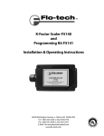
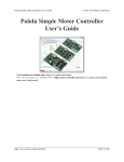
Please note that this guide applies to Pololu’s second-generation AVR programmer (pictured to the left below), not the
original, similar-looking Orangutan USB programmer [http://www.pololu.com/catalog/product/740] (pictured to the right).
USB AVR programmer PGM03A.
Orangutan USB programmer PGM02A/B.
If you have the original Orangutan USB programmer, you can find it’s user’s guide here [http://www.pololu.com/docs/0J6].
Important Safety Warning and Handling Procedures
The USB AVR programmer is not intended for young children! Younger users should use this product only under adult
supervision. By using this product, you agree not to hold Pololu liable for any injury or damage related to the use or
to the performance of this product. This product is not designed for, and should not be used in, applications where the
malfunction of the product could cause injury or damage. Please take note of these additional precautions:
• The USB AVR programmer contains lead, so follow appropriate handling procedures, such as washing hands after
handling.
• Since the PCB and its components are exposed, take standard precautions to protect your programmer from ESD
(electrostatic discharge), such as first touching the surface the programmer is resting on before picking it up. When
handing the programmer to another person, first touch their hand with your hand to equalize any charge imbalance
between you so that you don’t discharge through the programmer as the exchange is made.
1. Overview
Page 2 of 40
Pololu USB AVR Programmer User's Guide
© 2001–2010 Pololu Corporation
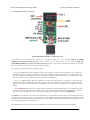
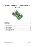
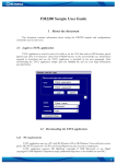
1.a. Module Pinout and Components
Pololu USB AVR programmer, labeled top view.
The Pololu USB AVR programmer connects to a computer’s USB port via an included USB A to mini-B
cable [http://www.pololu.com/catalog/product/1129], and it connects to the target device via an included 6-pin ISP
programming cable [http://www.pololu.com/catalog/product/972] (the older, 10-pin ISP connections are not directly supported,
but it is easy to create or purchase a 6-pin-to-10-pin ISP adapter).
The USB AVR programmer has three indicator LEDs:
• The green LED indicates the USB status of the device. When you connect the programmer to the computer via
the USB cable, the green LED will start blinking slowly. The blinking continues until it receives a particular message
from the computer indicating that the drivers are installed correctly. After the programmer gets this message, the
green LED will be on, but it will flicker briefly when there is USB activity.
• The yellow LED indicates that the programmer is doing something. When it is blinking, it means that the
programmer has detected the target device (the voltage on the target VDD line is high). When it is on solid, it means
that the SLO-scope is enabled, and lines A and B are used for the SLO-scope instead of the USB-to-TTL-serial
adapter.
• The red LED indicates an error or warning. When it is blinking, it means that the target device is not detected (the
voltage on the target VDD line is low). When it is on solid, it means that the last attempt at programming resulted in
an error. You can determine the source of the error by running the configuration utility (see Section 3.d).
The VBUS line provides direct access to the 5V VBUS line on the USB cable and can be used to power additional devices.
The line can provide up to 100 mA, so the current draw of your programmer plus any additional devices should not exceed
this amount. If you attempt to draw more than this limit, your computer might disconnect the USB port temporarily or take
other actions to limit the use of USB power.
The GND line provides direct access to the grounded line on the USB cable (and ground on the programmer).
1. Overview
Page 3 of 40
Pololu USB AVR Programmer User's Guide
© 2001–2010 Pololu Corporation
The TX and RX lines are the TTL serial port for the USB-to-TTL-serial adapter. They are labeled from the computer’s
perspective: TX is an output that connects to your target’s serial receive pin and RX is an input that connects to your
target’s serial transmit pin. Section 5 describes how to use these lines to communicate with your devices from the
computer.
The A and B lines can be used as serial control/handshaking lines for the USB-to-TTL-serial adapter (see Section 5.a) or
as analog voltage inputs for the SLO-scope (see Section 6).
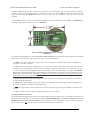
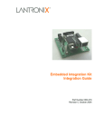
Pololu USB AVR programmer bottom view with
dimensions.
The USB AVR programmer has a standard 6-pin AVR ISP connector for programming AVRs, and the pins are labeled
on the silkscreen on the bottom side of the board. The pins on the connector are:
1. MISO: The “Master Input, Slave Output” line for SPI communication with the target AVR. The programmer is
the master, so this line is an input.
2. VDD: An input line that the programmer uses to measure the voltage of the target AVR. While programming
the target device, the programmer uses this line to constantly monitor the target VDD. If the voltage goes too low
or varies too much, then the programmer aborts programming in order to avoid damage to the target AVR. Section
3.d has more information about target VDD monitoring. The VDD line is not used to power the programmer; the
programmer is powered from the USB. This line cannot be used to power the target device; the target device must be
independently powered for programming to work.
3. SCK: The clock line for SPI communication with the target AVR. The programmer is the master, so this line is
an output during programming.
4. MOSI: The “Master Output, Slave Input” line for SPI communication with the target AVR. The programmer is
the master, so this line is an output during programming.
5. RST: The target AVR’s reset line. This line is used as an output driven low during programming to hold the AVR
in reset.
6. GND: Ground. This line should be connected to the target device’s ground.
1.b. Supported Microcontrollers
The Pololu USB AVR programmer should work with all AVRs that can be programmed by an AVR ISP, but it has not been
tested on all devices (it has been tested with all Orangutan robot controllers [http://www.pololu.com/catalog/category/8] and the
3pi Robot [http://www.pololu.com/catalog/product/975]). The programmer features upgradable firmware, allowing updates for
future devices. It does not currently work with Atmel’s line of XMega microcontrollers.
1. Overview
Page 4 of 40
Pololu USB AVR Programmer User's Guide
© 2001–2010 Pololu Corporation
The programmer is powered by the 5V USB power bus, and it is intended for programming AVRs that are running at close
to 5 V (note that the programmer does not deliver power to the target device).
1.c. Supported Operating Systems
The Pololu USB AVR programmer has been tested under Microsoft Windows XP, Windows Vista, Windows 7, and Linux.
It is not compatible with any version of the Mac OS or with older versions of Windows. Third-party programming software
exists for all operating systems.
The programer’s configuration utility works only in Windows, but this should not be a big problem for Linux users because
all the options that can be set in the configuration utility are stored in persistent memory, so you would only have to use
Windows when you want to change those parameters, which should be rarely (if ever). The programmer does not require
the configuration to program AVRs or to use the TX and RX USB-to-TTL-serial adapter pins.
The SLO-scope application works only in Windows.
1. Overview
Page 5 of 40
Pololu USB AVR Programmer User's Guide
© 2001–2010 Pololu Corporation
2. Contacting Pololu
You
can
check
the
Pololu
USB
AVR
programmer
page [http://www.pololu.com/catalog/product/1300] for additional information. We
would be delighted to hear from you about any of your projects and about your
experience with the Pololu USB AVR Programmer. You can contact
us [http://www.pololu.com/contact]
directly
or
post
on
our
forum [http://forum.pololu.com/]. Tell us what we did well, what we could improve,
what you would like to see in the future, or anything else you would like to say!
2. Contacting Pololu
Page 6 of 40
Pololu USB AVR Programmer User's Guide
© 2001–2010 Pololu Corporation
3. Getting Started in Windows
The Pololu USB AVR programmer works in Windows XP, Windows Vista, and Windows 7.
3.a. Installing Windows Drivers and the Configuration Utility
If you use Windows XP, you will need to have either Service Pack 3 [http://www.microsoft.com/downloads/
details.aspx?FamilyId=68C48DAD-BC34-40BE-8D85-6BB4F56F5110] or Hotfix KB918365 installed before
installing the drivers for the Pololu USB AVR programmer. Some users who installed the hotfix have
reported problems using the programmer which were solved by upgrading to Service Pack 3, so we
recommend Service Pack 3 over the hotfix.
Please note that these drivers will only work for the USB AVR programmer; if you have Pololu’s original Orangutan
USB programmer [http://www.pololu.com/catalog/product/740], you will need to install the drivers specific to that device.
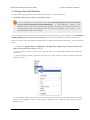
Before you connect your Pololu USB AVR programmer to a computer running Microsoft Windows, you must install its
drivers:
1. Download the pgm03a drivers, configuration, and SLO-scope software [http://www.pololu.com/file/download/
pgm03a_windows_091222.zip?file_id=0J198] (4988k zip)
2. Extract the files in pgm03a_windows.zip to a temporary directory by right-clicking on the ZIP file and selecting
“Extract All…”
3. Open the temporary directory, right click on pgm03a.inf and select “Install”. (Do not try to install the other INF
file in the directory.)
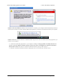
4. After selecting “Install”, Windows will warn you that the driver has not been tested by Microsoft and recommend
that you stop the installation. Click “Continue Anyway” (Windows XP) or “Install this driver software anyway”
(Windows Vista).
3. Getting Started in Windows
Page 7 of 40
Pololu USB AVR Programmer User's Guide
© 2001–2010 Pololu Corporation
Windows Vista and Windows 7 users: After the INF file is installed, your computer should automatically install the
necessary drivers when you connect a Pololu USB AVR programmer, in which case no further action from you is required.
Windows XP users: After the INF file is installed, follow steps 5-9 for each new Pololu USB AVR programmer you
connect to your computer.
5. Connect the USB AVR programmer to your computer’s USB port. The programmer is actually three devices
in one so your XP computer will detect all three of those new devices and display the “Found New Hardware
Wizard” three times. Each time the “Found New Hardware Wizard” pops up, follow steps 6-9.
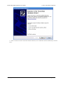
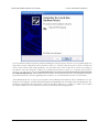
6. When the “Found New Hardware Wizard” is displayed, select “No, not this time” and click “Next”.
3. Getting Started in Windows
Page 8 of 40
Pololu USB AVR Programmer User's Guide
© 2001–2010 Pololu Corporation
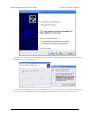
7. On the second screen of the “Found New Hardware Wizard”, select “Install the software automatically” and click
“Next”.
3. Getting Started in Windows
Page 9 of 40
Pololu USB AVR Programmer User's Guide
© 2001–2010 Pololu Corporation
8. Windows XP will warn you again that the driver has not been tested by Microsoft and recommend that you stop
the installation. Click “Continue Anyway”.
9. When you have finished the “Found New Hardware Wizard”, click “Finish”. After that, another wizard will pop
up. You will see a total of three wizards when plugging in the programmer. Follow steps 6-9 for each wizard.
3. Getting Started in Windows
Page 10 of 40
Pololu USB AVR Programmer User's Guide
© 2001–2010 Pololu Corporation
If you use Windows XP and experience problems installing the serial port drivers, the cause of your problems might be a
bug in older versions of Microsoft’s usb-to-serial driver usbser.sys. Versions of this driver prior to version 5.1.2600.2930
will not work with the USB AVR programmer. You can check what version of this driver you have by looking in
the “Details” tab of the “Properties” window for C:\Windows\System32\drivers\usbser.sys. To get the fixed version of
the driver, you will need to either install Service Pack 3 [http://www.microsoft.com/downloads/details.aspx?FamilyId=68C48DADBC34-40BE-8D85-6BB4F56F5110] or Hotfix KB918365. Some users who installed the hotfix have reported problems using the
programmer which were solved by upgrading to Service Pack 3, so we recommend Service Pack 3 over the hotfix.
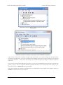
After installing the drivers, if you go to your computer’s Device Manager and expand the “Ports (COM & LPT)” list, you
should see two COM ports: “Pololu USB AVR Programmer Programming Port” and “Pololu USB AVR Programmer TTL
Serial Port”. In parentheses after these names, you will see the name of the port (e.g. “COM3” or “COM4”). If you expand
the “Pololu USB Devices” list you should see an entry for the Pololu USB AVR programmer.
3. Getting Started in Windows
Page 11 of 40
Pololu USB AVR Programmer User's Guide
© 2001–2010 Pololu Corporation
Windows XP device manager showing the Pololu USB AVR
Programmer
Windows Vista device manager showing the Pololu USB AVR Programmer
Some software will not allow connection to higher COM port numbers. If you need to change the COM port number
assigned to your USB device, you can do so using the Device Manager. Bring up the properties dialog for the COM port
and click the “Advanced…” button in the “Port Settings” tab. From this dialog you can change the COM port assigned do
your device.
Once your have successfully installed the device drivers, you can run the configuration utility that came in the ZIP file,
pgm03a_config.exe. This is a stand-alone Windows application that allows you to change many of the settings of your
programmer. Please see Section 3.d for more information.
This software package also contains the installation files for the Pololu SLO-scope application for Windows. Please see
Section 6 for installation and usage instructions.
3. Getting Started in Windows
Page 12 of 40
Pololu USB AVR Programmer User's Guide
© 2001–2010 Pololu Corporation
3.b. Programming AVRs Using AVR Studio
After you’ve installed the necessary drivers, the next step is to download and install a compiler.
WinAVR [http://winavr.sourceforge.net/] is an open source suite of software development tools for the Atmel AVR series
of microcontrollers. It includes the GNU GCC compiler for C and C++. Please follow the installation instructions they
provide.
WinAVR alone will give you all the tools you need to start programming AVRs with the USB AVR programmer, but
Atmel offers AVR Studio [http://www.atmel.com/avrstudio/], a free integrated development environment (IDE) designed to
work with the WinAVR GCC C/C++ compiler. AVR Studio includes a simulator and other useful tools, and supports the
AVR ISP protocol used by the Orangutan USB programmer. Please follow Atmel’s installation instructions. Note that
newer versions of AVR Studio might not work with older versions of WinAVR, so we recommend you upgrade to the
newest version WinAVR every time you get a new version of AVR Studio.
The following tutorial covers the steps needed to program AVRs using AVR Studio and a Pololu USB AVR programmer.
Specifically, we will write a simple program to blink an LED connected to pin PD1 of an AVR. On any of the
Orangutan robot controllers [http://www.pololu.com/catalog/category/8] and the 3pi Robot [http://www.pololu.com/catalog/product/
975], this program will blink the red user LED. If you want to program an AVR that does not have an LED connected to
pin PD1, the LED-blinker code in this tutorial will have no visible effect.
If you have an Orangutan or 3pi and want to jump straight in to using your USB AVR programmer, you can skip steps 1-3
by downloading the AVR Studio project these steps would create. Determine the microcontroller on your device, download
the corresponding file below, extract all the files to a directory, open the AVR Studio project file (BlinkLED.aps), and
proceed to step 4.
• mega48: BlinkLED_m48.zip [http://www.pololu.com/file/download/BlinkLED_m48.zip?file_id=0J188] (9k zip)
• mega168: BlinkLED_m168.zip [http://www.pololu.com/file/download/BlinkLED_m168.zip?file_id=0J189] (9k zip)
• mega328: BlinkLED_m328.zip [http://www.pololu.com/file/download/BlinkLED_m328.zip?file_id=0J190] (9k zip)
1.
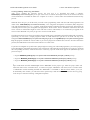
Open AVR Studio and click New Project. Select AVR GCC for the project type. Enter the project name and
initial file name. In the screenshot below, we named our project “BlinkLED” and elected to have a folder called
“C:\BlinkLED” created containing the blank file “BlinkLED.c”. Click Next >>. DO NOT click “Finish” yet. If you
do accidentally click “Finish”, you will not be able to perform step 2 and will instead have to set the device by going
to the “Project” menu and selecting “Configuration Options”.
3. Getting Started in Windows
Page 13 of 40
Pololu USB AVR Programmer User's Guide
© 2001–2010 Pololu Corporation
Creating a new AVR Studio project, step 1
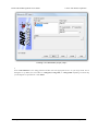
2.
Select AVR Simulator as the debug platform and then select the appropriate device for your target AVR. For an
Orangutan or 3pi Robot, this will either be ATmega48, ATmega168, or ATmega328P depending on which chip
your Orangutan or 3pi Robot has. Click Finish.
3. Getting Started in Windows
Page 14 of 40
Pololu USB AVR Programmer User's Guide
© 2001–2010 Pololu Corporation
Creating a new AVR Studio project, step 2
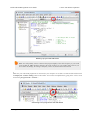
3.
Write your program in BlinkLED.c as seen in the screen shot below and click the Build button on the toolbar (or
press F7).
3. Getting Started in Windows
Page 15 of 40
Pololu USB AVR Programmer User's Guide
© 2001–2010 Pololu Corporation
Building a project with AVR Studio
Note: You will probably want to customize this program slightly if the clock frequency of your AVR
is not 20 MHz. F_CPU should be defined as the clock frequency of your AVR in units of Hz. If you
do not make this change, the timing of delayms() will be off, but the LED will still blink.
4.
Make sure your USB AVR programmer is connected to your computer via its USB A to mini-B cable and then click
the Display the ‘Connect’ Dialog button on the toolbar. You can also accomplish this by going to the “Tools” menu
and selecting Program AVR > Connect….
Connecting to the programmer with AVR Studio
3. Getting Started in Windows
Page 16 of 40
Pololu USB AVR Programmer User's Guide
© 2001–2010 Pololu Corporation
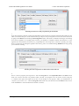
5.
This will bring up a programmer selection dialog. Select AVRISP as the platform. The USB AVR programmer uses
AVR ISP version 2, which is written as AVRISPv2. Please note that this is not the same as AVR ISP mkII. Select the
port name of your programmer if you know what it is, or select Auto and AVR Studio will try all the ports until it
detects the programmer. You can determine your programmer’s port name by looking in the “Ports (COM & LPT)”
list of your Device Manager for “Pololu USB AVR Programmer Programming Port”. Click “Connect…” to bring up
the ISP window.
AVR Studio’s programmer-selection dialog
If the ISP window does not appear when you click “Connect…”, your computer cannot detect the programmer. Please
see Troubleshooting (Section 7) for help identifying and fixing the problem.
If AVR Studio brings up a dialog asking if you want to upgrade (or downgrade) your programmer’s firmware, click
Cancel to ignore the message and use your programmer. To prevent this dialog from appearing in the future, use the
Configuration Utility (Section 3.d) to change the programmer’s hardware and software version numbers.
6.
Select the Main tab. In the dropdown box that lists AVR models, select the same device that you selected when you
created the project. For an Orangutan or 3pi Robot, this will either be ATmega48, ATmega168, or ATmega328P.
3. Getting Started in Windows
Page 17 of 40
Pololu USB AVR Programmer User's Guide
© 2001–2010 Pololu Corporation
Selecting the device for ISP programming in AVR Studio
7.
If you have not done so already, connect the programmer to the target device using the 6-pin ISP cable. Make sure the
cable is oriented so that pin 1 on the connector lines up with pin 1 on your target device! You can test the connection
by going to the Main tab and clicking the Read Signature button. This sends a command to the target AVR asking
for its device signature. If everything works correctly, you should see “Signature matches selected device”. If the
signature does not match the selected device, you probably have the wrong device selected (or possibly your target
device is turned off). If reading the signature fails entirely, please see Troubleshooting (Section 7) for help getting
your connection working.
Reading the device signature in AVR Studio’s Main ISP tab
8.
Now it is time to program your target device. Select the Program tab. Your Input HEX File in the Flash section
needs to be the hex file that was generated when you built your program. You can browse for this using the
"..." button to the right of the input file text box. If you navigate to your project’s folder, you should find it as
“default\<project name>.hex”. Click the Program button (make sure you click the one in the Flash section, not one
in the “EEPROM” or “ELF Production File Format” sections!).
3. Getting Started in Windows
Page 18 of 40
Pololu USB AVR Programmer User's Guide
© 2001–2010 Pololu Corporation
AVR Studio’s Program ISP tab
As your USB AVR programmer programs the AVR, you should see all three LEDs flicker and you should see the
following text appear at the bottom of the window:
Reading FLASH input file.. OK
Setting mode and device parameters.. OK!
Entering programming mode.. OK!
Erasing device.. OK!
Programming FLASH ..
OK!
Reading FLASH ..
OK!
FLASH contents is equal to file.. OK
Leaving programming mode.. OK!
If there were no problems, the LED connected to PD1 of your AVR should now be flashing! Note that if you are
trying this on a 3pi robot and you have not yet soldered in the optional through-hole LEDs, the flashing LED will be
3. Getting Started in Windows
Page 19 of 40
Pololu USB AVR Programmer User's Guide
© 2001–2010 Pololu Corporation
on the bottom of the robot. If there was a problem, please see Troubleshooting (Section 7) for help identifying and
fixing it.
3.b.1. Using Advanced Features of AVR Studio
This section provides a brief overview of the programming features of AVR Studio that were not covered in Section 3.b.
You will not typically need to use of these advanced features, but it is good to know about them for the rare occasions when
you will need them. Please see the Atmel’s AVR Studio documentation for more detailed descriptions of these features.
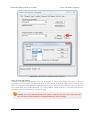
ISP Frequency
In the ISP window, under the Main tab, the Programming Mode and Target Settings section lets you set the frequency
of the clock used when programming the target device. The higher the ISP frequency, the faster the target AVR will be
programmed, but this frequency must be less than a quarter of the target AVR’s clock frequency. Click Read to read the
frequency from the programmer and click Write to write the selected frequency to the programmer. It is important to
note that the frequencies in the ISP Freq list are not correct when you are using the Pololu USB AVR programmer. See
Section 3.d for a list of the actual frequencies and more information about selecting the ISP frequency.
3. Getting Started in Windows
Page 20 of 40
Pololu USB AVR Programmer User's Guide
© 2001–2010 Pololu Corporation
AVR Studio’s interface for setting the ISP frequency.
Fuses (proceed with caution!)
Clicking on the Fuses tab automatically causes the programmer to read the fuse settings of the target AVR. If the
programmer is not connected to the target AVR when you select this tab, AVR Studio displays an error message. Fuses
allow you to configure certain persistent, fundamental aspects of your AVR such as boot flash size, brown-out detection
level, and the clock off of which it should run (e.g. external crystal or internal oscillator). To learn more about the fuses
and what they do, see the datasheet for your specific AVR.
Warning: You can permanently disable your AVR by setting the fuses incorrectly. Only advanced
users who know precisely what they are doing should change the fuse settings!
3. Getting Started in Windows
Page 21 of 40
Pololu USB AVR Programmer User's Guide
© 2001–2010 Pololu Corporation
Lock Bits
Clicking on the Lock Bits tab automatically causes the programmer to read the lock bits of the target AVR. If the
programmer is not connected to the target AVR when you select this tab, AVR Studio displays an error message. Lock bits
allow you to secure your AVR by preventing further flash writing or reading. The lock bits can be reset to a fully unlocked
state by performing a chip erase (i.e. by clicking the Erase Device button in the Main tab). Lock bits are usually only
important if you wish to release a product to other people without giving them access to the program it is running, or if
you wish to make it slightly more difficult to overwrite a programmed chip.
3.c. Programming AVRs Using AVRDUDE
It is possible to program AVRs in Windows using AVRDUDE [http://www.bsdhome.com/avrdude/]. AVRDUDE is free and
included in the WinAVR [http://winavr.sourceforge.net/] package. To program a hex file on to your AVR, you would type
something similar to the following into a command prompt:
cd C:\BlinkLED\default
avrdude -p m168 -P COM2 -c avrispv2 -e -U flash:w:BlinkLED.hex
• The argument following the -p is the part number of the AVR. For an Orangutan or 3pi Robot, the part number
should be m328p, m168, or m48.
• The argument following the -P is the port name. You can determine your programmer’s port name by looking in
the “Ports (COM & LPT)” list of your Device Manager for “Pololu USB AVR Programmer Programming Port”.
• The argument following the -c is the programmer protocol and should be avrispv2.
• The -e option requests an initial chip erase.
• The -U option is used for writing, reading, or verifying flash, EEPROM, fuses, or lock bits. In this example we are
using -U to write BlinkLED.hex to flash.
Please see the AVRDUDE documentation [http://www.nongnu.org/avrdude/user-manual/avrdude.html] for more detailed
information.
3.d. Configuring the Programmer
The Pololu USB AVR programmer can be configured using the Pololu USB AVR Programmer Configuration Utility for
Windows. The utility comes with the Windows drivers (Section 3.a) and can be run by double clicking on the executable
pgm03a_config.exe. This section describes all the available settings and what they do.
3. Getting Started in Windows
Page 22 of 40
Pololu USB AVR Programmer User's Guide
© 2001–2010 Pololu Corporation
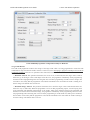
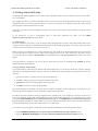
Pololu USB AVR programmer configuration utility for Windows.
Target VDD Monitor
The USB AVR programmer monitors the voltage of the target AVR while it is being programmed to ensure that ISP
commands are only sent when the AVR’s VDD is at a safe level, since attempting to program an underpowered AVR can
permanently disable it. There are two parameters that control this feature:
• Minimum Allowed: This parameter determines the lowest level (in millivolts) that the target AVR’s VDD is
allowed to go. If the target AVR’s VDD drops below this level, the programmer immediately aborts programming
and turns on the red programming LED. Lowering this value will allow programming of AVRs at lower voltages, but
will make it more likely that the programmer will send ISP commands to the AVR while the AVR is running at an
unsafe voltage. The default value is 4384 mV.
• Maximum Range Allowed: This parameter determines how much the target AVR’s VDD measurements are
allowed to vary (in millivolts). When the programmer recieves an ISP programming request, it starts keeping track
of the maximum and minimum measurements of the AVR’s VDD. If the difference between the maximum and
minimum exceeds the allowed maximum range, the programmer immediately aborts programming and turns on the
red programming LED. Increasing this value will allow programming of AVRs under less stable power conditions,
but will make it more likely that the programmer will send ISP commands to the AVR while the AVR is running at
an unsafe voltage. The default value is 512 mV.
3. Getting Started in Windows
Page 23 of 40
Pololu USB AVR Programmer User's Guide
© 2001–2010 Pololu Corporation
Measurements From Last Programming
This section displays the minimum and range of the target VDD measurements from the last time the programmer was in
programming mode or tried to enter programming mode. This can help determine whether programming problems are due
to the target’s power supply.
Error From Last Programming
When an error or unexpected condition causes the programmer to leave programming mode, or fail to enter programming
mode, then the programmer turns on the red LED and records the error code. A description of the error can be found here.
See Troubleshooting (Section 7) for details on specific error messages.
ISP Frequency
The higher the ISP frequency, the faster you can program the target AVR, but the ISP frequency must be less than a quarter
of the target AVR’s clock frequency.
The ISP frequency can be set in AVR Studio (see Section 3.b.1) as well as in the Configuration Utility, but the frequencies
listed in the AVR Studio user interface do not match the actual frequencies used by the Pololu USB AVR programmer.
Frequency Listed
Allowed Target
Actual Frequency
in AVR Studio
Frequency
1.845 MHz
2000 kHz
> 8 MHz
460.8 kHz
1500 kHz
> 6 MHz
115.2 kHz
750 kHz
> 3 MHz
57.6 kHz
200 kHz
> 800 kHz
4.00 kHz
4.0 kHz
> 16 kHz
1.21 kHz*
1.5 kHz*
> 6 kHz
* This ISP frequency is so low that AVR Studio times out while attempting to program flash or EEPROM pages, but it can
be used to program fuses and lock bits on AVRs running at frequencies as low as 6 kHz.
An AVR running at 20 MHz or higher (e.g. the Orangutan SV-xx8, Orangutan LV-168, Baby Orangutan, and 3pi robot)
can be programmed at 2000 kHz (1.845 MHz in AVR Studio), which is the fastest setting.
An AVR running at 8 MHz or higher (e.g. the original Orangutan) can be programmed at 1500 kHz (460.8 kHz in AVR
Studio).
An AVR running at 1 MHz, such as one clocked off of the internal RC oscillator with the divide-by-8 fuse bit programmed,
can be programmed at an ISP frequency as high as 200 kHz (57.6 kHz in AVR Studio). This is the USB AVR
programmer’s default ISP frequency.
The two lowest frequencies support AVRs with a clock frequency under 1 MHz. The 1.5 kHz setting is too slow to actually
program the flash or EEPROM on your target device using AVR Studio (it will timeout while attempting to program the
flash/EEPROM pages), but it will still let you set the fuses. Be aware that if you attempt to program flash or EEPROM at
4.0 kHz, it might take five minutes or longer to program a 16KB of flash, so we only recommend this ISP frequency for
putting small programs on very low-frequency AVRs.
Serial Number
This is a unique identifier assigned to this programmer by Pololu. This number can not be changed.
3. Getting Started in Windows
Page 24 of 40
Pololu USB AVR Programmer User's Guide
© 2001–2010 Pololu Corporation
TTL Serial Port
This section is used to identify pins A and B with serial handshaking lines so that they can be used as general purpose user
I/O lines. See Section 5.a.
AVR ISP Emulation
This section is used to change the hardware and software version numbers of the programmer. These numbers are read by
AVR Studio when it connects to the programmer and are expressed in hex. If these numbers do not match the numbers that
AVR Studio expects, then it brings up a dialog asking if you want to upgrade (or downgrade) your programmer’s firmware;
the Pololu AVR USB programmer does not support this method of firmware upgrading, so this dialog is nothing more than
a nuisance to those not using an Atmel programmer. You should click Cancel to ignore the message and proceed to the
AVRISP programming dialog. To prevent this firmware-upgrade dialog from appearing in the future, set the numbers here
to the numbers that AVR Studio says it expects.
3. Getting Started in Windows
Page 25 of 40
Pololu USB AVR Programmer User's Guide
© 2001–2010 Pololu Corporation
4. Getting Started in Linux
The Pololu USB AVR programmer can be used in Linux to program AVRs and to send and receive bytes on the USB-toTTL-serial adapter.
The configuration utility is written for Windows; there is no Linux version. All of the parameters that can be set in the
configuration utility are stored in persistent memory, so Linux users only have to use Windows when they want to change
those parameters, which should not be too often.
The SLO-scope client is written for Windows, and there is no Linux version; Linux users are unable to use the SLO-scope
at this time.
If you would like to write a configuration utility or SLO-scope application for Linux, you can contact
us [http://www.pololu.com/contact] for information.
4.a. Linux Driver
No driver installation is necessary to use the Pololu USB AVR Programmer in Linux. The Linux Kernel comes with a
USB-to-serial driver (the cdc_acm module) that automatically works with the programmer. (The source code for this driver
is in the kernel source under drivers/usb/class/cdc-acm.c.)
When you plug your programmer in to a Linux computer, the CDC ACM driver should automatically detect it and create
two serial port devices. Unless you have other devices plugged in that use the CDC ACM driver, the names of these
two serial port devices should be /dev/ttyACM0 for the programming port and /dev/ttyACM1 for the USB-to-TTL-serial
adapter.
If the programmer is plugged in, but you do not see these devices, please see Troubleshooting (Section 7) for help
identifying and fixing the problem.
4.b. Programming AVRs in Linux
To program AVRs in Linux using the Pololu USB AVR Programmer, you will need to install four software packages,
which can be downloaded from their respective websites. In Ubuntu Linux, these packages are provided in the “Universe”
repository.
1. gcc-avr: the GNU C compiler, ported to the AVR architecture
2. avr-libc: a library giving access to special functions of the AVR
3. binutils-avr: tools for converting object code into hex files
4. avrdude: the software to drive the programmer
Once these packages are installed, you will be able to compile C programs for the AVR with gcc to produce hex files.
These hex files can be loaded on to your AVR using avrdude and a programmer.
We will not go into the details of writing C programs for the AVR here, but, as an example, we will show you how to use
your Linux computer and the USB AVR Programmer to make an LED connected to PD1 of an AVR blink. On any of the
Orangutan robot controllers [http://www.pololu.com/catalog/category/8] and the 3pi Robot [http://www.pololu.com/catalog/product/
975], this program will blink the red user LED. If you want to program an AVR that does not have an LED connected to
pin PD1, the LED-blinker code in this tutorial will have no visible effect.
If your device is an ATmega48, ATmega168, or ATmega328P, download the corresponding archive below:
• mega48: BlinkLED_m48.zip [http://www.pololu.com/file/download/BlinkLED_m48.zip?file_id=0J188] (9k zip)
• mega168: BlinkLED_m168.zip [http://www.pololu.com/file/download/BlinkLED_m168.zip?file_id=0J189] (9k zip)
4. Getting Started in Linux
Page 26 of 40
Pololu USB AVR Programmer User's Guide
© 2001–2010 Pololu Corporation
• mega328: BlinkLED_m328.zip [http://www.pololu.com/file/download/BlinkLED_m328.zip?file_id=0J190] (9k zip)
If your device is not one of the above, you will need to download one of the above archives and modify the makefile to
use your particular device.
Unpack the archive on your Linux computer. Copy the file BlinkLED/linux/Makefile into the BlinkLED/ directory. You
will need to edit this file. Change all instances of “/dev/ttyUSB0” to the name of the programming port device, usually
/dev/ttyACM0. Additionally, it may be necessary to change the settings at the beginning to reflect the locations where the
AVR utilities were installed.
Note: You will probably want to edit BlinkLED.c slightly if the clock frequency of your AVR is not
20 MHz. F_CPU should be defined as the clock frequency of your AVR in units of Hz. If you do not make
this change, the timing of delayms() will be off, but the LED will still blink.
At this point, you should be ready to compile the example program and load it on to the AVR. Plug in the programmer and
type make. You should see output like this:
/usr/bin/avr-gcc -g -Os -Wall -mcall-prologues -mmcu=atmega168
-c -o BlinkLED.o BlinkLED.c
/usr/bin/avr-gcc -g -Os -Wall -mcall-prologues -mmcu=atmega168 BlinkLED.o -o BlinkLED.obj
/usr/bin/avr-objcopy -R .eeprom -O ihex BlinkLED.obj BlinkLED.hex
/usr/bin/avrdude -c avrispv2 -p m168 -P /dev/ttyACM0 -e
avrdude: AVR device initialized and ready to accept instructions
Reading | ################################################## | 100% 0.08s
avrdude: Device signature = 0x1e9406
avrdude: erasing chip
avrdude: safemode: Fuses OK
avrdude done.
Thank you.
/usr/bin/avrdude -c avrispv2 -p m168 -P /dev/ttyACM0 -U flash:w:BlinkLED.hex
avrdude: stk500_2_ReceiveMessage(): timeout
avrdude: AVR device initialized and ready to accept instructions
Reading | ################################################## | 100% 0.03s
avrdude: Device signature = 0x1e9406
avrdude: NOTE: FLASH memory has been specified, an erase cycle will be performed
To disable this feature, specify the -D option.
avrdude: erasing chip
avrdude: reading input file "BlinkLED.hex"
avrdude: input file BlinkLED.hex auto detected as Intel Hex
avrdude: writing flash (224 bytes):
Writing | ################################################## | 100% 0.39s
avrdude:
avrdude:
avrdude:
avrdude:
avrdude:
avrdude:
224 bytes of flash written
verifying flash memory against BlinkLED.hex:
load data flash data from input file BlinkLED.hex:
input file BlinkLED.hex auto detected as Intel Hex
input file BlinkLED.hex contains 224 bytes
reading on-chip flash data:
Reading | ################################################## | 100% 0.05s
avrdude: verifying ...
avrdude: 224 bytes of flash verified
avrdude: safemode: Fuses OK
avrdude done.
Thank you.
rm BlinkLED.o BlinkLED.obj
4. Getting Started in Linux
Page 27 of 40
Pololu USB AVR Programmer User's Guide
© 2001–2010 Pololu Corporation
This output indicates the AVR was successfully programmed. The LED connected to PD1 of your AVR should now be
flashing! Note that if you are trying this on a 3pi robot and you have not yet soldered in the optional through-hole LEDs,
the flashing LED will be on the bottom of the robot. If there was a problem, please see Troubleshooting (Section 7) for
help identifying and fixing it.
4. Getting Started in Linux
Page 28 of 40
Pololu USB AVR Programmer User's Guide
© 2001–2010 Pololu Corporation
5. Communicating via the USB-to-TTL-Serial Adapter
One bonus feature of the Pololu USB AVR programmer is the USB-to-TTL-serial adapter, which can be used for
connecting microcontroller projects to a personal computer. The programmer’s drivers make the USB-to-TTL-serial
adapter look like a standard serial port to the operating system, allowing you to use existing terminal programs and
software that are designed to use serial ports. This feature is similar to the Pololu USB-to-serial
adapter [http://www.pololu.com/catalog/product/391] product, except the programmer has fewer control lines available and
transmits at 5 V.
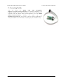
The TX and RX lines of the programmer are used to send asynchronous serial communication. When the programmer
receives a byte from the computer via USB, it will transmit that byte on the TX line. When the programmer receives a byte
on the RX input line, it will send that byte back to the computer via USB.
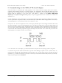
The bytes are sent and received eight bits at a time, with no parity and one stop bit. This coding is sometimes abbreviated
8N1. The bits must be non-inverted, meaning that a zero is sent as low voltage, and a one is sent as high voltage. All
devices involved in asynchronous serial communication need to agree ahead of time on the duration of one bit (the baud
rate), so all devices must be independently configured to run at the same baud rate before they will be able to communicate
with each other. The USB AVR programmer supports all integer baud rates from 110 to 115200 bits per second. The
following figure is an example of an 8N1 TTL serial byte:
To use the USB-to-TTL-serial adapter, you must first determine what port name the operating system has assigned it.
To determine the port name in Microsoft Windows, open the Device Manager, expand the “Ports (COM & LPT)” list,
and look for the “Pololu USB AVR Programmer TTL Serial Port” entry. The port name will be at the end of this line in
parentheses (e.g. “COM4”). In Windows, a given device will always be associated with the same port unless you manually
change its port assignment (see Section 3.a).
5. Communicating via the USB-to-TTL-Serial Adapter
Page 29 of 40
Pololu USB AVR Programmer User's Guide
© 2001–2010 Pololu Corporation
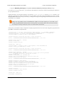
In Windows, the Device Manager shows which port name is assigned to the Pololu USB
AVR Programmer’s USB-to-TTL-serial adapter.
To determine the port name in Linux, type ls /dev/ttyACM*. The port name will be one of the devices listed there. If
there are only two ports, then the USB-to-TTL-serial adapter will be /dev/ttyACM1 (and the programming port will be
/dev/ttyACM0). If you see more than two ports, then you should look at the output from dmesg when you plug in the USB
AVR programmer to see which two ports are created; the second port is the USB-to-TTL-serial adapter. In Linux, the port
name depends on how many other devices are using the USB CDC ACM driver to create virtual serial ports at the time the
USB AVR Programmer is plugged in.
The USB AVR Programmer’s two serial ports in
Linux.
After determining the port name, you can use any serial port software to communicate on that port.
There are many free terminal programs available, including PuTTY [http://www.chiark.greenend.org.uk/~sgtatham/putty/]
(Windows or Linux), Tera Term [http://hp.vector.co.jp/authors/VA002416/teraterm.html] (Windows), and Br@y
Terminal [http://braypp.googlepages.com/terminal] (Windows). Advanced users developing scripted applications may prefer
the free terminal program kermit [http://www.columbia.edu/kermit/]. To use any of these terminal programs with the USB-toTTL-serial adapter, you must specify the port name determined above and your desired baud rate. The characters you type
will be transmitted on the programmer’s TX line. Bytes received by the programmer on the RX line will be displayed on
the screen by the terminal program.
5. Communicating via the USB-to-TTL-Serial Adapter
Page 30 of 40
Pololu USB AVR Programmer User's Guide
© 2001–2010 Pololu Corporation
PuTTY is a free Windows terminal program that can send and receive bytes on a
serial port.
If you need to send and receive non-ASCII bytes, you can use the Pololu Serial Transmitter Utility for
Windows [http://www.pololu.com/docs/0J23].
You can also write a computer program to use the serial port. The freely available Microsoft .NET framework contains a
SerialPort class that makes it easy to read and write bytes from a serial port. Here is some example C# .NET code that
uses a serial port:
// Choose the port name and the baud rate.
System.IO.Ports.SerialPort port = new System.IO.Ports.SerialPort("COM4", 115200);
// Connect to the port.
port.Open();
// Transmit two bytes on the TX line: 1, 2
port.Write(new byte[]{1, 2}, 0, 2);
// Wait for a byte to be received on the RX line.
int response = port.ReadByte();
// Show the user what byte was received.
MessageBox.Show("Received byte: " + response);
// Disconnect from the port so that other programs can use it.
port.Close();
5.a. Communicating via the Serial Control Lines
In addition to transmitting bytes on the TX line and receiving bytes on the RX line, the USB-to-TTL-serial adapter can
use programmer pins A and B as serial handshaking lines of your choosing. Each pin can be configured as an input or an
output by identifying it with a serial handshaking line using the programmer’s configuration utility (see Section 3.d). The
table below shows which handshaking lines are available (CTS is not available because there is no provision for it in the
USB CDC ACM subclass).
Direction Name .NET System.IO.Ports.SerialPort member
Output
DTR
DtrEnable
Output
RTS
RtsEnable
Input
CD
CDHolding
Input
DSR
DsrHolding
Input
RI
N/A
5. Communicating via the USB-to-TTL-Serial Adapter
Page 31 of 40
Pololu USB AVR Programmer User's Guide
© 2001–2010 Pololu Corporation
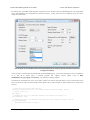
By default, pins A and B are high-impedance inputs that are not identified with any handshaking line. The programmer
stores the handshaking line configurations in persistent memory, so they only need to be configured when you want to
change the associations.
Pins A and B can be identified with serial handshaking lines using the Pololu USB AVR Programmer
Configuration Utility.
After your have associated pins A and/or B with serial handshaking lines, you can take advantage of the I/O capabilities
of A and B by either using a terminal program that supports control signals (such as Bray
Terminal [http://braypp.googlepages.com/terminal]) or by writing a computer program.
The Microsoft .NET framework is free to use and it contains a SerialPort class that makes it easy to read and write bytes
from a serial port as well as set and read the control signals. Here is some example C# .NET code that uses a serial port in
this way:
// Choose the port name and the baud rate.
System.IO.Ports.SerialPort port = new System.IO.Ports.SerialPort("COM4", 115200);
// Connect to the port.
port.Open();
// Assuming that line A is identified with RTS, this drives line A high (5 V).
port.RtsEnable = true;
// Assuming that line B is identified with DSR, this takes a digital reading of line B.
if (port.DsrHolding)
{
MessageBox.Show("Line B is high.");
}
5. Communicating via the USB-to-TTL-Serial Adapter
Page 32 of 40
Pololu USB AVR Programmer User's Guide
else
{
}
© 2001–2010 Pololu Corporation
MessageBox.Show("Line B is low.");
// Disconnect from the port so that other programs can use it.
port.Close();
When the SLO-scope feature is enabled, it assumes control of pins A and B and uses them as analog inputs
(or digital outputs controlled by the SLO-scope application). Pins A and B temporarily lose their serial
handshaking line associations while the SLO-scope is active, but these associations are restored once the
SLO-scope is disabled. You can disable the SLO-scope via the SLO-scope application or by unplugging the
programmer and plugging it back in.
5. Communicating via the USB-to-TTL-Serial Adapter
Page 33 of 40
Pololu USB AVR Programmer User's Guide
© 2001–2010 Pololu Corporation
6. Measuring Voltages Using the SLO-scope
A second bonus feature of the Pololu USB AVR programmer is the severely limited oscilloscope (SLO-scope), which uses
lines A and B as inputs to measure TTL-level voltages at a sample rate of up to 20 kHz. The SLO-scope has two operating
modes:
• Two 8-bit analog channels sampling at 10 kHz
• One 7-bit analog channel (A) and one digital channel (B) sampling at 20 kHz
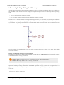
The SLO-scope can measure voltages between ground and approximately 5 V (depending on your computer’s USB bus
voltage); you can measure higher voltages by passing them through an external voltage divider before connecting them to
the programmer. The following schematic shows a general voltage divider circuit that can be used to scale down an input
signal to the SLO-scope’s required 0 – 5 V range:
The total resistance of R1+R2 should be as large as possible to minimize the divider’s effect on your signal, but it should
not exceed 100 kΩ or so.
Installing and Runing the Pololu SLO-scope Application
The SLO-scope application for Windows comes with the Windows drivers (Section 3.a) and can be installed by running
the installation batch file sloscope_installer.bat.
Windows Vista: right click on sloscope_installer.bat and select “Run as administrator”.
Windows XP: simply double click on sloscope_installer.bat.
At this time, the SLO-scope can only be used under the Windows operating system. Once installation is complete, the
application should begin running automatically. Note that the application will give you an error message and close if a
programmer is not connected to your computer. To start the SLO-scope application yourself, open the Start menu and
navigate to:
All Programs > Pololu > SLO-scope
6. Measuring Voltages Using the SLO-scope
Page 34 of 40
Pololu USB AVR Programmer User's Guide
© 2001–2010 Pololu Corporation
The SLO-scope application was written as a Visual C# 2008 project: SLO-scope client C# source
code [http://www.pololu.com/file/download/sloscope_client_100330.zip?file_id=0J335] (56k zip)
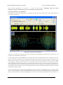
Using the Pololu SLO-scope Application
This application connects to the programmer, streams data from the SLO-scope, and provides the basic functionality of a
10 or 20 kHz oscilloscope.
Pololu SLO-scope client for Windows.
Controls are available for setting the SLO-scope operating mode, adjusting the horizontal and vertical scales, and
configuring lines A and B as digital outputs.
To start capturing data, click the Run button in the upper right corner. If the horizontal scale is such that it takes more
than 200 ms of data to fill the lower SLO-scope pane, the data will continuously stream across the pane. If the lower pane
displays 200 ms of data or less, the pane will draw all of its data at once when it has enough new data to warrant an update
(or, if triggering is enabled, when the trigger event is satisfied). In this latter time domain, you can enable the persistence
feature (check the Persistence checkbox) to cause the data on the screen to fade out over time when the next update occurs.
The Length parameter determines how long it takes for the data to fade. The upper SLO-scope pane shows a summary of
all of the data currently stored in memory. This is approximately 10 seconds of data when running at 10 kHz and 5 seconds
of data when running at 20 kHz.
To review the captured data in detail, click the Stop button (in the same place that the Run previously occupied). When
the SLO-scope is stopped, you can scroll through the data stored in memory by clicking on the portion of the upper pane
that you want to inspect or by clicking and dragging the cursor in the lower pane to pan through the data more finely. You
6. Measuring Voltages Using the SLO-scope
Page 35 of 40
Pololu USB AVR Programmer User's Guide
© 2001–2010 Pololu Corporation
can zoom in and out by changing the horizontal scale, and you can inspect the data in the lower pane by hovering over it
with your cursor. A purple rectangle highlights the portion of the upper pane is visible in the lower pane.
You can adjust the vertical scaling of a channel’s data by changing its volts-per-division parameter, and you can adjust the
amount of data that is shown in the lower pane by changing the SLO-scope’s milliseconds-per-division (horizontal scale)
parameter.
Triggering can be used when horizontal scaling is 20 ms/div or less. You can trigger on rising or falling edges of either
channel A or channel B, and you can adjust the trigger level by directly setting the value in millivolts or by dragging the
trigger level scrollbar on the right side of the lower pane to the desired position. When triggering is enabled, the data in the
lower pane will update whenever a trigger event occurs. Triggering can help you to better identify and analyze periodic
signals (such as motor noise, PWMs, etc.) while the SLO-scope is running.
To change the color used to draw a channel’s data, double click on the colored square in either the Channel A or Channel
B box.
To change the vertical position of the 0V level of a channel, click and drag that channel’s corresponding 0V-indicator
triangle on the left side of the lower pane.
While the SLO-scope is running, lines A and B do not function as serial handshaking lines as discussed in Section 5.a.
Rather, the SLO-scope can control the I/O states of A and B. The SLO-scope application lets you configure these pins as
inputs (their default settings when you first enable the SLO-scope) or as digital outputs driven high or low.
6. Measuring Voltages Using the SLO-scope
Page 36 of 40
Pololu USB AVR Programmer User's Guide
© 2001–2010 Pololu Corporation
7. Troubleshooting
This section helps solve problems you might have using the Pololu USB AVR programmer.
If the computer fails to connect to the programmer:
• Make sure your programmer is connected to your computer via a USB A to mini-B cable. If the programmer was
previously working and has since stopped, try closing all programs using the programmer (the configuration utility,
the SLO-scope client, and the AVR Studio ISP dialog), and cycle the power by unplugging it from your computer and
then reconnecting it.
• If you are in Windows, make sure you have installed the drivers the programmer needs to operate. Section 3.a
describes how to install the drivers in Windows.
• Is the programmer’s green USB status LED on? This is the LED next to the USB mini-B connector. If this LED is
blinking, then your drivers are not properly installed.
• If you are in Windows, can you see your programmer listed in the Device Manager? The Device Manager should
show three devices: under “Pololu USB Devices” should be “Pololu USB AVR Programmer”, and under “Ports
(COM & LPT)” should be “Pololu USB AVR Programmer Programming Port” and “Pololu USB AVR Programmer
TTL Serial Port” and there should be no error symbols on the icons representing these devices.
• If you are in Linux, check that /dev/ttyACM0 and /dev/ttyACM1 exist. If they do not, see the section below.
• Your computer will only let one program at a time have a given COM port open. If you are connected to your
programmer’s programming port using another program, such as a terminal or a second instance of AVR Studio,
you will not be able to connect to that same COM port with your programming software. Please make sure you do
not have any terminal programs connected to your programmer’s programming port. If you have multiple versions
of AVR Studio running, make sure that you have closed the ISP programming dialogs in all of them. When the ISP
dialog is open, that instance of AVR Studio has an open connection to your programmer’s programming port.
• If you are using AVR Studio, try connecting to your programmer’s specific COM port instead of selecting the
“Auto” option, which attempts to locate the port automatically. Some versions of AVR Studio fail to automatically
programmers on virtual COMs port that are too high (e.g. above COM9). If your programming COM port is too high
to select from the connection dialog box and AVR Studio does not automatically detect the programmer, you will
need to reassign the programming port to a lower virtual COM port. You can do this by opening the properties dialog
of the “Pololu USB AVR Programming Port” (found in the “Ports (COM & LPT)” section of the Device Manager)
and clicking the “Advanced…” button under the “Port Settings” tab.
If the programmer has problems connecting to the target AVR:
• The most common cause for this problem is an incorrect connection between your programmer and your target
device. If the ISP pins are misaligned between the programmer and the target AVR, the two will not be able to
communicate. Please make sure that the ISP pins as numbered in Section 1.a are correctly connected between your
AVR and your programmer (i.e. 1 goes to 1, 2 goes to 2, etc.).
• The target AVR must be powered for programming to work. Please make sure that your target device has power
and is turned on.
• If the target AVR is running at a voltage lower than 5 V, you may need to decrease the minimum allowed target
VDD setting using the configuration utility (Section 3.d). The default minimum allowed target VDD setting is too
high to allow the programmer to program at low voltages. Please note that you might need to take additional special
steps to safely program an AVR that is running off of a voltage below VUSB-0.5 V.
• Your programmer’s ISP frequency must be less than a quarter of your target AVR’s clock frequency. If you are
having trouble communicating with your target AVR, try lowering the ISP frequency using configuration utility
(Section 3.d) or the Main tab of AVR Studio’s ISP dialog (Section 3.b.1).
• If the red error LED is on, then run the configuration utility (Section 3.d) to determine the cause of the error.
7. Troubleshooting
Page 37 of 40
Pololu USB AVR Programmer User's Guide
© 2001–2010 Pololu Corporation
• There may be a problem with the target device. It is possible to kill a device with a static shock, by incorrectly
connecting power, or by programming the fuses incorrectly. There could also be a short or cut trace somewhere
on your target device. The ideal way to test for this is to try programming a different device with your USB AVR
programmer, or try using a different programmer to program your target device. If this is not an option, try verifying
that the target device is still functional and perform some continuity tests to check for shorts or disconnections on the
ISP programming lines. Don’t forget to check the 6-pin ISP cable for shorts as well.
If /dev/ttyACM0 or /dev/ttyACM1 do not exist in Linux:
• Try closing all programs using the programmer, unplugging the programmer, and plugging it back in.
• If the programmer is connected, the
1ffb:0081):
lsusb
command should output a line like this (the important thing is the
Bus 002 Device 002: ID 1ffb:0081
• If the CDC ACM driver detected the programmer when it was plugged in, then the dmesg command should have
some output like this:
[
26.378771] /build/buildd/linux-2.6.24/drivers/usb/class/cdc-acm.c: This
device cannot do calls on its own. It is no modem.
[
26.380858] cdc_acm 2-1:1.0: ttyACM0: USB ACM device
[
26.413512] /build/buildd/linux-2.6.24/drivers/usb/class/cdc-acm.c: This
device cannot do calls on its own. It is no modem.
[
26.413542] cdc_acm 2-1:1.2: ttyACM1: USB ACM device
[
26.421314] usbcore: registered new interface driver cdc_acm
[
26.421333] /build/buildd/linux-2.6.24/drivers/usb/class/cdc-acm.c: v0.25:USB
Abstract Control Model driver for USB modems and ISDN adapters
• If the CDC ACM driver is associated with both serial ports of the programmer, then the /dev/bus/usb/devices
file (or /proc/bus/usb/devices) should have a group of lines like this (the important thing is that Driver=cdc_acm
should appear in four places):
T:
D:
P:
S:
S:
S:
C:*
A:
A:
I:*
E:
I:*
E:
E:
I:*
E:
I:*
E:
E:
I:*
E:
Bus=02 Lev=01 Prnt=01 Port=00 Cnt=01 Dev#= 2 Spd=12 MxCh= 0
Ver= 2.00 Cls=ef(unk. ) Sub=02 Prot=01 MxPS= 8 #Cfgs= 1
Vendor=1ffb ProdID=0081 Rev= 0.01
Manufacturer=Pololu Corporation
Product=Pololu USB AVR Programmer
SerialNumber=00000005
#Ifs= 5 Cfg#= 1 Atr=80 MxPwr=100mA
FirstIf#= 0 IfCount= 2 Cls=02(comm.) Sub=02 Prot=01
FirstIf#= 2 IfCount= 2 Cls=02(comm.) Sub=02 Prot=01
If#= 0 Alt= 0 #EPs= 1 Cls=02(comm.) Sub=02 Prot=01 Driver=cdc_acm
Ad=81(I) Atr=03(Int.) MxPS= 10 Ivl=1ms
If#= 1 Alt= 0 #EPs= 2 Cls=0a(data ) Sub=00 Prot=00 Driver=cdc_acm
Ad=02(O) Atr=02(Bulk) MxPS=
8 Ivl=0ms
Ad=82(I) Atr=02(Bulk) MxPS=
8 Ivl=0ms
If#= 2 Alt= 0 #EPs= 1 Cls=02(comm.) Sub=02 Prot=01 Driver=cdc_acm
Ad=83(I) Atr=03(Int.) MxPS= 10 Ivl=1ms
If#= 3 Alt= 0 #EPs= 2 Cls=0a(data ) Sub=00 Prot=00 Driver=cdc_acm
Ad=04(O) Atr=02(Bulk) MxPS=
8 Ivl=0ms
Ad=84(I) Atr=02(Bulk) MxPS=
8 Ivl=0ms
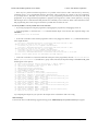
If#= 4 Alt= 0 #EPs= 1 Cls=ff(vend.) Sub=01 Prot=01 Driver=(none)
Ad=85(I) Atr=03(Int.) MxPS= 22 Ivl=1ms
Try comparing the outputs on your system to the outputs above to determine what went wrong.
Still need help?
If none of the above troubleshooting suggestions help, please contact us [http://www.pololu.com/contact] for support.
7. Troubleshooting
Page 38 of 40
Pololu USB AVR Programmer User's Guide
© 2001–2010 Pololu Corporation
8. Upgrading Firmware
The program that runs on the USB AVR Programmer (the firmware) can be upgraded with bug fixes or new features.
Version 1.01 (revision code 0101) of the firmware fixes two bugs with the TTL serial port (the RX and
TX lines). If you use the TTL serial port, we recommend that you upgrade to this version so that these bugs
will not cause you any problems. If you do not use the TTL serial port (you only use the programmer to
program AVRs and run the SLO-scope), then you do not need to upgrade.
Firmware Release Notes
Firmware version 1.00 (revision code 0001) is the original firmware for the programmer, released in June 2009. All
programmers that shipped before for December 17th, 2009 were shipped with this version.
Firmware version 1.01 (revision code 0101) was released on December 17th, 2009. This version contains two bug fixes
related to the programmer’s TTL serial port.
Determining your firmware version
You can determine the firmware version of your programmer either by compiling and running the command-line utility
PgmCmd (available in the Pololu USB Software Development Kit) or by following the steps below to determine the
programmer’s revision code.
To determine the programmer’s revision code in Windows:
1. Open up the Device Manager.
2. Double click on the “Pololu USB AVR Programmer” entry in the “Pololu USB Devices” list.
3. In the Details tab, select the “Hardware Ids” property in the dropdown box.
4. The first value displayed should be something like USB\VID_1FFB&PID_0081&REV_0101&MI_04. The number after
the REV_ is your revision code. If the revision code is “0001” then you have firmware version 1.00. If the revision
code is “0101” then you have firmware version 1.01.
To determine the programmer’s revision code in Linux:
1. Connect the programmer to your computer via USB.
2. Run the following command: lsusb
-v -d 1ffb:0081 | grep bcdDevice
This should output a line that has a number on it. That number is the revision code. If the revision code is “0.01” then you
have firmware version 1.00. If the revision code is “1.01”, then you have firmware version 1.01.
Upgrading firmware
To upgrade your programmer’s firmware, follow these steps:
1. If you have changed any of the programmer’s settings in the configuration utility or with
current settings because the firmware upgrade process will reset the settings.
PgmCmd,
record your
2. Download the latest version of the firmware here:
◦ Firmware version 1.01 for the USB AVR Programmer [http://www.pololu.com/file/download/
pgm03a_v1.01.pgm?file_id=0J316] (34k pgm) — released December 17th, 2009.
3. Get your programmer in to bootloader mode. In Windows, this can be done by clicking the “Start Bootloader”
button in the lower left corner of the configuration utility. In Linux or Windows, this can be done by running PgmCmd
8. Upgrading Firmware
Page 39 of 40
Pololu USB AVR Programmer User's Guide
© 2001–2010 Pololu Corporation
--bootloader.
The programmer will now disconnect itself from your computer and reappear as a new device called
“Pololu pgm03a Bootloader”.
◦ Windows 7, Vista and Linux: The driver for the bootloader will automatically be installed.
◦ Windows XP: When the “Found New Hardware Wizard” is displayed, follow steps 6–8 in Section 3.a to get
the driver working.
4. Once the bootloader’s drivers are properly installed, the green LED should be blinking in a double heart-beat
pattern, and there should be an entry for the bootloader in the “Ports (COM & LPT)” list of your computer’s Device
Manager in Windows.
5. Use a terminal program (such as Br@y Terminal [http://sites.google.com/site/terminalbpp/]) to connect to the
bootloader’s virtual serial port. In Windows, you can determine the port name of the bootloader (e.g. COM5) by
looking in the Device Manager. In Linux, you can determine the port name (e.g. /dev/ttyACM0) by running dmesg.
You can use any baud rate.
6. Type the following lower-case letters in to your terminal program to send them to the bootloader: fwbootload.
After each letter is sent, the bootloader should echo back the upper-case version of that letter. After you have finished
typing this sequence, you should see “FWBOOTLOAD” as the output from the bootloader in your terminal program,
and the programmer’s yellow LED should be on.
7. Now send lower-case “s”. The bootloader will spend a few seconds erasing the current firmware and settings, and
then it will echo back an upper-case S. Do not disconnect the programmer from the computer after this point until the
upgrade is complete.
8. Now send the contents of the downloaded firmware upgrade file to the bootloader. The firmware upgrade file is a
plain-text (ASCII) file, so you can open it in a text editor (such as notepad), copy the whole thing, and then paste it in
to your terminal program. Br@y terminal has a “Send File” button you can use.
9. While the file is being sent, the bootloader will echo back period characters (“….”). This process will take about
5 seconds. When the firmware upgrade is complete, the bootloader should echo back a pipe character (“|”) and turn
the red LED on.
10. You can now unplug your programmer and plug it back in to the computer and use the new firmware.
If you run into problems during a firmware upgrade, please contact us [http://www.pololu.com/contact] for assistance.
8. Upgrading Firmware
Page 40 of 40