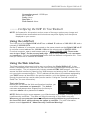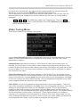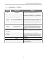
1
Table of Content
INTRODUCTION .............................................................................................. 2
FEATURES....................................................................................................... 2
BEFORE YOU BEGIN...................................................................................... 2
Package Contents.......................................................................................................... 2
Required Cables and Hardware .................................................................................... 2
Optional.......................................................................................................................... 2
QUICK START GUIDE ..................................................................................... 3
INSTALLING THE DIGITAL KVM VIA IP ........................................................ 9
Disabling Mouse Acceleration on the Managed Computers........................................ 10
NETWORK CONFIGURATION METHODS EXPLAINED.............................. 10
Web Configuration Using DHCP.................................................................................. 10
Terminal Configuration Using a Serial Cable............................................................... 11
CONFIGURING THE KVM FOR YOUR NETWORK...................................... 12
Using the LAN Port ...................................................................................................... 12
Using the Web Interface .............................................................................................. 12
Using the Terminal Interface via Serial Port ................................................................ 18
ACCESSING THE VNC INTERFACE ............................................................ 19
Web Interface............................................................................................................... 19
Native VNC Client ........................................................................................................ 20
SSH Tunnel (with Native VNC client) .......................................................................... 20
USING THE VNC MENU ................................................................................ 21
Welcome Window ........................................................................................................ 21
Bribar Feature .............................................................................................................. 21
Main Menu ................................................................................................................... 22
VirtKeys Menu.............................................................................................................. 23
Video Tuning Menu...................................................................................................... 24
ACCESSING KVM FEATURES ..................................................................... 25
Cascade Configuration ................................................................................................ 25
OSD Operations........................................................................................................... 26
Hot Key Commands..................................................................................................... 30
Selecting a Computer .......................................................................................... 30
Auto Scan ........................................................................................................... 30
Manual Scan ...................................................................................................... 30
Scan Rate ............................................................................................................ 31
Keyboard Typematic Rate ................................................................................... 31
Audio Stick ........................................................................................................... 31
Changing Your Configuration............................................................................... 31
TROUBLESHOOTING ................................................................................... 32
SPECIFICATIONS.......................................................................................... 35
SUPPORTED PROTOCOLS.......................................................................... 36
WARRANTY INFORMATION......................................................................... 37
REGULATORY COMPLIANCE STATEMENTS ............................................ 37
APPENDIX A: ABOUT SECURITY CERTIFICATE WARNINGS .................. 38
APPENDIX B: USING THE ADVANCED VIDEO TUNING FEATURE .......... 39
APPENDIX C: GETTING PEAK PERFORMANCE........................................ 41
APPENDIX D: USING OPTIONAL SERIAL SUPERVISOR DEVICES ......... 42
NOTE: Since firmware for our Digital KVM via IP Products is constantly evolving
to offer more functionality and improvements, some of the options and
instructions presented in this manual may differ from your unit. To obtain
the latest documentation and support information for our Digital KVM via
IP products, please visit www.rextron.com
MNIP/UNIP Series Digital KVM via IP
* Optional cables for PS/2 computers
CBM180H
CBM180UH
1-to-3 cable for PS/2 computer
1-to-2 cable for USB computer
1
MNIP/UNIP Series Digital KVM via IP
----- Introduction
Thank you for purchasing Rextron Digital KVM via IP series with integrated KVM. Using
the Internet or your TCP/IP enabled network, you can now remotely monitor and control
critical PC servers and workstations using an industry-standard Web browser or VNC client.
----- Features
Supports industry-standard networking and management protocols such as TCP/IP and
SNMP
Offers secure management options including SSL encryption, SSH tunneling, and
RADIUS authentication
Platform independent: can be managed using any Java-enabled Web browser
One remote management point for multiple computers
----- Before You Begin
This section describes the cables and other hardware that you may wish to use when setting
up and configuring your new Digital KVM via IP. We suggest you review this section
carefully before beginning the installation process.
Package Contents
Your package should contain the following:
1 x Digital KVM via IP unit
1 x Power Adapter
1 x AC Cord for Power Adapter
1 x User’s Manual
1 x Rack Mount kit of Standard 19” 1U ( for 8/16 ports only )
1 x Screw Package ( for 8/16 ports only )
CBM180H (PS/2 cable) or CBM180UH (USB cable) x 4/8/16-port Model ( depends on
the models )
One Set of Foot Pad
1 x DB9 RS-232 null modem serial cable ( optional )
Required Cables and Hardware
Depending on your needs, you may need one or more of the following cables:
1 x Ethernet cable (10/100 Mbits/sec Category 5 or better Ethernet cable)
Optional
There are many different lengths for PS/2 or USB cables available:
1.8, 3.0, 6.0, 10.0, 15.0 m
The Serial Supervisor -- Compatible with MNIP08 / MNIP16 /
UNIP04 / UNIP08 / UNIP16
2
MNIP/UNIP Series Digital KVM via IP
----- Quick Start Guide
For this Quick Start Guide, we offer three different easy step-by-step ways, letting you setup
this unit very quickly.
The First Way : If you don’t have DHCP (Dynamic Host Configuration
Protocol)
Step 1. Connect the CAT-5 cable to the LAN port on the rear panel of Digital KVM via IP.
And, connects the opposite end of the CAT-5 cable to the hub.
Step 2. Set the IP address of a computer connected on the same network as Digital KVM
via IP to a similar unused address like 192.168.1.124 and the subnet mask of
255.255.255.0.
a. Right click on "My Network Places", and select "Properties". You will get the
following screen:
3
MNIP/UNIP Series Digital KVM via IP
b. Right click on "Local Area Connection", and select "Properties" .
c. Double click on "Internet Protocol (TCP/IP)".
4
MNIP/UNIP Series Digital KVM via IP
d. Click “Advanced…” , then click “Add…” to add up the IP address of
“192.168.1.124”, and the Subnet mask of “255.255.255.0”.
Step 3. From that computer, open a web browser and go to https://192.168.1.123. Login
using "admin" for both username and password.
Step 4. Click on the Admin/Setup button then Network configuration (IP address,
netmask, gateway). From here you can set the IP address as needed.
The Second Way: If you have DHCP (Dynamic Host Configuration Protocol)
Step 1. Please have your MAC address. You can find it on a white sticker on the bottom of
the Digital KVM via IP. Here is an example, 00-0E-C5-00-08-1A.
Step 2. Power on the Digital KVM via IP and connected to the network via LAN port on the
rear panel. The DHCP will automatically assign an IP address for the Digital KVM
via IP.
Step 3. Access the DHCP log from your file server. A simple DHCP log looks similar to the
following:
5
MNIP/UNIP Series Digital KVM via IP
Step 4. From the above DHCP log, you can easily find the DHCP assigned an IP to the
Digital KVM via IP, 192.168.22.4. Once you have located this IP address, do NOT
power off the Digital KVM via IP or your DHCP server since it might lease a different
IP address.
Step 5. Simply open a web browser and type https://192.168.22.4 to access your Digital
KVM via IP. Login using “admin” for both username and password.
The Third Way: Using the HyperTerminal via Serial Port
Step 1. Connect the DB9 RS-232 null modem serial cable (optional) to the serial port on the
rear panel of Digital KVM via IP. And, connects the opposite end of the cable to the
serial port (COM1, COM2…) of your computer.
Step 2. From your computer, select “HyperTerminal” as following.
6
MNIP/UNIP Series Digital KVM via IP
Step 3. If you never setup your HyperTerminal before, it will ask you to input your phone
area code, please feel free to do so, and then click “OK”, you will get the following
screen. Please type any name you prefer, for example, “abc”.
Step 4. Choose the proper serial port you connect.
7
MNIP/UNIP Series Digital KVM via IP
Step 5. Change “Bits per second” to 115200.
Step 6. Press “Enter”, you will get the following screen.
Step 7. Follow the instruction on the screen. For example, simply type “I” for setting your IP,
type “M” for changing the machine name, and so on. Here is a reminder for you,
please type “W” after you made any change.
8
MNIP/UNIP Series Digital KVM via IP
----- Installing the Digital KVM via IP
DC 12V
(Power)
Serial
VGA Out
LAN Keybd/Mouse
Managed Computer (Non-Cascadable)
Managed Computer (Cascadable)
NOTE: The instructions here and elsewhere in the manual refer to port designations of the
UNIP/MNIP16, the 16-port version of the Digital KVM via IP. For other versions,
note the following:
UNIP/MNIP16: Ports PC 1~8/A~H
UNIP/MNIP08: Ports PC 1~8 only
UNIP/MNIP04: Ports PC 1~4 only
MNIP01: One Port Stand Alone
The restrictions on functions such as cascading and the assignment of master and
slave units also apply to all versions of the product.
1. Ensure that the Digital KVM via IP unit and the computers to be managed are powered
off.
2. If desired, mount the unit in a standardized rack or cabinet.
3. Connect a standard straight-through Ethernet patch cable to the LAN port on the rear
panel of the unit.
4. Connect the opposite end to your network hub, switch, or terminated wall outlet.
5. If you wish to use the product as a local console, connect a standard keyboard (purple
connector) and mouse (green connector) to the PS/2 ports, as marked on the rear panel.
6. Connect a VGA monitor to the video-out port on the rear panel of the unit.
7. (a) If you are using PS/2 connections to your managed computers, connect the end
of the CBM180H cable that has three connectors (keyboard, video, mouse) to the
keyboard, mouse, and VGA Out ports on a computer (often a server or other critical
system). Connect the opposite end (with a single VGA-style connector) to one of the PC
1~8/A~H ports on the rear panel of the Digital KVM via IP. Repeat this procedure for
each PS/2-enabled managed computer. You will be able to add additional managed
computers later with the Digital KVM via IP powered on.
(b) If you are using USB connections to your managed computers, connect the end
of the CBM180UH cable that has two connectors (USB, video) to an available USB port
and VGA Out port on the computer (often a server or other critical system). Connect the
opposite end (with a single VGA-style connector) to one of the PC 1~8/A~H ports on the
rear panel of the Digital KVM via IP. Repeat this procedure for each USB-enabled
managed computer. You will be able to add additional managed computers later with the
KVM powered on.
8. Power on the Digital KVM via IP by connecting the AC adapter to a suitable power
source and connecting the opposite end to the DC 12V port on the rear panel of the unit.
9. Power on each of the managed computers, observing normal startup procedures.
9
MNIP/UNIP Series Digital KVM via IP
NOTE: You can choose to mix managed computers connected via PS/2 and USB
connections as necessary with no impact on features or functionality.
NOTE: Steps 5 and 6 are necessary only if you wish to have the ability to manage the KVM
and its computers locally (i.e. not over the Internet or LAN). While not required,
adding these devices is highly recommended for ease of administration.
NOTE: The KVM also has the ability to “cascade” multiple KVMs to increase the total
number of possible managed computers. If you wish to take advantage of this
feature, refer to the section “Cascade Configuration” in this manual.
Disabling Mouse Acceleration on the Managed Computers
Many operating systems offer a feature called mouse acceleration that allows the user to
adjust the responsiveness of the cursor on the screen to physical movements of the mouse.
While this is usually a beneficial interface enhancement, it can interfere with the operation of
the unit and should be disabled on the managed computers before a remote session is
attempted. Follow the instructions below to disable mouse acceleration for the operating
system installed on each managed computer.
Windows 98 and Windows 2000
1. From the Control Panel, click on Mouse.
2. From Mouse Properties, click on Motion tab.
3. Make sure the Pointer speed bar is centered and Acceleration is set to None.
Windows XP and Windows Server 2003
1. From the Control Panel, click on Mouse.
2. Go to “Pointer Options “ and turn off “Enhance Pointer Precision.”
3. Make sure that the Pointer speed bar is centered.
Linux, Unix and X-Windows
1. Add this command to your xinitrc, xsession or other startup script:
xset m 0/0 0
----- Network Configuration Methods Explained
The Digital KVM via IP offers two distinct methods for configuring the unit for your network.
The method that will work best for you will depend on your level of experience and your
specific network configuration.
Web Configuration Using DHCP
This method requires that your network implement DHCP (Dynamic Host Configuration
Protocol), usually on a server or network access device such as a router that dynamically
allows devices to join the network without pre-configuration. It also assumes that you will
have easy access to your network’s DHCP log, since you will need to know the IP address
of the unit to complete the configuration over your Web browser. (If you are unsure of how
to access your network’s DHCP log, contact your System Administrator for details.) If the
10
MNIP/UNIP Series Digital KVM via IP
unit is powered on and connected to the network via LAN port on the rear panel, it will
automatically attempt to lease an IP address using DHCP. Before you can begin the
configuration process, you will need to access the DHCP log from your file server or other
device that acts as the DHCP server on the network. A simple DHCP log looks similar to the
following:
The information displayed for your own network may vary significantly from the data
displayed in the image, but should supply (at minimum) three essential details: IP address,
MAC address, and device (or machine) name for the computers and other devices
connected to your network. The values for the unit tested above are as follows:
IP Address: 192.168.22.4
MAC Address: 00-0E-C5-00-08-1A
Device Name: (none)
The easiest way to identify your Digital KVM via IP on the network is by its MAC address, a
unique hardware identifier that is specific to your unit. The MAC address of the unit can be
found on a white sticker on the bottom of the unit. Write down this number and keep it for
future reference. Once you locate the MAC address of your unit in the DHCP log, you can
match it to its leased IP address and proceed with the Web configuration.
NOTE: Once you have located the IP address of the unit switch and wish to proceed with the
Web configuration, do not power off the unit or your DHCP server, since it might
lease a different IP address. Should this happen, re-examine the DHCP log to verify
the IP address again.
Terminal Configuration Using a Serial Cable
Configuring the unit using a serial cable is the best choice if you need to pre-configure the
unit before attaching it to a network, i.e. when sending to a branch office, customer site, etc.
or are not using DHCP on your network. In general, the Web configuration is far preferable
because of its intuitive interface and the fact that you do not have to be within close physical
proximity to do the configuration. However, if you wish to use the serial cable method to
configure the Digital KVM via IP, you can use any typical communication software package
(UNIX: tip, cu, kermit, minicom; Windows: HyperTerminal, kermit).
Using the DB9 female-to-female null-modem serial cable (optional) connects one end of
the cable to the SERIAL port on the rear panel of the Digital KVM via IP. Connect the
opposite end to the serial port on the computer you are using to configure the unit.
Configure the terminal software with “8N1” settings:
11
MNIP/UNIP Series Digital KVM via IP
Connection speed: 115200 bps
No. of bits: 8
Parity: None
Stop bits: 1
Flow Control: None
----- Configuring the KVM for Your Network
NOTE: As firmware for this product evolves, some of the menu options may change and
therefore these screenshots and instructions may differ slightly from the options
displayed on your screen.
Using the LAN Port
The LAN port of the Digital KVM via IP has a default IP address of 192.168.1.123 and a
netmask of 255.255.255.0.
Set the IP address of a computer connected on the same network as the Digital KVM via IP
to a similar unused address like 192.168.1.124 and the subnet mask of 255.255.255.0.
From that computer, open a web browser and go to https://192.168.1.123. Please make
sure to type “https” for the secured web page. Log-in using “admin” for both username
and password. Click on the Admin/Setup button then the Network configuration link. From
here you can set the IP address as needed.
Using the Web Interface
The Web interface is the most intuitive way to configure the Digital KVM via IP. It also
offers a Java-based VNC client that you can use to control the managed computers from a
remote location. The unit supports any industry-standard HTML Web browser. You can
access the Web interface by opening your Web browser and entering the IP address of the
unit you wish to access/configure. The IP address will be either a) the address assigned by
your DHCP server as identified in the previous section, or b) the address you configure
through the terminal via a serial cable (see the section “Using the Terminal Interface via
Serial Port” for more information).
The Login Screen
Before you can access the Web configuration interface, you
must enter a username and password. The default
username and password as shipped from the factory is
username admin with a password of admin.
NOTE: Before the login screen appears, your Web browser may display a warning about an
invalid security certificate. This does not affect the security of your data in any way.
Whenever you are prompted about a certificate security problem by your browser or
the Java VNC client, always choose the option to continue. For more information,
please consult Appendix A, “About Security Certificate Warnings”.
12
MNIP/UNIP Series Digital KVM via IP
The Home Screen
The Home screen serves two
functions. First, it is a place to check
the status of the unit, view essential
system information, and capture
screen shots from the managed
computers. Second, it is where you
can start the integrated Java VNC
client to interact with the managed
computers by clicking on the large
screen shot or choosing one of the
VNC client links.
The Admin/Setup Screen
This is the menu that will allow you
to access all the features you will
need to perform an initial configuration of the Digital KVM via IP. Each of the options is
explained in detail here.
Network Configuration (IP address. netmask, gateway)
Dynamic Host
Configuration
Protocol (DHCP)
Automatic network
configuration using
DHCP is:
Enabled/Disabled.
This feature applies to
the LAN port on the
rear panel, and is
enabled by default.
When enabled, the unit
will automatically configure itself with an IP address when a DHCP server is present.
When disabled, the LAN port will use the values assigned to it on the IP Addresses
and Routing table below.
IP Addresses and Routing
This table allows you to assign IP information for the LAN port. If you are using DHCP,
the values for the LAN port will be filled in automatically and any changes made will not
affect the setup.
Domain Name Server (optional)
This section allows you to specify DNS servers and the default DNS domain suffix in
use on the network. If DHCP is enabled, some of these values may be supplied
automatically.
13
MNIP/UNIP Series Digital KVM via IP
Commit Network
Changes
Clicking the Commit
button applies any
changes made on the
page to the
configuration, but
leaves the old settings
active until the next
time the unit restarts.
Clicking Make
changes effective
now applies the
changes and restarts
the unit so the new
settings take effect
immediately.
User accounts: add, delete and change passwords
This menu will allow you to add accounts other than admin to the system. These
accounts will not have the authority to change settings, but can access the Web
interface and log in the VNC console. Selecting Delete permanently removes the user
from the system. If you enter values for a user that does not already exist under Edit
User Details, the system will create that user for you when you click Record changes.
If the user already exists, you will change the password for that user.
Change system identification
Provides details about this unit that will be available to DHCP servers, SNMP agents,
and VNC clients. While these values do not affect the operation of the unit, they make it
easier to manage on the network.
Security policy, internal firewall and admin password.
This menu allows you
to configure a number
of settings, including
changing the default
password for admin
(recommended).
Read and consider
the comments and
instructions on this
menu before making
any changes, as changing these features could make the unit inaccessible through Web
configuration (i.e. due to firewall filtering). Note that any password changes you make
will have to be entered in duplicate to prevent the chance for error.
14
MNIP/UNIP Series Digital KVM via IP
Setup compatibility with host system, external power bar.
This menu allows you to
configure the unit for use
with products such as the
Serial Control Power
Switch and locale-specific
items such as a nonEnglish keyboard. When
the 8-outlet Serial Power
Console Switch is
selected as the external
power bar, additional
menu choices will appear
on the main page of the
Web interface.
Port numbers to be used for
different services.
Takes you to the Ports menu (see below).
Debug network setup values and routing.
Takes you to the Status menu (see below).
SNMP agent setup and configuration.
This menu allows you to configure the unit so it can be recognized and managed using
industry-standard Simple Network Management Protocol software.
RADIUS authentication setup.
The RADIUS server requires
the IP address, the UDP port
number (1812 - default or
1645) and the shared secret.
The shared secret is used to
encrypt communications and
corresponds to a shared
password for the RADIUS
server and the client machine.
Two additional servers may be
defined for backup purposes.
Each server will be tried in
order, using the indicated
number of retries and timeout
period, which are configurable on the same page. Remember to enable RADIUS after
configuring it. While RADIUS authentication is enabled, the locally defined accounts on the
Digital KVM via IP module will not be used, except for the SSH login. However, if a user
name of the form “name.local” is given at the RADIUS prompt, the system will use “name”;
check the password locally, and skip RADIUS authentication. Delete all local accounts to
15
MNIP/UNIP Series Digital KVM via IP
avoid this behavior. When connecting via VNC, a login screen is generated that asks for a
RADIUS username and password. Additional RADIUS challenges may be demanded
depending on the RADIUS server in use. This allows operation with hardware tokens and
other advanced authentication devices.
External Serial consoles setup and control.
The Digital KVM via IP
product line offers a number of
additional accessories that
enhance the flexibility of this
product, called Serial
Supervisor Devices. This
screen allows you to view and
manage these devices. For
more information on
accessories available for the
Digital KVM via IP see
Appendix D.
Set date and time.
Allows you to set the unit to local or Universal Coordinated Time (GMT).
Firmware and flash memory management.
The firmware on the
Serial Remote Control is
field upgradeable. To
upgrade to another
version, login as admin.
Auto Self Upgrade
The unit includes an
innovative feature
allowing the unit to
upgrade itself over the
Internet. Simply click on
the button labeled
Upgrade to latest and
the module will go out to
the Internet and
download the latest version of the system firmware and then install it. If the module
cannot access the Internet directly (perhaps due to a Web proxy or other firewalls), then
a page will be shown that causes your browser to download the required file. Save this
file to disk and then upload it as described in the next section, Manual Upload. The
main FPGA is upgraded separately, and has its own Upgrade button. This file is unique
for each unit, so it must be done in this manner.
16
MNIP/UNIP Series Digital KVM via IP
If you have multiple units to upgrade, you may choose the Get latest version button
that will not attempt to upgrade the unit directly, but will instead fetch the required file.
This file can be uploaded to multiple units manually. You may also choose Reboot
Myself at the bottom of the screen to restart the unit without powering on and off.
Manual Upload
Enter the name of the firmware file that you received from Rextron into the field
provided (or use the Browse... button). Press Start Upload and wait until a successful
upload message is shown.
NOTE: Remember the following during the firmware upgrade…
Do NOT turn off power to unit before this operation completes successfully. It
may take several minutes to write to flash memory.
The unit will sometimes reboot as part of the upgrade procedure, depending
on which system component is upgraded. You will have to reconnect and relogin in those cases.
Wait at least two minutes after pressing Start. Do not assume the upload did
not work. There is no status indicator bar to show the progress of the upload.
The upload could simply be slow.
Each file that is distributed upgrades a different component of the system.
Therefore, be sure to apply all files you are given as part of an upgrade. The
system knows what to do with each file you give it, and they are checked for
validity before being applied.
Software Options Upgrade
Certain firmware features may be offered separately from the base unit, in order to
reduce the initial cost for the Digital KVM via IP.
NOTE: If you wish to upgrade after the system is in operation, go to the Manage
Firmware page and scroll down to the section entitled Purchase Options.
Look for a unique code, like the following one:
4-C80C-B960-1-0
If you provide this code to the technical support department, they can give you an
unlock code that will open any feature you request. Types in the code provided, exactly,
into the area provided and click “Submit”. The new features opened by the code will be
enabled immediately, but you may need to reboot the unit to begin using certain
features.
Status Screen
This screen displays a system security log, various system settings, and the ability to
generate a copy of the system configuration in plain text format.
Port Numbers
This table allows you to
change TCP port values for
services available on the
unit. By default, they are
factory-set to common
Internet values.You may
wish to enhance security by
disabling services that you
will not use with the unit. To
disable a service, change its
17
MNIP/UNIP Series Digital KVM via IP
port number to 0. When you have made any necessary changes, click Commit Changes to
use the settings the next time the unit restarts. To force the unit to restart immediately, click
Restart Servers.
Help! Menu
Provides a FAQ (Frequently Asked Questions) listing to assist you with the features and
operation of the Digital KVM via IP.
Copyright Menu
Provides the Terms of Use and other information related to the firmware and software on the
unit.
Site map Menu
This menu provides a hyperlinked directory of each setting available on the Web configurator.
Logout
Securely logs you out from your Web session on the Digital KVM via IP.
Using the Terminal Interface via Serial Port
The terminal interface you can access via the serial port permits the configuration of the
basic settings of the unit. While not intended to be a substitute for the Web interface, it does
allow you to configure some of the same functions. The following menu list describes the
options that can be modified through the terminal interface. Note that you must use the W
option to confirm and apply any changes you make before exiting the terminal session.
Once you've connected a serial cable, press Enter to see the Setup menu, as shown here:
----------------------------------Digital KVM via IP Network Setup
----------------------------------NOTE: This interface is used to set network parameters and perform
certain recovery procedures, but the majority of setup and
configuration can only be done using the web interface.
Primary Ethernet Port (LAN)
D.H.C.P.: Disabled
IP Address: 192.168.1.123
Netmask: 255.255.255.0
Gateway: 192.168.1.254
Broadcast: 192.168.1.255
(00:0e:c5:00:09:94)
Machine name: noname
Commands (press one key, then Enter):
D - Enable DHCP for dynamic IP address.
I - Set IP address.
N - Set netmask.
G - Set default gateway.
B - Set broadcast address (optional).
M - Change machine name (DHCP client name).
H - Reset/disable firewall, TCP ports, SNMP, RADIUS.
F - Reset everything to factory defaults.
S - Change system admin password.
P - Send ICMP ping packets (testing purposes).
? - Show TCP/IP ports and servers enabled.
R - Revert to current settings (undo changes).
Choice:
18
MNIP/UNIP Series Digital KVM via IP
This program has a simple menu-based interface. Type the one letter command and press
Enter. You will be prompted for the required values.
NOTE:
Using DHCP is mutually exclusive to using static IP addresses and routing.
You must save your changes using the “W” command. This applies the new values
and saves them permanently.
The master administration password may be changed from this interface (press
“S”). The default password is “admin”.
--- Accessing the VNC Interface
There are three ways to communicate with the Digital KVM via IP in order to control the
managed computers:
Web interface: The integrated Web server includes a Java-based VNC client. This
allows easy browser-based remote control.
Native VNC client: There are several third-party software programs that use the
standard VNC protocol, available in open source and commercial VNC clients.
SSH access: By default, there is a standard SSH server running on port 22 (the
standard SSH port). Once connected via SSH, the VNC traffic is tunneled through the
SSH connection and encrypts the VNC session. Each method will be discussed briefly
in the following section. The type of encryption method or client used is not critical.
NOTE: The first time the Digital KVM via IP is accessed, it defaults to the PC 1 port on the
Master switch as the default managed client to display. If there is no computer/slave
KVM connected to that port, you will see a blank screen until you switch to a port with
an active managed computer. For future sessions, the unit will default to the last port
accessed when beginning a VNC session, assuming the unit has not been upgraded
or reset.
Web Interface
The Java-based VNC client that is integrated into the unit’s interface requires a browser with
cookies and JavaScript enabled. To start the Java VNC client, login to the Web
configuration interface and click on the thumbnail of the desktop on the Home menu, or
follow one of the two links on that page:
Java VNC with no encryption (faster).
Java VNC with SSL encryption (more secure).
You may need to upgrade your
Java support in your browser;
however, most modern
browsers come with a version of
Java that is compatible with this
application.
The Java VNC client makes a
connection back to unit over port
5900 (by default) or 15900, if
encrypted. The encrypted
connection is a standard SSL
(Secure Socket Layer)
19
MNIP/UNIP Series Digital KVM via IP
encrypted link that encrypts all data from the session, including the actual video pictures.
Because Java is considered a “safe” programming language, the Java VNC client has some
limitations. Certain special keystrokes cannot be sent, such as Scroll Lock on the keyboard.
This client software requires the use of Java 2 (JRE 1.4) to enable features like wheel mouse
support. Sun Microsystems’s Java site, www.java.com, is an excellent resource to ensure
your browser and operating system is up-to-date.
Native VNC Client
This system implements the VNC protocol, so any off the shelf VNC client can be used.
There are over 17 different VNC clients available and they should all work with this system.
This system automatically detects and makes use of certain extensions to the basic RFB
protocol that is provided by the better VNC clients.
The best client currently is TightVNC (www.tightvnc.com). Binaries are available for
Windows, Linux, MacOS and many versions of Unix. Source code for all clients is available
there too. This version of VNC is being actively developed. The authoritative version of VNC
is available from RealVNC (www.realvnc.com). This source base is the original version of
VNC, maintained by the original developers of the standard. For a commercial, supported
version of VNC, you should consider TridiaVNC (www.tridiavnc.com). Their version of VNC
is a superset of TightVNC and contains a number of enhancements for use in a larger
corporate environment.
NOTE: Some native VNC clients may require a flag or setting indicating they should use
BGR233 encoding by default. If this flag is not set, you may see a garbled picture and the
client will fail. The Unix versions of VNC require the flag -bgr233. For examples on using this
flag, review the commands in the following section.
SSH Tunnel (with Native VNC client)
If you are using openssh, here is the appropriate Unix command to use, based on the default
settings on a machine at 10.0.0.34:
ssh -f -l admin -L 15900:127.0.0.1:5900 10.0.0.34 sleep 60
vncviewer -bgr233 127.0.0.1::15900
Notes :
A copy of these commands, with appropriate values filled in for your current
system setting, is provided in the on-line help page. This allows you to “cut-andpaste” the required commands accordingly.
You have 60 seconds to type the second command before the SSH connection will
be terminated.
The port number “15900” is arbitrary in the above example and can be any number
(1025...65535). It is the port number used on your client machine to connect your
local SSH instance with the VNC client. If you want to tunnel two or more systems,
you will need to use a unique number for each instance on the same SSH client
machine.
Some Unix versions of the VNC client have integrated SSH tunneling support.
Some clients require your local user id to be the same as the userid on the system.
Use a command like this:
vncviewer -bgr233 -tunnel 10.0.0.34:22
20
MNIP/UNIP Series Digital KVM via IP
----- Using the VNC Menu
One of the unique features of this product is the VNC menu system. Whenever you see a
window with a dark blue background and grey edges, this window has been inserted into the
VNC datastream so that it is effectively laid over the existing video. These menus allow you
to control the many features of the KVM without using the Web interface or a custom client.
The commands you send through this interface (i.e. restart) will be sent to the
managed computer currently active on the Digital KVM via IP. It is advisable to verify
which managed computer is active before making any changes. We strongly
recommend you thoroughly familiarize yourself with the information here and in the
next section (“Accessing KVM Features”) before undertaking any critical tasks
through the VNC interface.
Welcome Window
When you initially connect to the system, a window similar to this one will be shown.
This tells you which system you are controlling, what encryption algorithm was used and
what key strength is currently in effect. Click anywhere inside the window to clear it, or wait
ten seconds.
Bribar Feature
Along the bottom of the VNC screen is a dark blue bar with various buttons. We call this
feature “the Bribar”. Its purpose is to show a number of critical status values and to provide
shortcuts to commonly used features.
Here is a snapshot of what it may look like. There will be slight differences based on optional
features and system configuration. Starting from the left side of the Bribar, each feature and
its function is outlined below.
Bandwidth: Indicates current average bandwidth coming out of the Digital KVM via
IP. The second number measures round trip time (RTT) of the connection when it
was first established.
Resync: Re-aligns the remote and local mouse points so they are on top of each
other.
Redraw: Redraws the entire screen contents; occurs immediately.
21
MNIP/UNIP Series Digital KVM via IP
PS/2 Reset: Resets the PS/2 keyboard and mouse emulation. Useful to recover
failed mouse and/or keyboard connections.
÷4, ÷8: Switches to thumbnail mode, at indicated size.
Ctrl-Alt-Del: Sends this key sequence to the host. Works immediately.
Alt-F4: Sends the key sequence to host (closes windows).
1~8, A~H: Switches the current view to the specified KVM port. This function works
for the master unit only. Use the KVM menu (see below) to access KVM functions
on a slaved unit.
KVM: Sends the KVM “hotkey” sequence. This function is equivalent to pressing the
left control key on the keyboard three times to access the KVM on-screen display.
Menu: Shows the main menu.
Video: Shows the video-tuning menu where the picture quality can be adjusted.
Keys: Shows the VirtKeys menu, which allows you to simulate pressing special
keys such as the Windows key or complex multi-key sequences.
PS/2: This area will show either PS/2 (as in the example) or USB to indicate if
keyboard and mouse are being emulated via USB connection or PS/2 signals.
M-Autosync: Shows when the mouse autosync feature is enabled. When active,
the unit will automatically attempt to match the positions of the remote mouse pointer
and the VNC session’s (local) mouse pointer on the screen (recommended).
[1][A][S]: These flags show the state of the keyboard lights, NumLock, ShiftLock
and ScrollLock respectively.
X: Click this button to close the Bribar and hide it. This can be very useful on a
client machine whose screen-size is the same as the remote machine. No vertical
screen space is wasted with the Bribar. Use double- F7 to start the main menu,
then click on Bribar to restore the feature.
Other Items: If the server's screen is larger than 1024x768, additional buttons will
be shown to the right of the above listed items. These are all keyboard shortcuts and
are duplicated in the Keys menu.
Main Menu
To access the main menu, press F7 twice quickly. You must press the key twice within one
second. If you press it once or too slowly, then the F7 key(s) are sent to the host, just like
any other key. This is the only way to get into the menu system, if the Bribar is disabled.
Here is the main menu for a typical system:
22
MNIP/UNIP Series Digital KVM via IP
The main menu window may be moved by clicking and dragging on the title bar. It can be
closed by pressing Escape, or by clicking on the red X in the top right corner.
Here is a guide outlining various fields from the Main Menu. Most of the functions operate
immediately. Other functions require a response to a confirmation prompt first before
performing the requested function.
Identification: Fixed text label that is defined by the user in the Web interface. This
does not affect the operation of the system and is intended to assist with
administration.
Status: Current status of the attached system and the status of the module.
B/W Min/Avg/Max/Auto: Bandwidth control. The white button is the mode the system
is currently operating. If you choose Min/Avg/Max then you will override the default,
Auto. As the automatic mode measures actual network performance, you may see the
current mode switch from Min up to Avg or Max. The different modes indicate more
time spent on compression versus more bandwidth. There is no visual difference
between the modes, but there can be a noticeable difference in speed and
smoothness.
Mouse Resync: Resynchronizes the mouse pointer so that the local and remote
mouse pointers are on top of each other.
PS/2 Reset: Resets the PS/2 emulation going to the host and to the attached PS/2
devices. This can be used if the mouse stops responding or the PS/2 keyboard isn't
working.
Take Control: When multiple users are connected to the same system, use this
button to take control away from another user. Only one user may control the
keyboard and mouse at any time. All users see the same picture.
Thumbnails: Switch to smaller thumbnail size screen images (click anywhere on
thumbnail to restore it). Each button corresponds to a different sized image, from half
size to one-sixteenth.
Logout: End the VNC login session and disconnect.
Video Tuning: Sub-menu with video adjustments, to be used when automatic picture
adjust does not provide a good quality picture. (See section below.)
VirtKeys: Virtual keyboard provides a menu with special keys that are often hard to
generate but needed by the remote system (see below).
KVM Menu: Allows access to the menus on a KVM unit.
Bribar: Closes or reopens the Bribar window along the bottom of the screen.
VirtKeys Menu
Clicking any button in the top half of the window simulates pressing and releasing the
indicated key. In the bottom area of the screen, clicking will simulate the indicated Meta key
being pressed. You may then click in the top part to send another key and release the key at
23
MNIP/UNIP Series Digital KVM via IP
the same time. Alternatively, you may move the mouse outside this window, press the
regular key, and then choose -RESET- to release all depressed keys.
The VirtKeys menu can be left open while using the host system. You can then click the
required button at the suitable time, and still interact with the host in a normal fashion.
Examples:
Ctrl - Alt - F4 : Use L-Ctrl then L-Alt in the Toggles area. Then click F4 .
To bring up the Start menu under Windows: Click the L-Windows button at the top
left of the above window.
Video Tuning Menu
This menu is used to fine-tune the video picture.
Use the Auto Everything button to automatically fine-tune all three adjustments. If the test
pattern for Color Offset calibration is not present on the screen, then the Color Offset
adjustment is skipped.
Changes/frame indicates the number of 16x16 blocks of video that are being sent, on
average, for every frame of video. With a static image being displayed by the server, this
number will be zero (shown as -nil-). Moving the mouse, for example, will cause the number
to jump to about 2 or 3. You may use this number to judge the picture quality as you adjust
the controls on this menu.
Picture Positioning affects the image position on your screen. If you see a black line on
either side of your screen, or at the top or bottom, you can use the arrow buttons to shift the
image in that direction. Pressing Auto does the same thing for you automatically. Use Save
to save the changes you have made manually. Since this adjustment depends on the video
mode, separate values are stored for each video mode.
Color Offset is a fine tuning adjustment that requires the use of a test pattern. There is a
copy of the test pattern available on the Help! menu of the integrated web server. You must
arrange for that image to be shown on the managed computer. Do not allow scaling,
cropping or any other changes to that image. Press the Auto button and the system will
calibrate color for the best possible picture in approximately one minute. If the system cannot
find the test pattern on the screen, it will say so. Check that the pattern isn't scaled or
covered up. It's important to do this operation in 24-bit or 32-bit color video mode (i.e. true
color). Although the algorithm may work in 16-bit or 8-bit color video modes, the results will
not be optimum and usually it won't be able to recognize the test pattern.
24
MNIP/UNIP Series Digital KVM via IP
Pressing the Advanced button will open the Advanced Video Tuning menu. While the vast
majority of users will not need to adjust these settings, it offers a high-degree of control of
the video settings of your VNC sessions. See Appendix B for more information on this
feature.
Sampling Phase does not normally need to be used since our system tunes the sampling
phase whenever the video mode changes. This button does not require a test pattern, but
will perform optimally when used with our standard test pattern. For your reference, the
sampling phase number is shown to the right of the Filtering button.
Noise Filter controls the advanced video filtering of our system. Unlike other filtering
algorithms, our noise filter will only remove noise. It does not degrade the signal quality or
readability of small text. You may turn it on and off using the indicated button, or set it to
other values using the arrows. Higher numbers cause more filtering and may cause artifacts
when moving windows. The most common visual artifact is a vertical line dropping when
moving windows horizontally. You may use the Redraw button to correct these, or use a
lower filter number. At minimum, these values must be greater than two.
----- Accessing KVM Features
Once you can access and configure the networking component of the Digital KVM via IP,
you can use it to select and control the managed computers connected to it. This section
describes how to add additional KVM switches to the master unit for greater flexibility, and
how to use the on-screen display (OSD) system to manage your computers. Once you have
established a VNC session with the Digital KVM via IP, you can access the KVM features
as though you were at a local console.
Cascade Configuration
You can connect a second level of KVMs to one or more of your Digital KVM via IP’s PC
1~8 ports. The KVM switches connected to the Digital KVM via IP (the “Master switch”) are
known as Slaves. Once connected, the units will automatically configure themselves as
either Masters or Slaves. You can only connect an equal or “smaller” KVM to the Master: a
16-port Master switch can have both 16-port and 8-port slave KVMs, an 8 port Master switch
can have 8-port and 4-port Slaves, and so on.
For example, the 16-port unit can support 136 computers, with 8 16-port Slave KVMs, each
connected to 16 computers. The Slave KVMs must be connected to the PC 1~8 ports, not
the PC A~H ports.
To cascade your KVMs, use a 3-in-1 PS/2 KVM cable to connect one of your Master switch’s
PC 1-8 ports to the Slave KVM’s console port. When turning on your cascaded switches,
turn on the Master switch before turning on any of the others.
25
MNIP/UNIP Series Digital KVM via IP
OSD Operations
(For MNIP04 / 08 / 16 AND UNIP04 / 08 / 16 only)
OSD screen illustration
UNIP04 / 08 / 16 models offer “F5”, see Function key F5 1
Mnip04 / 08 / 16 models do not offer “F5” function
By hitting the left Ctrl key twice within two seconds, you may see the 'Hotkey Menu' if it is
enabled (an OSD option). Or, by hitting the left Ctrl key three times within two seconds,
you will see a 'KVM MENU' screen showing a list of the computers with corresponding port
numbers, names, and statuses, see Figure 10.
The port number of the currently selected computer is displayed in red, same as the front
indicator, at the upper-right corner of the OSD menu.
The color of a device name is green if it has power and is ready for operation, or, the white
color means it has no power. OSD menu updates the color when it is activated. For 16-port
models, pressing the PageUp and PageDown keys to view 8 other computers.
Using the “
“, “
“, “ 1 “ ~ “ 8 “ or “ A “ ~ “ H “ to highlight a computer and using
26
MNIP/UNIP Series Digital KVM via IP
the Enter key to select it. Or, you may press Esc to exit OSD and remove the OSD menu
from the display; the status window returns to the display and indicates the currently selected
computer or operating status.
A triangle mark () to the right of a name indicates the port is cascaded to a Slave; the
number at the left of the triangle mark shows the number of ports the Slave has, i.e. 8for
an 8-port Switch. Enter key brings you one level down and another screen pops up listing
the names of the computers on that Slave. The name of the Slave will be shown at the
upper right corner of the OSD menu. It is useful to group computers and still be able to see
the group name.
An eye mark (1) on the right of a name indicates that computer is selected and monitored in
Scan mode. In the OSD, this mark can be switched on or off by function key F2 .
Press Esc key to exit OSD and to return to the selected computer; the computer name is
also shown on the screen.
Function key F1
: To edit name entry of a computer or a Slave with up to 14
characters. First, highlight a port then press F1 followed by name entry. Valid
characters are ‘A’~’Z’, ‘0’~’9’, and the dash character. Lowercase letters are converted
to uppercase ones. Press Backspace to delete a letter one at a time. Non-volatile
memory stores all name entries until you change, even if the unit is powered down.
Function key F2 : To switch the eye mark (1) of a computer on or off. First, use the
and
arrow keys to highlight it, then press F2 to switch its eye mark on or off. If
Scan Type is 'Ready PC +1', only the power-on and eye mark selected computers will
be displayed sequentially in Scan mode.
Function key F3 : To lock a computer from unauthorized access. To lock a device,
highlight it then press F3 . Now, enter up to 4 characters (‘A’~’Z’, ‘0’~’9, ‘-‘) followed by
Enter as a new password. A Security-enabled device is marked with a lock (±)
following its port number. To permanently disable the security function from a locked
device, highlight it, press F3 then enter the password.
If you want to access the locked device temporarily, simply highlight it and press Enter ,
the OSD will ask you for the password. After entering the correct password, you are
allowed to use the device. This device is automatically re-locked once you switch to
another port. During Scan mode, the OSD skips the password-protected devices.
Function key F4 : More functions are available by hitting F4 . A new screen pops up
displaying more functions as described below. Most of them are marked with a triangle
() indicating there are options to choose from. Using arrow key “
“, “
“ to select
the functions, and then press Enter . Available options will be shown in the middle of
the screen. Again, using arrow keys “
“, “
“ to view options, and then press
Enter to select it. You can press Esc to exit at any time.
27
MNIP/UNIP Series Digital KVM via IP
Auto Scan
In this mode, the KVM switch automatically switches from one power-on computer to
the next sequentially in a fixed interval. During Auto Scan mode, the OSD displays the
name of the selected computer. When Auto Scan detects any keyboard or mouse
activity, it suspends the scanning till activity stops; it then resumes with the next
computer in sequence. To abort the Auto Scan mode, press the left Ctrl twice, or,
press any front button. Scan Type and Scan Rate set the scan pattern. Scan Type
( F4 : More\Scan Type) determines if scanned computers must also be eye mark
selected. Scan Rate ( F4 : More\Scan Rate) sets the display interval when a
computer is selected before selecting the next one.
Manual Scan
Scan through power-on computers one by one by the keyboard control. You can type
( F4 : More\Scan Type) to determine if scanned computers must also be eye mark
selected. Press the up arrow key “
“ to select the previous computer and the down
arrow key “
“ to select the next computer. Press any other key to abort the Manual
Scan mode.
Audio Stick
An optional multimedia module can be LINKed to the back of each KVM Switch for
selecting microphone and stereo speaker signals. There are two options for Audio
Stick: On and Off. When set to 'On', audio selection follows computer selection. When
set to 'Off', audio selection stops following computer selection. It is useful if you want
to listen to a particular computer's audio signal while operating other computers. The
non-volatile memory stores the Audio Stick setting.
Scan Type
Ready PC +1: In Scan mode, scan through power-on and eye mark selected
computers.
Ready PC: In Scan mode, scan through power-on computers.
1 Only: In Scan mode, scan through any 1 selected computer regardless of
computer power status. The non-volatile memory stores the Scan Type setting.
Scan Rate
Sets the duration of a computer displayed in Auto Scan mode. The options are 3
seconds, 8 seconds, 15 seconds, and 30 seconds. The non-volatile memory stores
the Scan Rate setting.
Keyboard Speed
Digital KVM via IP offers keyboard typematic setting that overrides the similar
settings in BIOS and in Windows. Available speed options are Low, Middle, Fast and
Faster as 10, 15, 20 and 30 characters/sec respectively. The non-volatile memory
stores the Keyboard Speed setting.
Hotkey Menu
When you hit the left Ctrl key twice within two seconds, the "Hotkey Menu" appears
displaying a list of hotkey commands if the option is On. The 'Hotkey Menu' can be
turned Off if you prefer not to see it when the left Ctrl key is hit twice. The nonvolatile memory stores the Hotkey Menu setting.
28
MNIP/UNIP Series Digital KVM via IP
CH Display
Auto Off: After you select a computer, the port number and name of the computer will
appear on the screen for 3 seconds then disappear automatically. Always On: The
port number and name of a selected computer and/or OSD status displayed on the
screen all the time. The non-volatile memory stores the CH Display setting.
Position
The position of the selected computer and/or OSD status displays on screen during
the operation. The actual display position shifts due to different VGA resolution, the
higher the resolution the higher the displayed position. The non-volatile memory
stores the Position setting.
Upper Left, Upper Right,
Lower Left, Lower Right,
Middle.
Country Code for Sun
(For UNIP04, UNIP08, UNIP16 only)
Sun keyboards of different languages have different layouts. The KVM switch is able
to emulate a Sun keyboard for a specific language type or country such as Arabic,
Belgian, US, Yugoslavia, and so forth. Select the proper country code that matches
ALL of your Sun computers.
Max. Resolution
(For UNIP04, UNIP08, UNIP16 only)
You can adjust the monitor resolution under this sub-menu. There are the following
selections: 1024*768, 1280*1024,1600*1200,1920*1440, and “DDC2B Disable”.
Function key F5 :
(For UNIP04, UNIP08, UNIP16 only)
To switch the Sun mark of a port on or off indicating the computer is a Sun server. Sun
servers have more keys on the keyboard than a PC. When a Sun-marked port is
selected, the KVM Switch starts to translate the keys from a PS/2 keyboard to a Sun
keyboard. See Sun Keyboard Mapping for detail.
Esc : To exit the OSD, press the Esc key.
29
MNIP/UNIP Series Digital KVM via IP
Hot Key Commands
A hot key command is a short keyboard sequence to select a computer, activate a computer
scan, etc. A hot-key sequence starts with two Left Control keystrokes followed by one or two
more keystrokes.
The short form hot-key menu can be turned on as an OSD function ( F4 : More\Hotkey
Menu) every time the left Ctrl key is pressed twice.
Left Ctrl refers to the Ctrl key located at the left side of the keyboard.
1~8/A~H refer to the number keys 1 to 8 at the upper row of the keyboard (Do not use the
keypad at the right of the keyboard) and character keys A to H (case insensitive).
Selecting a Computer
To select a computer by hot-key command you need to know the device’s channel address,
which is determined by the KVM connection. For a computer connected to the Master switch,
the address is represented by the PC port number (1~8/A~H). For example, to access the
PC plugged into port 7 of the Master switch, type:
left Ctrl + left Ctrl + 7 1
For a computer connected to a Slave KVM, you need to know the channel address of the
Slave unit (1~8) and then the channel address of the device (1~8/A~H). (Please note that
only Master's PC 1~8 ports can be connected to a Slave.) For example, to access the
computer plugged into console port of a Slave KVM that is plugged into Port 6 of the Master
switch, type:
left Ctrl + left Ctrl + 6 + C 1
Auto Scan
Auto Scan automatically scans through powered computers at a fixed interval:
left Ctrl + left Ctrl + F1 1
When Auto Scan detects any keyboard or mouse activity, it suspends the scanning until
activity stops; it then resumes with the next computer in sequence. The length of the Auto
Scan interval (Scan Rate) is adjustable (see Scan Rate on the following page). To abort the
Auto Scan mode, press the left Ctrl key twice.
NOTE: The Scan Type setting will determine whether computers must be eye-marked to be
included in the scan. See page 22 for details.
Manual Scan
Manual Scan enables you to manually switch back and forth between powered computers:
left Ctrl + left Ctrl + F2 1
Press the up or down arrow to select the previous or next computer in sequence. Press any
other key to abort the Manual Scan.
NOTE: The Scan Type setting will determine whether computers must be eye-marked to be
included in the scan. See page 22 for details.
30
MNIP/UNIP Series Digital KVM via IP
Scan Rate
Scan Rate sets the duration between switching to the next computer in Auto Scan mode:
left Ctrl + left Ctrl + F3 1
The unit switches between scan intervals of 3, 8, 15 and 30 seconds.
Keyboard Typematic Rate
You can adjust the keyboard typematic rate (given in characters/sec). This setting overrides the keyboard typematic rate of your BIOS and any operating system.
left Ctrl + left Ctrl + F4 1
The unit switches between rates of 10, 15, 20 and 30 characters/sec.
Audio Stick
A multimedia module can be LINKed to the back of the Master switch for selecting
microphone and stereo speaker signals. There are two options for Audio Stick: On and Off.
When set to On, audio selection follows computer selection. When set to Off, audio selection
stops following computer selection. It is useful if you want to listen to a particular computer's
audio signal while operating other computers.
left Ctrl + left Ctrl + F5 1
(Note: This is an optional feature requiring a separate device to be connected to the Master
switch.)
Changing Your Configuration
After the initial power up, any device (either a KVM or a PC) can be added or removed from
any PC x port on the KVM without having to power down the Master switch. Make sure that
devices are turned offer before connecting them to the Master switch.
Note: After changing your configuration, the OSD will automatically update to reflect the new
configuration.
31
MNIP/UNIP Series Digital KVM via IP
----- Troubleshooting
If you are experiencing trouble with your devices, first make sure that all cables are
connected to their proper ports and are firmly seated.
I can’t connect to the Digital KVM via IP.
Check if the network connection is working (ping the IP address of Digital KVM via IP). If not,
check network hardware. Is Digital KVM via IP powered on? Check if the IP address of
Digital KVM via IP and all other IP related settings are correct, referring to the diagram on
page 7. Also verify that all the IP infrastructure of your LAN, like routers are correctly
configured. Without a ping functioning, Digital KVM via IP can't work.
I can’t login via SSH.
Was the correct user and password given? The default username and password as shipped
from the factory is username admin with a password of admin. Configure your browser to
accept cookies. The user name and password are case sensitive, check the status of the
Caps Lock on your keyboard. If you see a warning about “identity of host cannot be verified”,
and a question about saving the host's fingerprint, this is normal for the first time you connect
to any machine running SSH. You should answer “yes” so that your SSH client saves the
public key of this host and doesn't re-issue this warning.
Forgotten the master password.
Reset the master password using the serial interface on the module refers to page 12. Use
the S command, and type a new password. The old password is not required for this
procedure.
The mouse on the remote site does not work or is not synchronized.
a. Make sure there is only one mouse driver installed in each computer.
b. Set the mouse acceleration to 'None' in the host mouse driver properties.
c. Windows XP has a setting called 'Enhance pointer precision'. This should be disabled for
correct mouse synchronization.
Remote mouse and local mouse don't line up.
Use the “mouse resync” command in the main menu or press the “Resync” button on the
Bribar. If the mouse pointers still don't line up, verify that mouse acceleration has been
disabled.
NOTE: The Windows login screen does not accept the “mouse acceleration” option, and
always has the mouse accelerated regardless of your configuration. Therefore, on this
screen it is best to avoid using the mouse.
After “Resync”, the mouse on the remote site is synchronized, but there is small
constant offset between remote and local mouse cursors.
This is a video position error. Normally a slight video positioning error is perceived as a
mouse sync issue. A video positioning error is visible as a black line along the top or bottom
(and right or left) edges of the remote screen. On the “Video Tuning” menu (please see the
diagram on page 18.), use the arrows under "Picture Positioning" to move the screen until
the two pointers exactly line up. Remember to save your position changes!
Monitor works, but keyboard and mouse do not.
Make sure you haven’t swapped the keyboard and mouse cables
32
MNIP/UNIP Series Digital KVM via IP
VGA image is not clear.
You may be using poor quality VGA cables. Make sure you are using UL-2919 rated, doubleshielded VGA cables.
The quality of video is bad or the picture is grainy.
a. Use the brightness and contrast settings.
b. Use the auto adjustment feature to correct a flickering video.
c. Read and use the manual section "APPENDIX B: USING THE ADVANCED VIDEO
TUNING FEATURE" on page 33.
d. Also, try the "Auto everything" button on the “Video Tuning” menu refers to the diagram
on page 18.
e. Display the test pattern on the host and use "Auto Everything".
f. Try a lower refresh rate (60Hz is best)
g. Enable the noise filter and set to higher value.
h. Use lower resolution if possible (1024x768)
i. Reduce number of colors (8-bit or 16-bit color instead of 24/32).
j. Use a better quality video card.
No OSD screen or screen image.
You may have selected a power-off computer. Use the pushbuttons or to select a computer
that is turned on.
There is a keyboard error on boot.
You may have a loose keyboard connection. Make sure your keyboard cables are wellseated.
The letters on the TFT LCD display are blurry or have shadows.
You may have improper resolution settings. Under the Control Panel, set the VGA output of
your computers to match the highest resolution of the LCD monitor with Large Font selected.
Master/Slave does not work or there is a double OSD.
Make sure that the slave’s Console port is connected to one of the Master’s PC ports.
Perform a KVM Reset. Make sure that you have removed all power sources from the Slave
unit before connecting it to the Master switch.
OSD menu is not in the proper position.
The OSD menu has a fixed resolution and its size varies depending on the monitor. Use F4
More/ Position (from the OSD menu) to move the OSD menu to a different location.
The Up and Down arrows don’t work in manual scan mode.
Make sure more than one computer is turned on. Manual Scan only works with powered
computers. Check the Scan Type (from the OSD menu) and make sure you have selected
the proper computers.
Auto Scan does not work.
Make sure more than one computer is turned on. Auto Scan only works with powered on
computers. Check the Scan Type (from the OSD menu) and make sure you have selected
the proper computers. Press the Left Control key twice or press any front pushbutton to abort
the Auto Scan.
33
MNIP/UNIP Series Digital KVM via IP
Cannot select a computer connected to a Slave.
Make sure that the Slave’s Console port is connected to one of the Master’s PC ports. Only
ports PC 1 to PC 8 can be connected to Slaves, even if the Master switch has 16 PC ports.
Keyboard strokes are shifted.
Press both Shift keys.
Certificate warning shown while connecting via HTTPS.
It is normal for a warning dialog to be shown when connecting via HTTPS. The SSL
certificate we use is created when the unit is first produced. It does not contain the correct
hostname (subject name) because you can change the hostname as required. Also, it is not
signed by a recognized certificate authority (CA) but is signed by our own signing authority.
For more details, refers to “Appendix A: About Security Certificate Warnings.” on page 32.
Windows XP doesn't awake from standby mode.
This is possibly a Windows XP problem. Try not to move the mouse while XP goes into
standby mode.
The terminal connection to Digital KVM via IP for initial configuration cannot be
established.
Check that the Null Modem cable connected to DCE Serial Port on the Digital KVM via IP
and terminal software is set to the following line parameters:
Connection speed: 115200 bps
No. of bits: 8
Parity: None
Stop bits: 1
Flow Control: None
Connect computer to the Digital KVM via IP and power this computer on. Power on the
Digital KVM via IP while pressing the ESC key on the keyboard connected to it? This will
switch the DCE Serial Port 1 to Configuration Login setting even if it was set to Pass-through
or Modem.
Also, Windows HyperTerminal has a bug: if you change baud rates while connected. the
screen is updated but the hardware is still at old baud rate; hang up and reconnect (using
icons at top of screen) to make new settings take effect.
If my network has a firewall, what setting do I use on the IP Extender to open a port
into the network?
You shouldn't change any settings in the Digital KVM via IP, but you should open port 22 for
both outbound and inbound connections in your firewall.
Port 22 only needs to be opened for inbound connections. You must use SSH tunnel to
connect to machine; tunnel to port 127.0.0.1:5900 for VNC protocol, and 127.0.0.1:80 for
HTTP (web) control.
OR, instead of SSH client, open ports 443 and 15900 (inbound) for HTTPS and encrypted
VNC protocol. Then click always on the "encrypted" link. This is easier because you don't
need to setup SSH tunnels.
34
MNIP/UNIP Series Digital KVM via IP
----- Specifications
Maximum supported video mode 1600x1200 @ 85Hz
Standard video modes supported 640x400 @ 85Hz
720x400 @ 85Hz
640x480 @ 60Hz
640x480 @ 72Hz
640x480 @ 75Hz
640x480 @ 85Hz
800x600 @ 56Hz
800x600 @ 60Hz
800x600 @ 72Hz
800x600 @ 75Hz
800x600 @ 85Hz
1024x768 @ 60Hz
1024x768 @ 70Hz
1024x768 @ 75Hz
1024x768 @ 85Hz
1152x864 @ 75Hz
1280x960 @ 60Hz
1280x960 @ 85Hz
1280x1024 @ 60Hz
1280x1024 @ 75Hz
1280x1024 @ 85Hz
1600x1200 @ 60Hz
1600x1200 @ 65Hz
1600x1200 @ 70Hz
1600x1200 @ 75Hz
1600x1200 @ 85Hz
Maximum power consumption
18 watts
Input Connectors
Video In (for local console)
PS/2 Keyboard (for local console)
PS/2 Mouse (for local console)
LAN RJ-45
Serial Supervisor (RJ11)
DB9 RS-232 Male (DTE)
DC in
MNIP01
: 1 x HDB15 (female) Integrated KVM Cable Input
UNIP/MNIP04: 4 x HDB15 (female) Integrated KVM Cable Input
UNIP/MNIP08: 8 x HDB15 (female) Integrated KVM Cable Input
UNIP/MNIP16: 16 x HDB15 (female) Integrated KVM Cable Input
Regulatory Certifications
FCC Class A, CE
35
MNIP/UNIP Series Digital KVM via IP
----- Supported Protocols
Service
Description
SSH
Secure Shell
May be used to securely “tunnel” VNC and HTTP
protocols.
HTTP
Web redirector (to HTTPS)
Convenience server to redirect all web traffic to
encrypted port. Clear-text HTTP is not supported.
SNMP
SNMP Agent (UDP)
HTTPS
SSLTLS Encrypted web control
VNC
VNC/RFB Protocol Server
VNCS
SSL-tunneled VNC
DHCP
Dynamic IP
Setup Config
DNS
Allows integration with existing SNMP network
management systems.
Secure control and management of the device and
attached system. Screen snapshots may be
downloaded. Integrated Java VNC client (with or
without encryption) allows control from any Javaenabled browser. Password protected.
Standardized real-time KVM network protocol.
Compatible with existing VNC client software.
VNC protocol tunneled via SSLTLS encryption. For
secure real-time control of the server over public
networks.
Eases network setup by fetching IP address and
other network settings from a centralized server.
RADIUS Cent
ralized
authentication
SYSLOG
Benefits
Allows integration with existing RADIUS servers, so
that user management can be centralized.
Supports challenge-response authentication using
hardware tokens (like SecurID) and conventional
passwords.
System event logging to another MIT-LCS UDP protocol. Must be configured via
system
DHCP option.
Domain Name Service
Converts text name into IP Address Only used in
the URL specification needed to emulate a CDROM. Use is optional.
36
MNIP/UNIP Series Digital KVM via IP
----- Warranty Information
This product is backed by a one-year warranty. In addition Rextron warrants its products
against defects in materials and workmanship for the periods noted, following the initial date
of purchase. During this period, the products may be returned for repair, or replacement with
equivalent products at our discretion. The warranty covers parts and labor costs only.
Rextron does not warrant its products from defects or damages arising from misuse, abuse,
alteration, or normal wear and tear.
Limitation of Liability
In no event shall the liability to Rextron Technology, Inc. (or its officers, directors,
employees or agents) for any damages (whether direct or indirect, special, punitive incidental,
consequential, or otherwise), loss of profits, loss of business, or any pecuniary loss, arising
out of related to the use of the product exceed the actual price paid for the product. Some
states do not allow the exclusion or limitation of incidental or consequential damages. If such
laws apply, the limitations or exclusions contained in this statement may not apply to you.
NOTE: The associated software contains encryption technology subject to the U.S.
Export Administration Regulations and other U.S. law, and may not be
exported or re-exported to certain countries or to persons or entities
prohibited from receiving U.S. exports (including Denied Parties, entities
on the Bureau of Export Administration Entity List, and Specially
Designated Nationals). For more information on the U.S. Export
Administration Regulations (EAR), 15 C.F.R. Parts 730-774, and the
Bureau of Export Administration (BXA), see the BXA homepage at
http://www.bxa.doc.gov
----- Regulatory Compliance Statements
This device complies with part 15 of the FCC Rules for a class A digital device and also with
European standards EN55022. Operation is subject to the following conditions: (1) this device
may not cause harmful interference; and (2) this device must accept any interference received,
including interference that may cause undesired operation.
37
MNIP/UNIP Series Digital KVM via IP
Appendix A: About Security Certificate Warnings
What is a security certificate?
Sites that employ secure TCP/IP (Internet) connections include a certificate that confirms
that users are connecting to a legitimate site and are not being redirected without their
knowledge. Certificates are issued by trusted third parties called Certificate Authorities (CAs)
and contain essential details about a site that must match the information supplied to your
Web browser.
Why do I receive a warning when I access the login screen on the Digital KVM via IP ?
As it redirects you to a secure (SSL) session by default, the login screen may generate a
warning from your Web browser or the VNC Java client for two different reasons. First, the
CA that has issued the certificate on Rextron’s behalf may not yet be recognized as a
trusted source by the computer you are using to access the Digital KVM via IP. Second,
since the unit could be configured in a number different ways, it is impossible to supply a
generic certificate that will match your exact network settings.
Is my data safe?
Yes. The security certificate does not affect encryption effectiveness in any way, nor does it
make the Digital KVM via IP any more vulnerable to outside attacks.
Can I prevent the warning from occurring?
Yes. You have two options that may prevent the warning from occurring. First, if the Web
browser you are using offers the option to ignore the warning for future visits, the browser
will no longer generate a warning if that option is selected. Second, if you install the
certificate from the KVM onto the remote computer (see below) and if the unit is configured
with a domain name ending in .com, .net, .org, .gov, .edu, .us, .ca, .uk, .jp, or .tw (i.e.
remotecontrol.mydomain.net) then the warning should no longer occur.
Installing the new certificate…
The following instructions detail how to install the certificate from the Digital KVM via IP onto
your local computer (in this case, running Windows XP and Internet Explorer).
1. Open your Web browser and go to the KVM login screen. Click the update security
certificate link.
2. When prompted, choose Open.
3. A Window will appear that offers information about the certificate. Click Install
Certificate.
4. The Certificate Import Wizard will appear. Select Automatically select the certificate
store… (default) and click Next. When the next window appears, click Finish.
5. A confirmation dialog will appear asking you if you wish to install the certificate. Click Yes.
6. A message should appear saying the import was successful. Click OK.
38
MNIP/UNIP Series Digital KVM via IP
Appendix B: Using the Advanced Video Tuning Feature
The Advanced Video Tuning menu allows you to adjust the qualities of the video in your
VNC sessions, and can be accessed by clicking the Advanced button on the Video Tuning
VNC menu. While many users will probably allow the Digital KVM via IP to automatically
configure the video properties, you can use this menu to exercise a great deal of control over
the settings if you wish.
The Presets section contains up to sixteen different settings plus the factory setting. If a
number is highlighted, as in the example shown, then that preset has been programmed with
valid settings and may be used. Note that the Factory preset is always available. Simply
click on the appropriate button and those settings will be restored.
To save settings to a preset, click on the Save->Preset button in the Actions pane. The
preset buttons will highlight. Click the desired preset button to save the values. Note that any
previous settings assigned to that button will be lost. If you do not wish to save the presets
after clicking the Save->Preset button, click the Save->Preset button a second time and
the save function will be canceled.
The section of the screen marked Current Values indicates the various video parameters
that can be adjusted. For each parameter, there are a series of buttons: [, <<, -, Auto, +,
>, ]. The ’[’ and ’]’ buttons set the parameter to its smallest value or largest value,
respectively. The ’<<’ and ’>>’ buttons decrement or increment the parameter by a large
amount. In the case of phase, this is 4 units. For all the others, this is 10 units. The ’-’ and ’+’
buttons decrease or increase the parameter by one unit. The middle button sets the
parameter to the middle value. The text of the middle button also indicates which parameter
is being controlled. Note that in the case of phase, the middle button invokes the auto-phase
algorithm.
The Performance section of the screen gives an indication of the quality of the video.
Changes/frame is the average number of tiles that change for each frame sampled by the
hardware. Flatness is an indication of what percentage of the screen contains tiles that are
comprised of only one color.
The Regrab Screen button in the Actions section causes the screen to be re-captured.
When making small changes to the video parameters, sometimes these changes are not
reflected in the displayed screen immediately, particularly if the noise filter is enabled. Press
this button to see the immediate effect of the changes.
39
MNIP/UNIP Series Digital KVM via IP
Use the Show Diffs button to learn which parts of the screen are being sent over the
Internet. When you click this button, the screen is cleared to a medium grey color. All blocks
that are sent from that point on will show up on the screen as they are sent. Click the button
again to reset the screen to grey. To return to normal operation, click the Regrab button. It is
very easy to visually identify the effect of noise on the signal processing using this feature.
The Auto Offset & Gain button in the Actions section invokes the automatic algorithm for
setting the video parameters. The algorithm requires the factory calibration test pattern to be
correctly displayed on the screen.
40
MNIP/UNIP Series Digital KVM via IP
Appendix C: Getting Peak Performance
Choose the best video mode
We recommend using 60Hz refresh rate and 1024x768 resolution. Using a smaller
resolution like this allows you to fit multiple windows on your remote desktop. Higher
refresh rates stress the video card's quality and do not provide any additional
information or benefit.
Noisy video cards
A digital KVM works by converting the analog video signals emitted by your video card
into digital data. If there is noise on that signal, then it must be digitized and sent over
the network too. The name brand, quality video cards have, in our experience, better
performance simply because they don't add analog noise.
Some external KVM switches generate video noise too. Try to keep cables short to
reduce the effect.
Enable the Noise Filter option (on the Video Tuning menu) to mitigate noise issues.
Network performance
The Digital KVM via IP will always send as much data as it can, given what's
happening on the screen and the actual network performance. When nothing is
changing on the video screen, zero bytes are sent over the network. If the whole screen
is changing, then the module will send as much data as your network connection and
VNC client can handle while not allowing it to fall behind.
Network latency, which is the total time it takes for a packet to get to the KVM and come
back, has the biggest impact on perceived performance and usability. Network
bandwidth has a lesser effect, particular when just moving the mouse around. Only a
few bytes need to be sent when the mouse is moving (and nothing else is changing on
the screen), but the round-trip-time limits the hand-eye coordination of the user if it is
too great. Both actual bandwidth and measured network latency are shown in the Main
Menu.
41
MNIP/UNIP Series Digital KVM via IP
Appendix D: Using Optional Serial Supervisors
Background
The Digital KVM via IP offers a unique way to expand the functionality of the base product.
Using R-Port on the rear panel of Digital KVM via IP, you can add up to 16 Serial
Supervisors serial devices using a specialized daisy-chain technology. The Digital KVM
via IP includes integrated control functionality that allows you to monitor and configure the
devices with the RS-232 serial port using the interactive Web interface. To minimize space
and infrastructure requirements, the Serial Supervisor uses a single cable to carry both
power and the data signal. All configuration settings are stored separately in each attached
Serial Supervisor in non-volatile memory so that they will not be lost in the event of a power
outage or disconnection.
Connecting the Serial Supervisor to the Digital KVM via IP
The RJ-14 cable for link up the Serial Supervisor via daisy chain is similar to a phone cable.
For the first computer, connect the RJ-14 cable (provided) to the R-Port on the rear panel of
the Digital KVM via IP. Then, connect the opposite end of RJ-14 cable to the RJ-14 port of
Serial Supervisor. There are two RJ-14 ports in the Serial Supervisor, please feel free to
choose any one of them. Once you have added the first computer to Digital KVM via IP by
using the Serial Supervisor, you can connect the second computer by using the second
Serial Supervisor, please have your second RJ-14 cable (provided with your second Serial
Supervisor) to link up the first Serial Supervisor and the second one. That’s it! And, you
can link up to 16 computers. The following diagram is shown the whole connection. For more
specific information regarding cabling, status indicators, and how to setting, refers to the
user’s manual of Serial Supervisor.
Configuring/Viewing Serial Supervisor through the Web Interface
Once you have one or more Serial Supervisor connected, you will able to configure and
manage them through the Web interface. You may need to modify the default settings on
the Digital KVM via IP to match your various Serial Supervisors’ default configuration.
Consult the documentation that came with your Serial Supervisor to determine if you need
to modify the default settings to complete the installation. To be able to configure your
Serial Supervisor, you must be logged in as admin. Other users will be able to view which
devices are active but cannot configure them.
42
MNIP/UNIP Series Digital KVM via IP
Once you are logged in, choose the Admin/Setup option from the menu at the top of the
Home screen in the Web interface. Click External Serial consoles setup and control.
You will be presented with the Serial Consoles Attached menu, and a table with the
following headings:
#: You can assign a value (1 ~ 99) to each attached serial device. This does not
affect the configuration or operation of the device in any way, but is simply a means
to sort this list for ease of management.
Name/Description: An identifier for the Serial Supervisor device. Like the number
assignment, it is for ease of administration only.
Baud (bps): This is the communication speed for the device, and the setting here
must match the setting on the device itself (see below). All common baud rates
between 300 and 115,200 bps are supported.
Mode: Sets the character framing scheme that the Digital KVM via IP will use with
the Serial Supervisor device. You can choose from the following selections:
8N1: Eight bits, no parity, one stop bit (default and most common)
7N1/701/7E1/7M1/7S1: Seven bits, (none/odd/even/mark/space) parity, one
stop bit
8N1/801/8E1/8M1/8S1: Eight bits, (none/odd/even/mark/space) parity, one
stop bit
8N2: Eight bits, no parity, two stop bits
Force DCD: Forces the Carrier Detect signal to be active at all times. Normally,
DCD becomes active when a new user connects and is dropped when the last user
disconnects (a response that is similar to many modems). When active, the device
will logout and reset itself if the carrier signal is lost, increasing security. Note that
this may not work with all devices and could impair proper operation in some
circumstances. The default setting is off.
Console Log: Clicking this link will open a separate Web page that will display the
last 200 characters committed to that device’s console log. Note that existing data is
overwritten automatically when the 200 character limit is reached.
(Optional, not shown) IPMI: This is an optional feature that requires the purchase of
a software upgrade on the Digital KVM via IP. Refer to Appendix D for more
information about purchasing and using the IPMI upgrade. This feature will not
appear on the menu if the upgrade is not installed.
You can make as many changes a needed on this menu at one time before applying your
changes. Once you are satisfied with the changes you have made, click Commit changes
to apply the new settings. Click Refresh at any time to see an updated list of attached
Serial Supervisor devices.
Advanced Configuration Using the Integrated SSH Shell
In most cases, configuring the Digital KVM via IP to the same settings as the Serial
Supervisor devices you are connecting should allow the devices to work with a minimum
43
MNIP/UNIP Series Digital KVM via IP
amount of configuration. However, you can also change the default settings on each Serial
Supervisor device to fit your preferences and the needs of your application.
If you click the Connect… button next to the device you want to configure, two new windows
will appear. The smaller of the two is a login screen; the other is a SSH terminal window.
Click the login window and sign in as admin (using the same password as the Web interface)
to activate the terminal window. You will see a welcome banner similar to the following:
Baud rate: 115200 bps, 8N1
Connected to #1: (none)... (Press Ctrl + Shift + Space for menu).
You are now connected to the Serial Supervisor device. Commands you type will be
echoed on the terminal screen. It offers a simple menu system that allows you to change its
configuration settings. To access the menu press Ctrl + Shift + Space (underscore) on
the keyboard to access the menu. It will be similar to the following:
RS-232 Menu (#1: (none), 115200 bps, 8N1)
Q – Disconnect
# - Send break
H – Hangup line (drop DCD)
E – Send Ctrl-Shift-_
L – Low log entries (line buffer)
1 – Show last 10 log entries
other – Return to connection
Press key ->
To execute the desired command, simply press the corresponding key on the keyboard.
You can also execute the command and avoid the menu by pressing the Ctrl + Shift +
Space key combination quickly and pressing the letter of the command. To quit the menu,
press Q on the keyboard when the menu is active.
Remote Login via SSH
You can also use a standard SSH client to access the Serial Supervisor options if you wish
to avoid using the Java-based SSH client in the Web interface. Simply use your SSH client
(several freeware packages are available for download, along with commercial applications)
and connect to the IP address of the Digital KVM via IP using port 22 (default).
Login in to the SSH session as admin using the same password as the Web interface. At
the command prompt type connect x (where x is the number of the Serial Supervisor
device you wish to manage). Alternatively, you can enter the command connect -l to see a
list of active devices.
Operating Notes
Hardware handshaking (CTS/RTS) is required for speeds exceeding 9600 bps. It is
enabled by default on the Digital KVM via IP, but may need to be enabled on the
other end of the connection. For Unix systems, the command is:
stty –crtscts < /dev/[serial port]
Serial Supervisor devices use a simple RS-485 multidrop network running at 115,200
bps. It is possible that every Serial Supervisor device will not be inputting/outputting
data at the same rate at all time. However, since these devices use interactive logins,
44
MNIP/UNIP Series Digital KVM via IP
it is unlikely that all channels would be busy at any one time. Hardware handshaking
is used to limit the output rate of individual channels as needed.
A maximum of four users may simultaneously login to the same device. All users may
type commands at any time, and all users will see the same output. Note the following:
All users have equal access to all channels.
A maximum of 16 Serial Supervisor devices may be connected at any one
time.
You plug-in and unplug any Serial Supervisor device at any time. When reconnected, it
will automatically become available after a 15 second initialization period. Any log
entries will be retained by the Serial Supervisor device while deactivated, but will not be
available to users until it is re-initialized.
45
PP5-NK5400-000
Printed in Taiwan