1
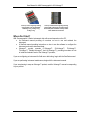
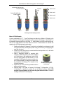
UV•Xchange™ User Manual UV•Xchange™ Quad Stack Version 1.57 19 SEPT 2014 UV•Xchange™ Single Stack Revision History Revision Date Description Author 1.1 8 November 2013 Document created. Dustin Olender 1.2 19 December 2013 ADDED COMMANDS, MATERIALS LIST, OP. DESCRIPTION Chris Bueley 1.3 9 January 2014 Updated images. Chris Bueley 1.4 14 January 2014 Formatting edits. Jehan Zouak 1.5 22-January-2014 Updated config. table Chris Bueley 1.55 28 January 2014 Formatting edits Jehan Zouak 1.56 20 February 2014 Updated operating mode description Chris Bueley 1.57 19 September 2014 28 April 2015 Updated technical drawing Jehan Zouak Added new GLS codes Jehan Zouak 1.58 User Manual for AML Oceanographic’s UV•Xchange™ Table of Contents General Description ....................................................................................................................2 Where Do I Start? .......................................................................................................................3 Shipping and Receiving ..............................................................................................................4 Receiving the Product .............................................................................................................4 Returning a Product to the Factory .........................................................................................4 Using the Product........................................................................................................................4 Safety .....................................................................................................................................4 Pressure Ratings ....................................................................................................................5 Common UV•Xchange™ Configurations ................................................................................5 Adding/Removing the Quartz Tube .........................................................................................5 Adding/Removing LED Modules .............................................................................................6 Metrec•X P1S4 Example: ..................................................................................................7 Installing the Product ..............................................................................................................8 Angular Alignment of LED Modules ........................................................................................8 Metrec•X P1S4 Example: ..................................................................................................9 Removing the Product ............................................................................................................9 Duty Cycle Selection and Specification.................................................................................10 What should the duty cycle be? ......................................................................................10 How is the duty cycle specified? .....................................................................................10 General Device Operation ....................................................................................................12 For use on logging instruments: ......................................................................................12 For use with Micro•X: ......................................................................................................13 UV Bulb Life ..........................................................................................................................14 Resetting the Bulb Life Counter ......................................................................................15 Pre-Deployment Procedures.................................................................................................16 Post-Deployment Procedures ...............................................................................................16 Maintaining the Product ............................................................................................................17 Periodic Maintenance ...........................................................................................................17 Inspecting and Replacing the O-rings ...................................................................................17 Communications .......................................................................................................................19 UV•Xchange™ Commands...................................................................................................19 UV•Xchange Command List .................................................................................................19 Technical Specifications ............................................................................................................20 LED Module Emission Pattern, Irradiance and Dosage ............................................................21 Support .....................................................................................................................................22 Troubleshooting ....................................................................................................................22 Frequently Asked Questions .................................................................................................22 Contact AML Oceanographic ................................................................................................23 Ordering Codes .........................................................................................................................24 Warranty ...................................................................................................................................25 Technical Overview Drawings ...................................................................................................26 1 User Manual for AML Oceanographic’s UV•Xchange™ General Description AML Oceanographic’s UV•Xchange™ is a modular anti-fouling system designed to protect sensors during long deployments. It uses ultraviolet light to prevent algae and other microorganisms from growing on sensor surfaces. By preventing initial colonization, the surface remains clear of larger, later-stage organisms, such as barnacles and seagrass. UV•Xchange™ can be swapped between any UV•Xchange™ enabled instruments, allowing one unit to be used to protect all of your X•Series instruments. Ultraviolet light is emitted by individual modules containing an LED. When moving the UV•Xchange™ between instruments, the quartz tube can be removed allowing access to the modules. Unscrewing the setscrew on the modules leaves them free to move along the rod, allowing them to be reconfigured to accommodate a multitude of sensor combinations: modules can be removed or added; modules are free to rotate beyond 360°; side-facing modules are reversible, allowing different pitch angles; rod height can be adjusted by adding or removing rods (from a one module stack up to a four module stack); The stems are distinguishable by their engraving, which include an 800000 series serial number. The LED modules are also distinguishable by their engraving, which denote an 850000 series serial number, optical power, and the LED’s angle from horizontal, known as the “pitch.” Up-Facing Module (78o module) Side-Facing Modules (13o module) Terminating Rod Central Rods Stem Red UV Warning Indicator Embedded Electronics Secondary Xchange Exploded view of UV•Xchange - Quad Stack™. Note: Quartz tube not shown. Two types of quartz tube are currently available for UV•Xchange™: a long version capable of supporting a four LED module stack, and a short version, capable of supporting a single LED module. A complete list of accessories can be found in Accessory Order Codes section of this manual. 2 User Manual for AML Oceanographic’s UV•Xchange™ Close-up of stem engraving showing serial number. From top to bottom: stabilizing o-ring, sealing o-ring, locking o-ring. Close-up of LED module engraving showing serial number, pitch angle and optical power. Downward pitch orientation is clearly visible. Note: Quartz tube not shown. Where Do I Start? AML Oceanographic X-Series instruments ship with several manuals on the CD: An instrument manual providing an overview on how to use and maintain the instrument; A SeaCast manual providing instructions on how to use the software to configure the instrument and review instrument data; Xchange™ product manuals (C•Xchange™, SV•Xchange™, P•Xchange™, T•Xchange™, Turbidity•Xchange™, and UV•Xchange™) providing overviews on how to install and maintain each of the Xchange™ products; If you are configuring an instrument for field use or lab testing, begin with the SeaCast manual. If you are performing instrument maintenance, begin with the instrument manual. If you are planning to swap an Xchange™ product, read the Xchange™ manual corresponding to your product. 3 User Manual for AML Oceanographic’s UV•Xchange™ Shipping and Receiving Receiving the Product When receiving a new UV•Xchange™ anti-fouling device, perform the following steps to ensure the product will be ready for deployment when required: Insure the glass tube is securely and completely installed on UV•Xchange. The glass tube should be sitting on the polycarbonate washer. Inspect the shipping container, looking for signs of damage. Damage to the shipping container could indicate damage to the product inside. Inspect for damage o Check the housing for cracks or bends o Check the internal components for damage o Check the connector for corrosion, dirt, and salt deposits Connect UV•Xchange to an instrument, ensuring it is installed tightly onto its mount. The blue locking sleeve should be tight and sitting less than 1mm from the instrument end cap. Connect the instrument to a computer using the data cable. Launch SeaCast and verify that the instrument tab is displaying accurate UV•Xchange™ information. The product’s serial number should be displayed. Returning a Product to the Factory If shipping for repair, obtain an RMA number from the service centre. Pack the product in its original shipping box to prevent damage during shipping. An RMA number can be requested using the contact options given in the Support section on page 21 of this manual. Using the Product Safety This product produces UVC radiation, which can cause damage to eyes and skin. A red warning light on the stem of UV•Xchange™ alerts the user that modules are powered and currently emitting UV light. When working near UV light the following precautions are recommended: Wear UV-resistant safety glasses If user will be exposed to UV light for a prolonged period of time (over 1 minute), wear long sleeves and a UV resistant face shield to protect skin Place shields around the UV light source to limit the area of exposure 4 Arrow shows UV Warning Indicator User Manual for AML Oceanographic’s UV•Xchange™ In general, above precautions are only necessary when UV•Xchange™ is powered out of water where light will travel much farther. Best practice is to install and align UV•Xchange™ while the instrument is off, as outlined in the Installing the Product section of this manual. Pressure Ratings Both UV•Xchange - Single Stack™ and UV•Xchange - Quad Stack™ are rated to operate to a maximum depth of 500 m. However, the instrument the product is used on will likely be depth limited by both its pressure case and sensors. Any deployment should never exceed the lowest (shallowest) of these pressure ratings. Common UV•Xchange™ Configurations UV•Xchange is typically shipped from the factory pre-configured for an instrument so there is no need for customer assembly. It is generally preferred that UV•Xchange not be disassembled unless required. However, in some circumstances customer configuration may be necessary. This section provides details on setup and configuration. UV•Xchange™ is supported in any secondary port on UV-enabled X•Series instruments, but the most common configurations are shown in the table below. To read the chart, start in the far left column by choosing your instrument, then move right, choosing your endcap type and desired sensor combination. Note the suggested position of your UV•Xchange™, the type and number of modules and their recommended pitch. Instrument Micro•X Sensor Parameter UV•X standalone Endcap Type Endcap Diagram Sensor Position P0S1 - S1 P1 CT or CP Smart•X S1 P1S2 S1 SVT or SVP Metrec•X / Plus•X CTD, CTD&Tu, SVTP, SVTP&Tu S2 P1 P1S4 S2 S2 P1 S1 S2 S3 S4 Sensor Type UV•X Single or Quad Stack C•Xchange UV•X Single Stack T•X or P•X SV•X UV•X Quad Stack T•X or P•X T•X or P•X C•X Tu•X P•X UV•X Quad Stack Stack Level 1 Stack Level 2 Stack Level 3 All Module types and stack configurations +78° 3mW -13° .5mW +13° .5mW -13° .5mW -13° .5mW -13° .5mW -13° .5mW T•Xchange Adding/Removing the Quartz Tube The glass tube may be removed (and subsequently re-installed) to allow access to the LED modules contained within. The glass tube should never be removed or installed while UV•Xchange is installed on an instrument endcap. Remember to clean and dry UV•Xchange™ prior to removing the quartz tube. The tube should only be removed in a clean, dry environment. To remove the quartz tube in its uninstalled state (when UV•Xchange is not installed in an instrument), grip the stem with one hand, and the quartz tube in another, and gently pull apart. The quartz tube is held in position with a locking o-ring whose groove is shared between the quartz tube and the stem. Once the resistance of 5 Stack Level 4 +78° 3mW User Manual for AML Oceanographic’s UV•Xchange™ the locking o-ring is overcome, the quartz tube should advance freely. Storing the quartz tube in its protective case is recommended. In the reverse manner, the quartz tube can be slid back over the modules and gently forced over the locking o-ring. The glass tube should never be installed on UV•Xchange while it is installed on an instrument endcap. Doing so will compress air and create an ‘air spring’ effect which will prevent the tube from being securely fastened. Always install the tube with UV•Xchange NOT installed on an instrument endcap. Before installing the quartz tube, ensure that the tube itself is free of cracks and chips. The polycarbonate washer acts as a bearing surface for the tube while pressurized, so it must also be flat and free of debris. Trapping debris between the quartz tube and the seat may result in failure of the quartz tube under pressure. Adding/Removing LED Modules UV•Xchange™ allows for the addition or removal of LED modules so that different numbers of sensors can be protected. General rules of operation are described: There will always be the same number of rods as modules, with a terminating rod in the final stack level. To remove only the uppermost rod, it is necessary to grip the flat with a wrench on the rod below it. Use a 5/32 hex to screw rod into position. Modules can be fixed in position by setscrew. Loosening the setscrew allows them to slide freely along the central rod, or rotate freely around the central rod. Once aligned, tighten the bottom module first, and then those at higher stack levels next. To adjust a module, you will need to loosen its setscrew and the setscrew of all modules above it. Side-facing modules are reversible, that is, they have contact pads on both sides. This allows for two different pitch orientations of the LED. Never attempt to rotate an LED module without first loosening the set screw. 6 User Manual for AML Oceanographic’s UV•Xchange™ Terminating Rod (5/32 Hex) PN: MTL-M0469 Setscrew (#8) Stack Level 4 Stack Level 3 Central Rod (5/32 Hex) PN: MTL-M0465 Stack Level 2 Stack Level 1 Step 1 Step 2 Step 3 Step 4 UV•Xchange module assembly procedure. Metrec•X P1S4 Example: A sensor combination of C, T, P, and Tu•Xchange are desired on a Metrec•X. Refering to the table in Common UV•Xchange™ Configurations, this requires UV•Xchange - Quad Stack™ to be installed in endcap position S3 with three 13° .5mW modules in the first three stack levels, and one 78° 3mW module in the fourth stack level. All 13° .5mW modules are oriented with negative pitch (LED facing down towards stem). 1. Starting with a blank UV•Xchange™ stem that is not installed in an instrument, install a single central rod by screwing into position using a 5/32 hex key, while gripping the stem with free hand. 2. Screw two more central rods into second and third stack position and, in the fourth stack position, a terminating rod. 3. Slide a side-facing module in negative pitch orientation (LED facing down) down the completed rod. Push down on the module and, using a 9/64 hex key, lightly tighten the #8 setscrew. It is not necessary to fully tighten the setscrew at this point, as it will be necessary to realign the modules once 13° module in negative pitch the assembled UV•Xchange™ is installed in the orientation (LED facing down X•Series instrument. towards stem). 4. Repeat for two more side-facing modules and then add an up-facing module. 5. Referring back to the table in Common UV•Xchange™ Configurations, in P1S4, UV•Xchange™ is installed in position S3 on the Metrec•X endcap. If the LED modules require alignment, do not install the glass tube at this time. Proceed to Installing the Product on the next page. 7 User Manual for AML Oceanographic’s UV•Xchange™ UV•Xchange Quad Stack™ with fully aligned modules in Metrec•X P1S4 configuration with cage removed for clarity. Note orientation of LED modules. Installing the Product 1. Ensure the instrument is off, either by inserting the black shorting plug or removing external power. 2. Refer to table in Common UV•Xchange™ Configurations to find suggested position for UV•Xchange™ with your sensor combination. 3. Ensure that the instrument port is clean and dry. 4. Check the connector’s O-ring for cleanliness (see below, Inspecting and Replacing the O-Rings). 5. If LED modules need alignment, remove quartz tube prior to installation of UV•Xchange™ in the instrument endcap. If no alignment is necessary, then the tube must be installed prior to installing UV•Xchange into the instrument. See Adding/Removing the Quartz Tube. 6. Align the connector to the sensor mount. 7. Place the connector into the mount. 8. Rotate the connector until it drops down into the mount enough to allow the blue locking sleeve threads to engage the mount threads. 9. Screw down the blue collar until it stops. The bottom of the knurled portion should be within 1 mm of the instrument end cap. 10. If LED modules need angular alignment, see Angular Alignment of LED Modules. Angular Alignment of LED Modules The LED modules can be rotated freely so that LEDs can be aligned to any angle. General rules for module alignment are listed below: Modules can be rotated freely once the setscrew has been sufficiently loosened on the module of interest, and on all those modules at higher stack levels. Alignment is best performed with all sensors removed from the endcap and the stem installed in the correct position. Module alignment can be performed by eye, by pointing the LED at the center of the empty sensor port. Because the LED beam pattern is broad, greater than 70° when in 8 User Manual for AML Oceanographic’s UV•Xchange™ water, alignment does not have to be exact. See LED Module Emission Pattern and Irradiance later in this manual for more details. Always push down on a module while tightening the setscrew. When tightening multiple modules, always start with the bottom or lowest stack level, and then work up. Metrec•X P1S4 Example: 1. It is best to perform alignment of the modules with all sensors and cage removed from the endcap and the UV•Xchange™ installed in the correct position. 2. The quartz tube must be removed to gain access to the LED modules. See Adding/Removing the Quartz Tube. 3. Loosen the setscrews in each of the LED modules. 4. Rotate the LED modules so that each is facing the center of the desired sensor port. Refer back to the table in Common UV•Xchange™ Configurations for details: o the module in stack level 1 is pointed towards S2, o the module in stack level 2 is pointed towards S4, o the module in stack level 3 is pointed towards S1, o the module in stack level 4 is pointed towards P1. 5. Push down on the top LED module while tightening the setscrew in the lowest module. 6. Tighten the remaining setscrews in each of the LED modules. 7. Now that all LED modules are aligned, remove UV•Xchange from the instrument. 8. Check the quartz tube o-rings for cleanliness. See Inspecting and Replacing the ORings 9. Slide the quartz tube over the LED modules and press onto the stem. The quartz tube should click into position as it passes the locking o-ring. The polycarbonate washer must be between the quartz tube and the housing. 10. Install UV•Xchange into the sensor endcap. 11. Install the sensors in the endcap. Removing the Product If the product has been used in salt water, rinse it in fresh water. Dry the product before removal to protect the connector. Unscrew the blue locking sleeve. Lift the product out of the mount. Ensure that the instrument socket is dry and clean, using compressed air if necessary. Immediately insert the blanking plug or a replacement Xchange™ product in the open socket. 9 User Manual for AML Oceanographic’s UV•Xchange™ T•Xchange™, P•Xchange™, Turbidity•Xchange™ and UV•Xchange™ Blanking Plug Duty Cycle Selection and Specification What should the duty cycle be? Selecting the correct duty cycle is key to optimizing the effectiveness of the product while minimizing power consumption. High duty cycles (ie. 50% or greater) provide more bio-fouling protection for deployments in environments with aggressive fouling, but with a penalty in power consumption. Alternatively, less aggressive fouling environments may warrant a reduced duty cycle to reduce power consumption. It is not possible to recommend one duty cycle that is appropriate for all deployments due the wide array of factors such as available power, aggressiveness of fouling in the environment, water turbidity, seasonal variation, depth, etc. With these factors in mind, AML Oceanographic generally recommends a duty cycle of 50%, consisting of 20 minutes on, 20 minutes off. This duty cycle has been shown to be effective in aggressive biofouling environments: tropical locations, shallow depth, high insolation deployments, etc. Increasing or decreasing the duty cycle may be appropriate however, based on the discretion of the user. How is the duty cycle specified? Duty cycle parameters are stored in the memory of the UV•Xchange system. This means that after specifying duty cycle, the programmed UV•Xchange system will operate at the same duty cycle even if installed on another instrument. The UV duty cycle operates independently from the scanning frequency of the sensors. There are two methods of specifying duty cycle: 1) using SeaCast, and 2) using command line. Method 1 is the most straightforward and is therefore recommended for most users. Refer to the SeaCast Manual for details. Method 2 is detailed below. If multiple UV•Xchange’s are installed on an instrument, it is possible to assign different duty cycles using the command line. To program duty cycle on a UV•Xchange system using a command line, commands must be issued directly to the controlling board in TALK mode. To this end, the controlling board must first be identified. This is done by issuing a DETECT command at the prompt. A typical example is as follows (issued commands shown in bold): >Minos.X Version 4.15.01 SN:30157 AML Oceanographic Ltd. 968.5 MBytes installed Beta 4 >DETECT Detecting Sensors 1: SV-C.Xchange SV.X SN 203087 04/10/13 SN: 05253 2: empty 3: P-T-TU-DO-UV.Xchange P.X SN 300310 03/04/13 UV.X SN 800007 01 01 SN: 65535 Detection complete 10 User Manual for AML Oceanographic’s UV•Xchange™ In this example, the instrument response indicates that UV•Xchange system (serial 800007) is controlled by controlling board 3. The two numbers following the serial number indicate that the currently programmed duty cycle is 1 minute on and 1 minute off, respectively. The next step is to go into TALK mode for that board. It should be noted that the UV•Xchange system may temporarily operate when entering TALK mode. Continuing the example: >TALK 3 Entering talk mode 3 > The controlling board may have multiple channels. The correct channel must be active to ensure the commands are sent to the UV•Xchange system. Channel assignments must first be identified using the following command: DISPLAY OPTIONS In this example: (output abridged for clarity) >display options … [Channel 1] SensorName1=P.Xchange Slot1=1 BoardSN1=065535 SensorSN1=300310 CalDate1=03/04/13 CalBy1=MT~ CalRange1=0-100 dbar CalAccuracy1=0.011 %FS PA=-1.240512E+01 PB= 0.000000E-01 PC= 0.000000E-01 PD= 0.000000E-01 PE= 1.919974E-03 PF= 0.000000E-01 PG= 0.000000E-01 PH= 0.000000E-01 PI=-4.221045E-10 PJ= 0.000000E-01 PK= 0.000000E-01 PL= 0.000000E-01 PM= 4.019435E-15 PN= 0.000000E-01 PO= 0.000000E-01 PP= 0.000000E-01 [Channel 2] SensorName2=UV.Xchange Slot2=2 BoardSN2=065535 SensorSN2=800007 UVOnTime=1 UVOffTime=1 UVBulbLife=12 UVBoardLife=131 11 User Manual for AML Oceanographic’s UV•Xchange™ > In this example, UV•Xchange is present on channel 2 and a P•Xchange sensor is present on channel 1. To ensure commands are sent to the correct channel, the following command is used: SET ACTIVE x where ‘x’ is an integer corresponding to the channel. In this instance, ‘x’ should be set to 2. In cases of multiple UV•Xchange modules installed on an instrument, separate duty cycles for each UV•Xchange can be specified by switching between active channels. To adjust duty cycles, the following commands are used: SET BIOFOULING ONTIME x SET BIOFOULING OFFTIME x where ‘x’ is an integer value in minutes. In this example, the objective is to configure the UV•Xchange system to operate for 10 minutes on and 20 minutes off. Note that sending a break command (CTRL + C) exits talk mode. Alternatively, power cycling the instrument will also take it out of talk mode. >SET BIOFOULING ONTIME 10 On time set to 10 minutes >SET BIOFOULING OFFTIME 20 Off time set to 20 minutes > Exiting talk mode > The instrument response to the two commands confirms that the desired duty cycle is specified. Duty cycle timing may also be confirmed be re-issuing a DISPLAY OPTIONS command. General Device Operation For use on logging instruments: (Applicable to all instruments excluding Micro•X) There are two configurations which govern how the UV•Xchange system operates on logging instruments. One setup is to have the instrument activate the UV duty cycle (as per the programmed duty cycle selection) only when the instrument is logging or in MONITOR mode. This is referred to as MODE 2 configuration. In this setup, the instrument will not cycle the UV system if the instrument remains at prompt. This configuration may be thought of as a ‘benchtop mode’ as it allows an instrument to be powered and functional without UV•Xchange operating. In this mode, instrument settings may be altered and cast data may be downloaded without operating the UV system. An instrument may also be deployed in this configuration if the instrument is actively logging or in monitor mode for the duration of the deployment. To specify this configuration, the command is: SET BIOFOULING PWROFF 12 User Manual for AML Oceanographic’s UV•Xchange™ When an instrument is ready for deployment in this configuration, the typical deployment workflow is: 1. The instrument is put into logging or MONITOR mode via command or insertion of red arming plug. Refer to the instrument specific manual for details. 2. The UV system will begin to cycle. This will be indicated by the red indicator ring of the UV•Xchange system. The alternative configuration is referred to as MODE 1 configuration. In this instance, the UV system will cycle as per its programmed duty cycle at all times regardless of instrument state. This means that the UV system will operate even if the instrument is not actively logging or in MONITOR mode. This configuration may be thought of as a general deployment mode. This configuration is suitable for users who intend to deploy an instrument with or with without the instrument continuously logging or in MONITOR mode, such as event-driven scans, third party loggers, etc. As the UV system will be active at all times, care should be taken when configuring sensors or setting up the instrument prior to deployment. To specify this configuration, the command is: SET BIOFOULING PWRON When an instrument is ready for deployment in this configuration, the typical deployment workflow is: 1. The instrument is activated, either by inserting a connector cable or applying external power. 2. A carriage return is sent to the instrument, which instructs the instrument to prompt.* 3. The instrument is primed by issuing a DETECT command, instructing the instrument to identify all installed Xchange sensors. The instrument will then return to a prompt.* 4. The UV•Xchange system will begin cycling as per the programmed duty cycle. UV operation will be indicated by the red indicator ring. *These steps may not be required if the instrument is set to autobaud or to output data on power-up. Refer to the instrument manual for details. When in the MODE 1 (PWRON) configuration, the instrument will also begin to cycle the UV with the insertion of a red arming plug, similar to the MODE 2 (PWROFF) configuration. For use with Micro•X: When installed on a Micro•X, UV•Xchange operates in a manner analogous to MODE 1 configuration. This means that the UV duty cycle will operate at all times (after initialization) regardless of state. In some situations, the user may prefer to have UV•Xchange begin to cycle immediately on power-up without initializing the instrument. This can be achieved by specifying a fixed baud rate on the instrument using the command: SET DETECT 0 b where ‘b’ is an integer corresponding to baud rate, given as: 13 User Manual for AML Oceanographic’s UV•Xchange™ ‘b’ Value: 1 2 3 4 5 6 7 8 Baud Rate 600 1200 2400 4800 9600 19200 38400 57600 In this configuration, the UV will begin to cycle immediately on instrument power-up. UV Bulb Life UV•Xchange includes a built-in timer that records total cumulative on-time for a given LED module stack. This is done to provide the user with an indication of remaining LED life. UV•Xchange assumes that all LED modules are installed or removed together so they have the same cumulative on-time. Removing or adding additional LED modules without resetting the timer will result in incorrect times. For this reason, all modules should be replaced as a set. The specified life of the UV LEDs is such that they diminish to 50% of their original power after 5,000 hours of total cumulative operation time. It should be noted that the LEDs will still operate at this time and that the reduction in intensity may be compensated for by increasing the duty cycle of UV•Xchange. It is recommended that the LED modules be replaced after 5,000 hours of operation. Refer to Ordering Codes for ordering information. The most straightforward method of determining cumulative on-time is to use SeaCast. Refer to the SeaCast manual for details. It is also possible to determine total on-time from the command line, using the procedure below. After entering TALK mode with the appropriate board (refer to the Duty Cycle Selection section or instrument manual), enter the following command: DISPLAY OPTIONS A typical response is as follows: >display options [Instrument] Type=P-T-TU-DO-UV.Xchange SN=065535 Firmware=1.06 plus UV beta 5 SampleUnits=continuous SampleInterval=0 DisplayHeader=yes StartupMode=Prompt DetectionMode=a5 RX=on TrailingSpace=off PressureFormat=42 TemperatureFormat=23 TurbidityFormat=42 14 User Manual for AML Oceanographic’s UV•Xchange™ DoxygenFormat=21 StartupRawReal=Real PressureUnits=dbar TemperatureUnits=Celcius TurbidityUnits=NTU DoxygenUnits=mg/L Latitude=+45.000 PressureOffset=+0.000 UsePressureOffset=no AddressMode=off AddressByte=09 SerialParity=none SerialEcho=on CommunicationsDelay=0 NMEAMode=off AutoMonitorSeconds=0 [Channel 1] SensorName1=P.Xchange Slot1=1 BoardSN1=065535 SensorSN1=300310 CalDate1=03/04/13 CalBy1=MT~ CalRange1=0-100 dbar CalAccuracy1=0.011 %FS PA=-1.240512E+01 PB= 0.000000E-01 PC= 0.000000E-01 PD= 0.000000E-01 PE= 1.919974E-03 PF= 0.000000E-01 PG= 0.000000E-01 PH= 0.000000E-01 PI=-4.221045E-10 PJ= 0.000000E-01 PK= 0.000000E-01 PL= 0.000000E-01 PM= 4.019435E-15 PN= 0.000000E-01 PO= 0.000000E-01 PP= 0.000000E-01 [Channel 2] SensorName2=UV.Xchange Slot2=2 BoardSN2=065535 SensorSN2=800007 UVOnTime=10 UVOffTime=20 UVBulbLife=116 UVBoardLife=116 > From the instrument response, it is evident that the total cumulative on-time for the installed UV module stack is 116 minutes. Resetting the Bulb Life Counter The bulb life counter must be reset when a new stack of LED modules is installed into UV•Xchange. The most straightforward method to reset the bulb life counter is through SeaCast. Refer to the SeaCast manual for details. 15 User Manual for AML Oceanographic’s UV•Xchange™ Alternatively, the bulb life counter may be reset from the command line. This is done by entering into TALK mode with the appropriate controlling board (refer to instrument manual for details) and issuing the following command: SET BIOFOULING RESETBULBLIFE Pre-Deployment Procedures Upon Receipt o Use the Shipping and Receiving instructions to verify the condition of the instrument. Before in-situ deployment o Ensure the UV light is properly mounted on the instrument. The blue locking sleeve should be fully threaded onto a secondary sensor port on the instrument, sitting less than 1mm from the instrument end cap. o Ensure the LED modules are properly oriented and aligned to protect each sensor. o Ensure the correct duty cycle has been set. o Test the instrument to ensure the product is functioning as expected. Post-Deployment Procedures Ensure the product is clean and dry before storage. 16 User Manual for AML Oceanographic’s UV•Xchange™ Maintaining the Product Periodic Maintenance Periodic maintenance will prolong the life of the UV•Xchange™. The following steps are recommended: If the housing is dirty or oily, allow it to soak in warm, soapy water before cleaning with a rag or soft brush. When finished, rinse with fresh water to remove any residual soap or dirt. Before each use: o Before installing on an instrument, check the O-ring under the blue locking sleeve and under the housing of the product for silicon grease. o Ensure that the housing is clean and undamaged. o Check the quartz tube for cracks or chips. Replace tube if any defects are found. o Check the polycarbonate seat for debris or deformation. Replace as necessary. o Ensure that the product is properly installed on the instrument After each deployment: o Clean and rinse the product using fresh water. o Dry the product completely, and store it in a cool, dry place. Long term storage preparation o Ensure the instrument has been thoroughly cleaned and dried. o Remove all Xchange products from the instrument and dry the connectors. o Lubricate the instrument and Xchange product connector contacts with a silicone spray. o Lubricate the retainer rings and O-rings with silicone grease. o Install connector and blanking plugs in the instrument. Inspecting and Replacing the O-rings It is crucial to keep the UV•Xchange™ product’s O-rings clean and greased. Any fibres or dirt on the O-rings will allow water into the connector or into the housing. To gain access to the Orings, perform the following steps: Remove the sensor from the instrument, then remove the housing tube from the stem. Check the O-rings on the connector and on the stem. The O-rings should be slick with grease. If they are dry, apply silicone grease. Inspect the O-rings for dirt. Clean and reapply grease, if necessary Inspect the O-rings for nicks and cracks. If any are found, the O-rings must be replaced. Apply silicone grease to the new O-rings before using them. Use the following O-ring sizes: o 2-015-N70D Buna Nitrile O-rings for the connector O-rings. o 2-015-N70D Buna Nitrile O-rings for the connector O-rings. o 2-017-70D EPDM O-rings for the sealing and stabilizing o-rings. o AS568-114 N40D Buna Nitrile for the locking o-ring. Caution: Do not use a sharp instrument to remove the O-rings. If the O-ring grooves are scratched, the O-rings will not provide a waterproof seal. The O-rings can be removed easily with bare hands as shown below. 17 User Manual for AML Oceanographic’s UV•Xchange™ O-rings O-ring Removal 18 User Manual for AML Oceanographic’s UV•Xchange™ Communications UV•Xchange™ Commands When using SeaCast, the full instrument command set is not usually necessary. However, the operator can issue text commands to the instrument as well as to specific sensors on an instrument. This can be done from SeaCast or any terminal emulation program such as HyperTerminal. There is additional functionality on UV•Xchange™ equipped instruments with respect to the command set. To use these commands, direct communication with the UV•Xchange™ sensor must be established. There are two ways to accomplish direct communication with the UV•Xchange™ sensor. 1. On a Micro•X instrument with the UV•Xchange™ option, the UV•Xchange™ commands can be given directly to the instrument by typing the commands into the terminal emulation program. 2. On all other X-Series instruments, the TALK command is used to direct communications to the UV•Xchange™ sensor. Use the following procedure to accomplish this: Entering TALK Mode o Establish communications with the instrument. o Send the DETECT command to the instrument. The instrument will return a list of sensors detected on each slot of the instrument. The UV•Xchange™ is usually in the primary slot, but on instruments equipped with a C•Xchange™ sensor, the UV•Xchange™ may be located in a different slot. o Send the TALK 1 command to the instrument. Replace the “1” in the command with the appropriate slot number if required. This command directs subsequent communications directly to the sensor board. Exiting TALK Mode o Press the CTRL and C keys simultaneously. UV•Xchange Command List Command Description SET BIOFOULING PWRON Configures UV system to operate as per duty cycle regardless of instrument state. ie: UV system will operate even when instrument is at prompt. MODE 1 in SeaCast. SET BIOFOULING PWROFF Configures UV system to operate as per duty cycle only when instrument is in MONITOR mode or logging. MODE 2 in SeaCast. SET BIOFOULING ONTIME x * Specifies the on time for the UV system, where ‘x’ is an integer in minutes. 19 User Manual for AML Oceanographic’s UV•Xchange™ SET BIOFOULING OFFTIME x * Specifies the off time for the UV system, where ‘x’ is an integer in minutes. SET BIOFOULING RESETBULBLIFE * Resets the running on-time counter for the LED module stack. *These commands must be issued to the controlling board. On all logging instruments, this is achieved by entering TALK mode to the appropriate board. Refer to the instrument manual for more details. TALK mode is not required on a Micro•X instrument. For the full set of commands, please refer to the Commands section of the instrument manual. Technical Specifications LED Modules Side Facing Upward Facing (0.5 mW optical power) (3 mW optical power) 120o 70o 30 mA - 5 to +55 oC 120o 70o 80 mA -5 to +55 oC Single Module Multi Module Viewing Angle (in air) Viewing Angle (in water) Current Draw Operating Temperature Range Housings 22 mA Fused quartz Titanium 500 m 1.02” Current Draw (Stem only) Tube Material Stem Material Depth Rating Diameter Length 3.80” 20 5.54” User Manual for AML Oceanographic’s UV•Xchange™ LED Module Emission Pattern, Irradiance and Dosage The following plot shows the irradiance field of a 13° .5mW LED module oriented with negative pitch in sea water at 0 NTU. A minimum irradiance of 10 µW/cm2 at 20 minute on/20 minute off duty cycle is recommended to keep a target surface clear of biofouling. This minimum irradiance threshold is highlighted in red in the figure below, which requires the target surface to be within approximately 7 cm (2.75 in.) for effective biofouling control. Larger throw distances are achievable with higher optical powers, such as the 3mW and 5mW modules. This plot presents a side view of the beam, but the top view is similar, as pattern is relatively axisymmetric. Contact AML Oceanographic Ltd. to discuss optimal settings for your application. Irradiance field of a 13° .5mW LED module oriented with negative pitch in sea water at 0 NTU. View is from the side. 21 User Manual for AML Oceanographic’s UV•Xchange™ Support Troubleshooting Instrument fails to detect the product: Is the product properly mounted on the instrument? Check the connector on both the UV•Xchange™ and the instrument for corrosion or damaged contacts. Cycle the instrument power. LEDs fail to turn on: Are the LED modules in contact with one another? Try loosening the set screws on the LED modules, pushing down on the module stack, and retightening the set screws. For more details see Changing LED Module Orientations. SeaCast fails to recognize the product: Be sure to download the latest version of SeaCast. Frequently Asked Questions Can LED modules be stacked upside down? Yes. The 13o modules are designed to operate in either orientation (LED facing up or down). This allows the system to accommodate a wide range of configurations. Can you stack just three modules in a multi-module housing? There is no minimum number of LED modules that must be present. It is acceptable to have anywhere from 1 to 4 modules in a multi-module quartz housing, in any orientation. The general rule is ‘if it fits, it will work.’ How can I tell if my LED modules are working? It is not possible to directly observe the UV light as it is beyond the visual range of the human eye. However, ordinary white paper such as the paper found in a given notebook or what this manual is printed on will fluoresce under UV light. Holding a strip of white paper in front of an LED module will indicate if the LED is working as the paper will fluoresce a deep blue. Note that caution should be exercised so as not to irradiate exposed skin. How long will my LED modules last? The rated life of the LEDs is 5,000 hours of total cumulative on-time. This means that the LEDs will lose 50% of their original intensity at their rated life. The LEDs will still operate beyond rated life and the reduction in intensity can be compensated for by increasing duty cycle. 22 User Manual for AML Oceanographic’s UV•Xchange™ Contact AML Oceanographic Service To request an RMA or technical support Email: [email protected] Phone: 1-250-656-0771 Phone : 1-800-663-8721 (NA) Fax: 1-250-655-3655 Sales For all general sales inquiries Email: [email protected] Phone: 1-250-656-0771 Phone : 1-800-663-8721 (NA) Fax: 1-250-655-3655 Website http://www.AMLoceanographic.com Customer Portal My AML Oceanographic is AML's online data centre. This secure area within our website is designed to offer one easy location for interested individuals and organizations - distributors, customers, prospects, and other members of our community - to manage their interactions with AML. My AML Oceanographic will allow you to: View and manage your assets (instruments and sensors) Consult instrument diagnostic summaries View and download calibration and conformity certificates View and manage your technical support cases Consult and download sales estimates, sales orders, and invoice copies View account balances and generate account statements Assess inventory availability at AML To access the Customer Portal, please navigate to the Support button - located on the top right of the AML Oceanographic home page - select Customer Centre from the options on the drop down menu and follow the instructions provided. Mailing and Shipping Address AML Oceanographic 2071 Malaview Ave. Sidney, BC, Canada V8L 5X6 23 User Manual for AML Oceanographic’s UV•Xchange™ Ordering Codes Complete UV•Xchange Systems AML Part No. Description B: blank module L: horizontal (+/-13o) module V: vertical (+78o) module XCH-UV-V XCH-UV-BBBV XCH-UV-LLLV UV•Xchange, Short, 1 Vertical LED UV•Xchange, Long, 1 Vertical LED & 3 Blanks UV•Xchange, Long, 1 Vertical & 3 Horizontal LEDs Components AML Part No. Optical Power (mW) Angle from Horizontal, or Pitch (degrees) Reversible Rotatable SUB-G0714 .5 +/-13 Yes Yes SUB-G0713 3 +78 No Yes SUB-G0725 Blank --- Yes Yes MTL-M0469 Central Rod – terminating section MTL-M0465 Central Rod – non terminating section GLS-0032 GLS-0035 GLS-0036 GLS-0031 Glass tube – 1 module length Glass tube – 2 module length Glass tube – 3 module length Glass tube – 4 module length 24 Image User Manual for AML Oceanographic’s UV•Xchange™ Warranty AML Oceanographic warrants the instrument for a period of two years from the date of delivery. AML will repair or replace, at its option and at no charge, components which are found to be defective. The warranty applies only to the original purchaser of the instruments. The warranty does not apply if the instrument has been damaged, by accident or misuse, and is void if repairs or modifications are made by any other than authorized personnel. This warranty is the only warranty given by AML. No warranties implied by law, including but not limited to the implied warranties of merchantability and fitness for a particular purpose shall apply. In no event will AML be liable for any direct, indirect, consequential, or incidental damages resulting from any defects or failure of performance of any instrument supplied by AML. 25 User Manual for AML Oceanographic’s UV•Xchange™ Technical Overview Drawings 26 THE INFORMATION CONTAINED IN THIS DRAWING IS THE SOLE PROPERTY OF AML OCEANOGRAPHIC LTD. ANY REPRODUCTION IN PART OR WHOLE WITHOUT THE WRITTEN PERMISSION OF AML OCEANOGRAPHIC LTD IS PROHIBITED REVISION TABLE REV DESCRIPTION DATE BY SV Xchange 31.8 1.25 87.1 3.43 C Xchange Right Angle 44.5 1.75 108.4 4.27 62.7 2.47 FLOW DIRECTION C Xchange Straight 44.5 1.75 131.1 5.16 FLOW DIRECTION 57.3 2.26 36.1 1.42 ALTERNATE FLOW DIRECTION P Xchange 48.8 1.92 11.4 R.45 72.5 2.86 ENDCAP FACE LEVEL WHEN INSTALLED ON INSTRUMENT OR BULKHEAD. T Xchange 65.5 2.58 11.4 R.45 89.5 3.53 ENDCAP FACE LEVEL WHEN INSTALLED ON INSTRUMENT OR BULKHEAD. TITLE: Xchange Sensor / Device Overview DRAWN 2071 Malaview Avenue W., Sidney B.C. Canada V8L 5X6 (250) 656 0771 Fax: (250) 655 3655 TOLERANCES: ANGLES: FRACTIONS: HOLE SIZES: 0.00: 0.000: 1 1/32 0.005(0.13) 0.015(0.38) 0.005(0.13) UNLESS OTHERWISE SPECIFIED: ORIGINAL SCALE:1:1 DATE I.L. 3rd ANGLE PROJECTION REV SNS-GA-03351-A 26FEB2010 DIM'S ARE IN INCHES (MM) SURFACE FINISH: 63 DRAWING NO.: SIZE B MATERIAL: N/A SLD FILE NO.: N/A AML NO. N/A SHEET NO. Sheet1 of 2 THE INFORMATION CONTAINED IN THIS DRAWING IS THE SOLE PROPERTY OF AML OCEANOGRAPHIC LTD. ANY REPRODUCTION IN PART OR WHOLE WITHOUT THE WRITTEN PERMISSION OF AML OCEANOGRAPHIC LTD IS PROHIBITED REVISION TABLE REV DESCRIPTION BY DATE A ADDED TUX AND UVX DO 25MAR2014 Tu Xchange 28.7 1.13 133.3 5.25 109.6 4.31 ENDCAP FACE LEVEL WHEN INSTALLED ON INSTRUMENT OR BULKHEAD. UV Xchange 140.3 5.52 25.8 1.02 117.0 4.61 ENDCAP FACE LEVEL WHEN INSTALLED ON INSTRUMENT OR BULKHEAD. 25.8 1.02 96.6 3.80 72.8 2.87 ENDCAP FACE LEVEL WHEN INSTALLED ON INSTRUMENT OR BULKHEAD. TITLE: Xchange Sensor / Device Overview DRAWN 2071 Malaview Avenue W., Sidney B.C. Canada V8L 5X6 (250) 656 0771 Fax: (250) 655 3655 TOLERANCES: ANGLES: FRACTIONS: HOLE SIZES: 0.00: 0.000: 1 1/32 0.005(0.13) 0.015(0.38) 0.005(0.13) UNLESS OTHERWISE SPECIFIED: ORIGINAL SCALE:1:1 DATE I.L. 3rd ANGLE PROJECTION REV SNS-GA-03351-A 26FEB2010 DIM'S ARE IN INCHES (MM) SURFACE FINISH: 63 DRAWING NO.: SIZE B MATERIAL: N/A SLD FILE NO.: N/A AML NO. N/A SHEET NO. Sheet2 of 2