1
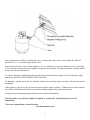
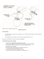
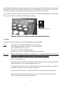
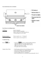
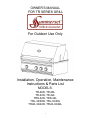
OWNER’S MANUAL FOR TR SERIES GRILL For Outdoor Use Only Installation, Operation, Maintenance Instructions & Parts List MODELS: TR-26N, TR-26L TR-32N, TR-32L TRS-32N, TRS-32L TRL-32/38N, TRL-32/38L TRLD-32/44N, TRLD-32/44L 1 Contents Page For Your Safety Safety Rules Gas Barbecue Specifications Gas Connection LP Tank Requirement Installation Location Clearances Electrical Lighting Instructions Operation Cleaning and Maintenance Parts Removal and Replacement Trouble Shooting Wire Diagram TR-26/TR-32/TRL-32/TRS-32/TRL-38 Parts Identification TR-26/TR-32/TRL-32/TRS-32/TRL-38 Exploded View TRLD-32/44 Parts Identification TRLD-32/44 Exploded View Do’s & Don’ts 3 6 7 8 9 10 11 12 13 14 15 16 17 18 19/20 21 22 23 24 Message to the Proud Owner of this Quality Gas Grill Congratulations on the purchase of the high quality, high performance grill. Read this manual carefully to understand all the instructions about how to install, operate and maintain for optimum performance and longevity. Keep this manual in a safe place for future reference. For any assistance, contact us. Make sure to provide the Model Number and Serial Number of the grill. Thank you for buying our grill. We wish you years of cooking pleasure. 2 For Your Safety READ THESE SAFETY INSTRUCTIONS PROPANE MODELS: WARNING Correct LP Gas Tank Use LP gas grill models are designed for use with a standard 20 lb. Liquid Propane Gas (LP gas) tank, not included with grill box. Never connect your gas grill to an LP gas tank that exceeds this capacity. A tank of approximately 12 inches in diameter by 181/2 inches high is the maximum size LP gas tank to use. A Propane tank with an OPD (Overfill Prevention Device) must be used. This safety feature prevents the tank from being over-filled which can cause malfunction of the LP gas tank, regulator and/or grill. The LP gas tank must be constructed and marked in accordance with specifications of the U.S. Dpt. of Transportation (DOT). In Canada, the LP gas tank must meet the Canadian Transportation and Communications (CTC) specifications. Also be sure to read and follow all LP instructions on the following page. If the outdoor cooking gas appliance is not in use, the gas must be turned off at the supply cylinder. (a) Do not store a spare LP-gas cylinder under or near this appliance; (b) Never fill the cylinder beyond 80 percent full; and (c) If the information in (a) and (b) is not followed exactly, a fire causing death or serious injury may occur. 1. The LP gas tank has a shutoff valve, terminating in an LP gas supply tank valve outlet, that is compatible with a Type 1 tank connection device. The LP gas tank must also have a safety relief device that has a direct communication with the vapor space of the tank. 2. The tank supply system must be arranged for vapor withdrawal. 3. The LP gas tank used must have a collar to protect the tank valve. Never connect an unregulated LP gas tank to your gas grill. The gas regulator assembly supplied with your gas grill is adjusted to have an outlet pressure of 11" water column (W.C.) for connection to an LP gas tank. Only use the regulator and hose assembly supplied with your gas grill. Replacement regulators and hose assemblies must be those specified by manufacture. Fuels used in gas or oil-fired appliances and the products of combustion of such fuels, contain chemicals known to the State of California to cause cancer, birth defects and/ or other reproductive harm. This warning is issued pursuant to California Health & Safety Code Sec. 25249.6. WARNING Failure to comply with these instructions could result in a fire or explosion that could cause serious bodily injury, death, or property damage. WARNING Your grill will get very hot. Never lean over the cooking area while using your grill. Do not touch cooking surfaces, grill housing, grill lid or any other grill parts while the grill is in operation, or until the grill has cooled down after use. Failure to comply with these instructions may result in serious bodily injury. Grill lnstallation Codes This gas grill must be installed in accordance with all local codes. In areas without local codes, follow the latest edition of the National Fuel Gas Code ANSI Z223.1. In Canada, installation must conform to standard CAN/CGA 1b149.1 or 1-b149. 2 (Installation Code for Gas Burning Appliances and Equipment) and all local codes. Proper Placement and Clearance of Grill Never use your gas grill in a garage, porch, shed, breeze way or any other enclosed area. Your gas grill is to be used outdoors only, at least 24 inches from the back and 18 inches to the side of any combustible surface. Exceptions would include usage with approved vent hoods and all proper materials and clearances according to local codes. Your gas grill should not be placed under any surface that will burn. Do not obstruct the flow of ventilation air around the gas grill housing. This outdoor gas grill is not intended to be installed in or on recreational vehicles and/or boats. 3 Have your LP gas tank filled by a reputable propane gas dealer and visually inspected and requalified at each filling. Never fill the gas tank beyond 80% full. Have your propane gas dealer check the release valve after every filling to ensure that it remains free of defects. Always keep LP gas tanks in an upright position. Do not store (or use) gasoline or other flammable vapors and liquids in the vicinity of this gas grill. An LP gas tank that is not connected for use must NOT be stored on bottom shelf or in the vicinity of this or any other gas grill. Do not subject the LP gas tank to excessive heat. Never store an LP gas tank indoors. If you store yourgas grill in the garage or other indoor location, always disconnect the LP gas tank first and store it safely outside and out of reach of children. LP gas tanks must be stored outdoors in a wellventilated area. Disconnected LP gas tanks must not be stored in a building, garage or any other enclosed area. When your gas grill is not in use the gas must be turned off at the LP gas tank. The regulator and hose assembly must be inspected before each use of the grill. If there is excessive abrasion or wear or if the hose is cut, it must be replaced prior to the grill being used again. Keep the gas regulator hose away from hot grill surfaces and dripping grease. Avoid unnecessary twisting of hose. Visually inspect hose prior to each use for cuts, cracks, excessive wear or other damage. If the hose appears damaged do not use the gas grill. A strong gas smell, or the hissing sound of gas indicates a serious problem with your gas grill or the LP gas tank. Failure to immediately follow the steps listed below could result in a fire or explosion that could cause serious bodily injury, death, or property damage. Shut off gas supply to the grill. Turn the Control Knobs to the OFF position. Open grill lid. Get away from the LP gas tank. Do not try to fix the problem yourself.. If odor continues or you have a fire you cannot extinguish, call your fire department. Do not call near the LP gas tank because your telephone is an electrical device and could create a spark resulting in fire and/or explosion. NOTE: The normal flow of gas through the regulator and hose assembly can create a humming noise. A low volume of noise is perfectly normal and will not interfere with operation of the grill. If humming noise is loud and excessive you may need to purge air from the gas line or reset the regulator excess gas flow device. This purging procedure should be done every time a new LP gas tank is connected to your grill. For help call the Customer Service Helpline for assistance. Built-in Units Utilizing Natural Gas When connecting a built-in unit to the natural gas supply in your home, please ensure the pipe joint compound is resistant to the action of natural gas. In addition, please observe the following: The barbecue and its individual shut-off valve must be disconnected from the gas supply piping system during any pressure testing of that system at test pressures in excess of ½ psi (3.5 kPa). The barbecue must be isolated from the gas supply piping system by closing its individual manual shutoff valve during any pressure testing of the gas supply piping system at test pressures equal to or less than ½ psi (3.5 kPa) The units are supplied from the factory equipped for Never light your gas grill with the lid closed or before checking to insure the burner tubes are fully seated over the gas valve orifices. Never allow children to operate your grill. Do not allow children to play near your grill. WARNING 4 use with natural gas and includes a natural gas regulator. If operation with propane gas is desired, you must purchase a Propane Model. In addition, a Propane Gas Regulator MUST be installed in the gas supply line from the propane gas tank. Please remember to check all gas connections for leaks after the piping is completed. Follow the procedure under the heading "CAUTION: LEAK CHECKING." WARNING Read the “Lighting Instructions” in this manual, before lighting this appliance. For Your Safety 1. Do Not store or use gasoline or other flammable vapors and liquids in the vicinity of this or any other appliance. 2. An LP cylinder not connected for use shall not be stored in the vicinity of this or any other appliance. � CAUTION: BEWARE OF FLASHBACK CAUTION: Spiders and small insects occasionally spin webs or make nests in the grill burner tubes during transit and warehousing. These webs can lead to a gas flow obstruction which could result in a fire in and around the burner tubes. This type of fire is known as a ”FLASHBACK” and can cause serious damage to your grill and create an unsafe operating condition for the user. Although an obstructed burner tube is not the only cause of ”FLASHBACK”, it is the most common cause. To reduce the chance of ”FLASHBACK”, you must clean the burner tubes before assembling your grill, and at least once a month in late summer or early fall when spiders are most active. Also perform this burner tube cleaning procedure if your grill has not been used for an extended period of time. TESTED IN ACCORDANCE WITH ANSI STANDARD FOR OUTDOOR COOKING GAS APPLIANCES. THIS GRILL IS FOR OUTDOOR USE ONLY. Check your local building codes for the proper method of installation. In the absence of local codes, this unit should be installed in accordance with the National Fuel Gas Code No. Z223.1CAN/CGA – B149.1, natural gas installation code or CAN/CGA – B149.2, propane installation code. CALIFORNIA PROPOSITION 65WARNING If you smell gas: 1. Shut off gas to the appliance. 2. Extinguish any open flames. 3. Open lid. 4. If odor continues, immediately call your gas supplier. The Burning of gas cooking fuel generates some by-products which are on the list of substances which are known by the State of California to cause cancer or reproductive harm. California law requires businesses to warn customers of potential exposure to such substances. To minimize exposure to these substances, always operate this unit according to the use and care manual, ensuring you provide good ventilation when cooking with gas. 5 not be stored in or around the grill in the cabinet or in the masonry enclosure. Portions of the grill can be extremely hot while in use and can cause severe burns. 8. Protect your hand with a glove or mitt when opening and operating the grill. Open grill lid slowly to allow heat and smoke to escape before fully opening. Safety Rules 1. It is important to follow these rules to avoid fire hazard, property damage or bodily injury from improper installation or usage of the grill. For safety, READ all rules carefully and check local codes. 9. Never use aluminum foil to line the crumb pan or grill racks. This can alter airflow for proper combustion and also build up heat in the control area causing the knobs and igniters to melt. 2. It is prohibited to install the grill in recreational vehicles/mobile homes, trailers, boats, etc. The grill is for outdoor installation and use only. 10. Grease is highly flammable. Allow hot grease to cool down before attempting to handle it. Clean grease tray often so that grease does not accumulate and stay in it. 3. Ensure proper installation by following the installation instructions. Make sure to know where the gas supply shut-off valve is located. It should be readily and easily accessible. 11. Do not use the grill in a windy area. 12. Do not obstruct the flow of air into the front of the grill. 4. Check all gas line joints or connection for gas leak with soap water solution. Never check gas leak with an open flame. Gas Connections Check gas type - use only the type of gas indicated in the rating plate. 5. Do not attempt to repair or replace any part of the grill unless specifically recommended in this manual. All other services should be performed by a qualified service technician. Do Not connect an unregulated gas line to the appliance. Safe and satisfactory operation depends to a great extent on the proper installation of the appliance. The installation must comply with the local codes, or in the absence of local codes, with either the National Fuel Gas Code, ANSI Z223.1 or CAN/CGA – B149.1 or 149.2. 6. Do not place clothing or other flammable material on or near the appliance. Do not wear loose-fitting clothes or long sleeves while using the grill as some fabrics can be highly flammable. Installer supplied manual gas shut-off valve must be installed in an easily accessible location in the gas supply line ahead of the pressure regulator (4” W.C.) which is also to be provided by the installer. 7. Children should be carefully supervised when they are in the vicinity of the grill. Do not allow them to get close while in use. Items of interest to children should 6 The outdoor cooking gas appliance and its individual shut-off valve must be disconnected from the gas supply piping system during any pressure testing of the system at test pressures in excess of ½ Psi (3.5 kPa). The outdoor cooking gas appliance must be isolated from the gas supply piping system by closing its individual manual shut-off valve during any pressure testing of the gas supply piping system at test pressures equal to or less than ½ Psi (3.5 kPa). The supply line must be sized and installed to provide a sufficient supply of gas to meet the maximum demand of the grill without undue loss of pressure. The sealant used on the threaded joints of the gas pipe must be a type resistant to the action of LP gases. GAS BARBECUE SPECIFICATIONS BURNER INPUT RATING: TR-26/TR-32/TRS-32/TRL-32/TRL-38: Grill Main Burner Rotisserie TRLD-32/44: Grill Main Burner Rotisserie Rotisserie Natural Gas Connection: 18,000 BTU / each 15,000 BTU 20,000 BTU / each 12,500 BTU 15,000 BTU (Installer to Provide Regulator) Appliance pressure 5” W.C. Inlet pressure 5” - 14” W.C. Check with your local gas utility company or with local codes before installing gas lines. Assemble pipe fittings as shown. Apply pipe compound on male joints only. Install regulator with the proper orientation for the gas flow. 7 LP Gas Connection Appliance pressure Inlet pressure 10” W.C. 11” – 14” W.C. Purchase a standard 20 lbs. LP tank with QCC – 1 fitting. Assemble pipe/hose assembly as shown. 8 After completion of assembly, turn the tank valve on and turn the control valves on the grill to the ‘HI/IGN’ position for 10 – 15 seconds to purge the line of air. Inspect the hose before each use of the appliance. If it is evident there is excessive abrasion or wear, or the hose is cut, it must be replaced prior to the appliance being put into operation. The replacement hose assembly shall be that specified by the manufacturer. To connect, insert the regulator inlet into the tank valve and turn the black coupler clockwise until the coupler tightens up. DO NOT OVER TIGHTEN THE COUPLER. To disconnect, turn the tank valve off. Hold the coupler sleeve and turn counter clockwise. The inlet line will be disengaged. If the appliance is not in use, the gas must be turned off at the supply cylinder. Cylinder must be stored outdoors out of reach of children and must not be stored in a building, garage or any other enclosed area. A dented, rusty or damaged propane cylinder must be replaced immediately. Check for leaks every time the cylinder is replaced or reconnected. All leaks must be corrected immediately. *Never use an open flame to check for leaks. (See illustration on p.13) 9 LP Tank Requirements: The L.P. gas cylinder must be constructed and marked in accordance with the specifications for L.P. gas cylinders of the U.S. Department of Transportation (DOT) and designed for use with a QCC-1 quick disconnect system only. The cylinder must be provided with a shut-off valve terminating in an L.P. gas supply cylinder valve outlet specified, as applicable, for connection No. QCC-1. The cylinder must be provided with a listed overfilling prevention device. The pressure regulator and hose assembly supplied with the outdoor cooking gas appliance must be used. Replacement of pressure regulators and hose assemblies can be purchased from authorized dealers. The cylinder supply system must be arranged for vapor withdrawal. Make sure the LP cylinder has a collar to protect the cylinder valve. (a) Do not store a spare LP gas cylinder under or near this appliance. (b) Never fill the cylinder beyond 80 percent full. (c) If the information in (a) and (b) are not strictly followed, a death-causing fire or serious injury may occur. 10 Installation Location For All Models NOTE: When installing a barbecue equipped for liquid propane in an island, it must be crossventilated in accordance with the current standard. NEVER store extra propane tanks next to the one in use. Only one propane tank is permitted underneath the grill at any given time. NOTE: When using Propane, EXTREME CAUTION should be used to provide ample ventilation of vapor from the enclosure. LP Gas vapor is heavier than air and SERIOUS INJURY from a DANGEROUS EXPLOSION could occur if LP Gas is allowed to accumulate in an enclosure and then ignited. Both the Barbecue enclosure and LP cylinder enclosure require venting that must be provided at the floor level of the enclosure to allow any leaking LP Gas vapor to escape. Upper & lower ground level vents (20 sq. in. minimum each) MUST BE PROVIDED on both sides of built-in construction. Please ask local dealer for full details. NOTE: Upper & lower ground-level vents (20 sq. in. minimum each) MUST BE PROVIDED for combustion air on both sides of built-in construction. Please ask local dealer for full details. Barbecues must be installed in accordance with CSA specifications and all local building codes. Choose a location where the flow of air on the front of the grill is not obstructed. Due to high temperatures, place the grill out of traffic and keep away from clothing, furniture, etc. Keep the gas line connection as short as possible. Do not install in recreational vehicles/mobile homes, trailers, boats, etc . 11 Clearances Combustible Construction Minimum horizontal clearance from sides and back of the unit to adjacent vertical combustible construction extending above top of unit, 6 inches from side and 15 inches from back. Do not locate under overhead unprotected combustible construction. Non-Combustible Construction Sides of the grill can be 0” from non-combustible wall, below the cooking surface. Built-in Installation For non-combustible masonry enclosure installation, follow the cut out dimensions as shown. Non-combustible Construction Model TR-26 TR-32 TR-38 TRLD-32 TRLD-44 W 24 ½” 30 ½” 38 ½” 33 ¼” 45 ¼” D 20 ¾” 20 ¾” 20 ¾” 20” 20” 12 H 10” 10” 10” 11” 11” The bottom of the grill must be supported on both sides and back or full width with opening as shown for gas connection. Electrical Electrical outlet for Rotisserie motor must be installed to the left side of the grill. The outdoor cooking gas appliance, when installed, must be electrically grounded in accordance with local codes or, in the absence of local codes, with the National Electrical Code, ANSI/NFPA 70, or the Canadian Electrical Code, CSA C22.1. Keep any electrical supply cord and fuel supply hose away from any heated surface. BRIQUETTES: Place briquettes burner cover above each burner. Leak Testing All gas piping and connections must be tested for leaks after installation or service. All leaks must be corrected immediately. Open the valve (shut-off or ‘ON’ LP tank). Test for leaks by applying liquid soap solution to all joints. Bubbles forming indicate gas leak. NEVER USE AN OPEN FLAME TO CHECK FOR LEAKS. 13 TRLD-44 is not available with Flash Tube Lighting Instructions Before Lighting: Check gas line/hose for signs of wear, abrasion or cuts. If evidence of deterioration is visible, replace the part prior to use. If you smell gas, check for leaks. If odor continues, immediately call for service. Keep your face and body away from the grill top when lighting. Grill and Rotisserie Burner Lighting 1. Open lid before lighting. Make sure all knobs are in the ‘OFF’ position. (REMOVE WARMING RACK BEFORE USING ROTISSERIE) 2. Push and turn burner knob slowly to ‘HI’ position, a clicking will occur. 3. Repeat step 2 until unit lights. 4. If the burner does not ignite within 4 seconds, turn the gas off, wait for 5 minutes and then repeat steps 1 and 3. 5. For complete shut down, turn all knobs to the ‘OFF’ position. For LP, also turn the cylinder valve off when not in use. 14 If grill or Rotisserie burners do not light with igniter, they can be lit manually. For Main burners, turn knob on far right burner to high. Place match or lighter at the top of the flash tube on right side of basin. Once lit turn next burner on adjacent to far right burner, when lit repeat for far left burner on 32” model. On rear burner use long Bic lighter or hearth match, turn rear burner to high and hold long match or Bic hearth lighter to burner surface. Back burner should light immediately. Light at top of flash tube *Models TRLD-32 & 44 do not offer the flash tube option Operation DO NOT LEAVE YOUR GRILL UNATTENDED WHILE IN OPERATION. Grill: Grill burners are controlled individually with a control knob. After lighting, turn the knob to HI, LO or in between as desired. Turn on as many burners as required. The top cover may be closed during grilling. Keep the top cover in the closed position during the pre-heat period. Rotisserie: Remove Warming rack before turning on rear rotisserie burner! Not doing so will result in damage and will not be covered under warranty! Turn the control knobs to HI. Plug in the motor power cord to a properly grounded receptacle. Rotisserie cooking can be done with grill burners as well as with the Rotisserie burner ‘ON’. The skewer slides in from the side with the tip sliding into the motor shaft adapter. The slot on the handle side should be on the side support panel edge. Use the prongs to hold the meat. Tighten thumbscrew on the prong hubs to secure in place. When ready, turn the switch on the motor box to the ‘ON’ position. The skewer will rotate slowly. Stop the motor before removing the skewer. 15 Cleaning and Maintenance Cleaning: Your Bar-B-Q grill works better and lasts longer if properly cleaned and maintained. Clean the grill immediately after every use. Turn grill off before starting to clean. Protect your hand with a good mitt when cleaning the hot grill. Use a wire brush, dip in water and scrub the grill to soften and loosen food spills. The food spills will fall into the crumb pan. Do not use Aerosol cleaners on hot grill surface. Chemicals may produce noxious fumes and may ignite on contact with the hot surface. Shield: Burner shields (Briquette holder) are made up of stainless steel. After every use, allow the shields to cool down. Remove and soak in water with a mild soap or detergent. Replace when dry along with the briquettes. Grease Pan: Empty grease pan as required to prevent overflowing. After use, remove the grease pan and brush off the contents. Clean with hot water and soap or detergent. All stainless steel parts should be cleaned with a mild soap or detergent or with a liquid cleanser especially made for stainless steel. Never attempt to clean stainless steel with steel wool, abrasive clothes or powders. Maintenance Keep outdoor cooking gas appliance area clear and free from combustible materials, gasoline and other flammable vapors and liquids. Do not obstruct the flow of combustion and air ventilation. Keep the ventilation opening(s) of the cylinder enclosure free and clear from debris. Visually check burner flames. There are many different stainless steel cleaners available. Always use the mildest cleaning procedure first, scrubbing in the direction of the grain. To touch up noticeable scratches in the stainless steel, sand very lightly with dry 100 grit emery paper in the direction of the grain. Specks of grease can gather on the surfaces of the stainless steel and bake on to the surface and give the appearance of rust. For removal use, an abrasive pad (Scotch Brite is good) in conjunction with a stainless steel cleaner. Always rub in the direction of the grain. Never scrub the stainless steel with steel wool. Steel particles left on the stainless steel will soon rust and give the appearance that the parts are rusting. The burners, control area, crumb pan, etc. should be kept clean at all times. During prolonged non-use of the grill, spiders and insects can nest in areas that will adversely affect the functioning of the grill. Check burner inlets, orifice hood (gas inlet to burner), igniter, sparkers, etc. thoroughly and clean before use. 16 Front Panel Removal for All Models Parts Removal and Replacement Grill Burner: - Remove top grates. - Remove briquettes and shields - Remove clip at rear of burner and slide out. - Clean and replace in reverse order. Rotisserie Sparker: - Remove sparker cover – lift and pull. - Remove sparker screws and pull out. Trouble Shooting Problem Burner will not light Solution - Check gas supply to burner by manually lighting the burners. - Check pilot side of valve for spark while gas is off - Make sure spark area is clean from debris, webs etc. - Make sure you now have a spark - If no spark, check valve for defects Improper burner flame - Check burner gas inlet area for any blockage and clear. Check orifice hoods for any clogging and clean. Check pressure if flame is too low or too high. Check gas supply tank (LP) if running low. Make sure that knobs are in off position when turning tank valve on! 17 TRLD- 4 LEDS 32 TRLD- 5 LEDS 44 2 LIGHTS 2 LIGHTS 18 TR-26/TR-32/TRL-32/TRS-32/TRL-38 Parts List ITEM PART# 7 8 9 10 TR001 TR002 TR003 TR004 TR005 TR006 TR007 TR008 TR009 TR010 TR011 TR012 TR013 TR014 TR015 TR016 11 TR017 12 TR018 TR019 TR020 TR021 TR022 TR023 TR024 TR025 TR026 TR027 TR028 TR029 TR030 TR031 TR032 TR033 TR034 TR035 TR036 TR037 TR038 TR039 TR040 TR041 TR042 TR043 TR044 TR045 1 2 3 4 5 6 13 14 15 16 17 18 19 20 21 22 23 24 25 26 QTY. DESCRIPTION TR-26 26”-TOP HOOD 32”-TOP HOOD 38”-TOP HOOD IGNITOR BRACKET-I.R.BURNER IGNITOR-I.R.BURNER IGNITOR WIRE(1400mm) -I.R.BURNER IGNITOR WIRE(1600mm) -I.R.BURNER I.R.BURNER 26”-REAR HOOD 32”-REAR HOOD (TR-32、TRL-32) 32”-REAR HOOD (TRS-32) 38”-REAR HOOD LIGHT BOX (LEFT) LIGHT (LEFT) LIGHT BOX (RIGHT) LIGHT (RIGHT) ORIFICE(LPφ1.05) -I.R.BURNER ORIFICE(NGφ1.6) -I.R.BURNER ORIFICE ELBOW 26”-WARMING RACK 32”-WARMING RACK 38”-WARMING RACK 26”-TOP GRATE 32”-TOP GRATE 38”-TOP GRATE 26” -BURNER COVER 38” -BURNER COVER “U” BURNER 26 “-INNER BASIN 32 “-INNER BASIN 38 “-INNER BASIN 26 “-CRUMB TRAY 32 “-CRUMB TRAY 38 “-CRUMB TRAY 26 “-BASIN FRAME 32 “-BASIN FRAME 38 “-BASIN FRAME 26 “-GREASE TRAY 32 “-GREASE TRAY 38 “-GREASE TRAY TRANSFORMER 20W TRANSFORMER INLET CORD TERMIINAL BLOCK LP REGULATOU LP FLARE FITTING REGULATOU BRACKET 19 TR-32 TRL-32 TRS-32 1 1 1 1 1 1 1 1 1 1 1 1 1 TRL-38 1 1 1 1 1 1 1 1 1 1 1 1 1 1 1 1 1 1 1 1 1 1 1 1 1 1 1 1 1 2 3 3 3 2 3 3 3 2 1 3 3 3 1 1 1 4 4 4 1 1 1 1 1 1 1 1 1 1 1 1 1 1 1 1 1 1 1 1 1 1 1 1 1 1 1 1 1 1 1 1 1 1 1 1 1 ITEM PART# 27 28 29 TR046 TR047 TR048 TR049 TR050 TR051 TR052 TR053 TR054 TR055 TR056 TR057 TR058 TR059 TR060 TR061 TR062 TR063 TR064 TR065 TR066 TR067 TR068 TR069 TR070 TR071 TR072 TR073 TR074 TR075 TR076 TR077 TR078 TR079 TR080 TR081 TR082 TR083 TR084 TR085 TR086 TR087 TR088 TR089 30 31 32 33 34 35 36 37 38 39 40 41 42 43 44 45 46 47 48 49 50 51 52 53 54 55 56 57 QTY. DESCRIPTION NG REGULATOU NG FLARE FITTING FLEX TUBE 500mm 26 “-MANIFOLD PIPE 32 “-MANIFOLD PIPE 38 “-MANIFOLD PIPE VALVE SEAL RING GAS VALVE-I.R.BURNER GAS VALVE(LPφ1.3)- “U”BURNER GAS VALVE(NGφ1.93)- “U”BURNER FLEX TUBE-I.R.BURNER 980mm FLEX TUBE-I.R.BURNER 1050mm BEZEL CONTROL KNOB LOGO PLATE LIGHT SWITCH-ON/OFF 32 “-LIGHT WIRE 38 “-LIGHT WIRE 26 “-CONTROL PANEL 32 “-CONTROL PANEL (TR-32) 32 “-CONTROL PANEL (TRL-32) 32 “-CONTROL PANEL (TRS-32) 38 “-CONTROL PANEL 32 “ LED WITH WIRE 38 “ LED WITH WIRE LED MODULE HOLDER LED MODULE SIDE BURNER LED OUTLET BRACKET-MOTOR MOTOR-ROTISSERIE HANDLE-ROTISSERIE SPIT COLLOR-ROTISSERIE SCREW-SKEWER FORK SKEWER FORK φ5 32 “-SKEWER ROD 38 “- SKEWER ROD 26 “-HOOD HANDLE TUBE 32“-HOOD HANDLE TUBE 38 “-HOOD HANDLE TUBE END CAP SPACER-HANDLE END CAP-HANDLE RUBBER STOPPER TEMPRATURE GAUGE TEMPRATURE GAUGE BEZEL TR-26 TR-32 TRL-32 TRS-32 TRL-38 1 2 1 1 1 2 1 1 2 1 1 2 1 1 2 1 1 1 1 4 1 3 3 1 4 1 3 3 1 3 2 2 2 2 2 1 4 4 1 2 1 3 3 1 1 5 5 1 2 1 1 1 1 1 1 1 1 1 1 1 3 2 1 1 1 1 1 1 1 1 1 3 2 1 1 1 1 1 1 1 1 1 1 1 1 3 2 1 1 1 2 2 2 1 1 Please see your local dealer for service and parts replacement 20 4 4 1 3 3 1 5 1 5 5 2 2 2 1 1 2 2 2 1 1 1 2 2 2 1 1 1 2 2 2 1 1 TRL-32/38 Exploded View 21 TRLD-32/44 Parts List ITEM PART# QTY. DESCRIPTION TRLD-32 TRLD-44 1 TRLD001 TOP HOOD 1 1 2 TRLD002 IGNITOR BRACKET-I.R.BURNER 1 1 3 TRLD003 IGNITOR-I.R.BURNER 1 1 4 TRLD004 WIRE(1700mm) -I.R.BURNER 1 1 5 TRLD005 I.R.BURNER 1 1 6 TRLD006 REAR HOOD 1 1 7 TRLD007 LIGHT BOX (LEFT) 1 1 8 TRLD008 LIGHT (LEFT) 1 1 9 TRLD009 LIGHT BOX (RIGHT) 1 1 10 TRLD010 LIGHT (RIGHT) 1 1 11 TRLD011 ORIFICE(LPφ1.05) -I.R.BURNER 1 1 ORIFICE(NGφ1.6) -I.R.BURNER 1 1 12 TRLD012 ORIFICE ELBOW 1 1 13 TRLD013 WARMING RACK 1 1 14a TRLD014 TOP GRATE- LARGE 0 5 14b TRLD015 TOP GRATE- SMALL 4 1 15 TRLD016 BURNER SEPARATOR 2 3 16 TRLD017 BURNER COVER 3 4 17 TRLD018 CAST BURNER 3 4 18 TRLD019 INNER BASIN 1 1 19 TRLD020 CRUMB TRAY 1 1 20 TRLD021 BASIN FRAME 1 1 21 TRLD022 GREASE TRAY 1 1 22 TRLD023 TRANSFORMER 20W 1 1 23 TRLD024 TRANSFORMER INLET CORD 1 1 24 TRLD025 TERMIINAL BLOCK 1 1 25 TRLD026 LP REGULATOR 1 1 26 TRLD027 LP FLARE FITTING 1 1 27 TRLD028 REGULATOR BRACKET 1 1 28 TRLD029 NG REGULATOU 1 1 29 TRLD030 NG FLARE FITTING 1 1 30 TRLD031 FLEX TUBE 500mm 1 1 31 TRLD032 MANIFOLD PIPE 1 1 22 32 TRLD033 VALVE LATCH 4 5 33 TRLD034 1 1 3 4 3 4 1 1 4 5 35 TRLD037 36 TRLD038 GAS VALVE-I.R.BURNER GAS VALVE(LPφ1.2)“U”BURNER GAS VALVE(NGφ1.85)“U”BURNER FLEX TUBE-I.R.BURNER 1050mm CONTROL KNOB 37 TRLD039 BEZEL 4 5 38 TRLD040 LOGO PLATE 1 1 39 TRLD041 CONTROL PANEL 1 1 40 TRLD042 LIGHT SWITCH 2 2 41 TRLD043 LIGHT WIRE 1 1 42 TRLD044 LED MODULE BRACKET 1 1 43 TRLD045 LED MODULE 1 1 44 TRLD046 SIDE BURNER LED OUTLET 1 1 45 TRLD047 LED LIGHT WIRE 1 1 46 TRLD048 BRACKET-MOTOR 1 1 47 TRLD049 MOTOR-ROTISSERIE 1 1 48 TRLD050 HANDLE-ROTISSERIE 1 1 49 TRLD051 SPIT COLLOR-ROTISSERIE 1 1 50 TRLD052 SCREW-SKWER FORK 3 3 51 TRLD053 SKWER FORK φ5.7 2 2 52 TRLD054 SKWER ROD 1 1 53 TRLD055 1 1 54 TRLD056 2 2 55 TRLD057 HOOD HANDLE END CAP SPACER SPACERHANDLE END CAP-HANDLE 2 2 56 TRLD058 RUBBER STOPPER 2 2 57 TRLD059 TEMPRATURE GAUGE 1 1 58 TRLD060 TEMPRATURE GAUGE BEZEL 1 1 TRLD035 34 TRLD036 Please see your local dealer for service and parts replacement 23 TRLD-32/44 Exploded View 24 DO'S & DON'TS DO.. DON'T.. � Install grill closer than 14" on the sides or 16" on the back to any combustible construction. � Attempt any adjustment of the regulator, it has been preset and tested. � Allow the LP tank to lie on its side. Keep in an upright position. � Use plastics or untempered glass utensils on the grill. � Attempt to move an aluminum foil pan while it is hot. Let it cool first before moving it. � Cover or block any air openings in the bottom of the grill with foil. � Wear long, loose flowing clothing around the grill. Long flowing hair is also easily ignited especially by unexpected flare-ups. Tie hair back or wear a hat or a scarf. � Put food on the grill and leave it unattended or unwatched for long periods. Most fats can catch fire even on the lower setting. � Clean Flame Tamers in any solution other than a boiling detergent water. Then rinse well, dry and reuse. � Use caustic materials, i.e., lye , to clean grill parts. � Store any additional Propane gas tanks under barbecue. When cooking with hood closed NEVER exceed temperatures of 480°F (250°C). � Have propane cylinder (LP units) filled by authorized LP supplier. � Record your grill model number on your instructions and keep the instructions and parts list in a convenient place. � Check all gas line connections for leaks with soapy solution prior to lighting, tighten until bubbles disappear. � Raise the hood before lighting the burner. � Preheat the grill 5 minutes maximum before cooking. � After cooking, turn the grill off, then take a long handled soft brass bristle brush and brush off the cooking grills. Then turn off gas at the Propane tank or main valve. � Use a mitt to turn off tank valve, it can get hot. � Cook with hood down when possible. It is generally faster and more efficient. Trapped smoke adds to the flavor. � Turn the gas off promptly should you be unable to light the grill immediately. Wait a full 5 minutes before attempting to light grill again. � Have proper tools, tongs, mittens and hot pads ready prior to removing foods. � Trim excess fats from meats to minimize flareups. � Let the grill cool before removing any parts for cleaning. � Be careful of the control valve setting. LP gas is hotter and the lower setting may be generally preferred. � Cover the barbecue when not in use. � Use a mitt or glove when opening BBQ lid or turning off Propane tank valve after use. 25