1
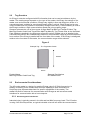
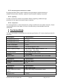
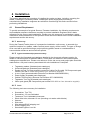
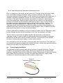
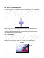
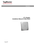
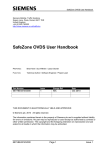
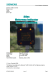
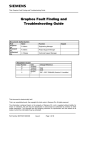
Siemens Mobility, Traffic Solutions
Sopers Lane, Poole, Dorset, BH17 7ER
United Kingdom
+44 (0)1202 782000
http://www.siemenstraffic.com/
Installation Commissioning and
Maintenance Handbook for the
Tagmaster
Selective Vehicle Detection System
© Siemens plc. 2015 All rights reserved.
The information contained herein is the property of Siemens plc and is supplied without liability
for errors or omissions. No part may be reproduced or used except as authorised by contract or
other written permission. The copyright and the foregoing restriction on reproduction and use
extend to all media in which the information may be embodied.
The names of products of third parties named in this document may be trademarks of their respective
owners.
Document Authorisation
Role
Name
Prepared by:
Stephen Thorpe
Reviewed by:
Mike Tonkin
Authorised by:
Colin Whipps
Document Record
Issue Number Date
001
Aug 2013
002
Mar 2015
Part Number 667-HE-46655-000
Function
Project Support
Engineer
Product Support
Manager
Technical Support
Manager
Signed
Comments/Revision Details
First Issue
Update part numbers
Issue 2
Page 1 of 24
Contents
1
1.1
Introduction................................................................................................................ 3
Purpose and scope.................................................................................................. 3
2
2.1
2.2
2.3
2.3.1
2.3.2
2.3.3
2.3.4
System Overview ...................................................................................................... 4
Reader Overview ...................................................................................................... 4
Tag Overview ........................................................................................................... 7
Environmental Considerations ............................................................................... 7
Electromagnetic Interference ..................................................................................... 7
Electromagnetic Interference in cables ...................................................................... 8
Lightning .................................................................................................................... 8
Temperature .............................................................................................................. 8
3
Technical Data........................................................................................................... 8
4
4.1
4.1.1
4.1.2
4.1.3
4.2
4.2.1
4.3
4.3.1
4.3.2
4.3.3
4.4
Installation ................................................................................................................. 10
General Requirement............................................................................................... 10
Site Survey ................................................................................................................ 10
Typical Installation Equipment Inventory .................................................................... 10
Tools ......................................................................................................................... 10
Mounting the Reader ............................................................................................... 11
Orientating the Reader............................................................................................... 12
Cable Installation ..................................................................................................... 12
Cable Installation General .......................................................................................... 12
Reader Cable Connections ........................................................................................ 13
Cable from Pole Top Termination to Remote Enclosure ............................................ 19
Power Supply Installation ....................................................................................... 19
5
5.1
5.2
5.3
5.4
5.5
Commissioning and System Verification .................................................................... 20
General requirements .............................................................................................. 20
Power Up and Voltage Check ................................................................................. 20
Programming reference tags .................................................................................. 20
Reader Orientation and alignment.......................................................................... 21
Tag Installation ........................................................................................................ 21
6
6.1
6.2
6.3
Maintenance .............................................................................................................. 22
General maintenance philosophy and introduction .............................................. 22
Annual Periodic Inspection..................................................................................... 22
Trouble Shooting..................................................................................................... 22
7
Contacts within Technical Support and Tagmaster ..................................................... 24
Part Number 667-HE-46655-000
Issue 2
Page 2 of 24
Related Documentation
Document Number
Title
667-DZ-46655-000.VSD Tagmaster Family Tree
667-LP-46655-000-ETC Tagmaster Illustrated Parts List
Installation and Commissioning Handbook - Installation
667-HE-20664-000
Testing (General)
667-PA-46655-000
Tagmaster Global Support Plan
667-HQ-46655-000
Tagmaster Quick Start Guide
667-SD- 46655-000
Tagmaster Test Specification
Doc no. 06-118 06
Tagmaster Gen 4 User Manual
1 Introduction
1.1
Purpose and scope
This handbook gives details on the Installation, Commissioning and Maintenance for the
Tagmaster Selective Vehicle Detector system. The handbook does not detail the interface or
connection details to a supervising computer system.
The Tagmaster product in composed of two constituent elements;
Reader
Tags
The make up and configurations of these two constituent elements is dependent upon the
system use. The configuration and make up is described in the appropriate section, according to
their relevance to associated activity.
This handbooks detail the following:
Basic overview of the Tagmaster hardware at module level, at a level necessary for
installation, commissioning and maintenance
Installation Procedure
Commissioning Procedure
Routine maintenance / inspection procedures
Tagmaster faults
Hardware configuration
An illustration of the reader and a listed breakdown of the reader, in particular the component
parts is provided in section 2.
Please note it is important to check the contents of the shipment for completeness and possible
damage. If the contents are damaged, report the circumstances immediately with the carrier and
the Tagmaster sales or service organization, contact details provide in section 6. Returns for
repair should be carried via the standard Siemens Mobility Traffic Solutions Returns Process.
Part Number 667-HE-46655-000
Issue 2
Page 3 of 24
2 System Overview
The two main elements of a Tagmaster identification system are the Reader and the
ID-tags. The system can be augmented by elements such as a host/controlling computer
system. The system is designed to control external devices, such as traffic lights and barriers.
Figure 1
The figure above shows the overview of a Tagmaster identification system with a pole mounted
Reader, an ID-tag mounted on the inside of a car windscreen, a host computer, a power supply
and a barrier.
2.1
Reader Overview
The LR-series Tagmaster readers are devices for reading ID-tags, using 2.45 GHz frequencies.
In addition to reading tags some readers also have the capability to write information to
tags. The reader has built-in antennas for communication with ID-tags, as well as various serial
interfaces for communication with a host computer.
The Tagmaster reader is the system’s primary component. The system is produced in Sweden
by Tagmaster. Tagmaster manufacture, configure and distribute a series of readers of varying
complexity. The two variant of Tagmaster reader provided for installation and subsequent
support by Siemens are:
Product Name
LR-6
LR-6 XL
Detection Range
10m
14m
Siemens Part Number
667/9/99400/010
667/9/99400/014
As indicated the primary difference between these two readers is the read range of the tags,
with a nominal range of 10 metres and 14 meters respectively.
Part Number 667-HE-46655-000
Issue 2
Page 4 of 24
The Readers are designed for above ground installation. In most instances the Reader will be
mounted to an existing, standard 4 metre traffic pole. However, a Universal Pole Mounting Kit
will allow fitting on poles between 70mm and 140mm diameter.
Power input and relay activation output signal can be made using a single 4 core cable, this
allows the use of a single cable entry to provide these functions. To allow updates and reader
diagnostics to be carried efficiently, following installation, it is advisable to provide a remote
connection to the Reader’s Ethernet port. An Ethernet cable can be run to a suitable enclosure,
where the associated Tagmaster power supply may also be housed. The reader is powered with
a voltage ranging from +10 to +30 V DC.
The LR-series reader is designed for configuration with a wide range of input and
output devices, including relays, isolated I/O, indicators, and a buzzer. The Reader has several
communication alternatives and is easily integrated using the following communication
interfaces:
Ethernet
RS232
RS485
USB Host
Wiegand/Mag-stripe
Micro SD memory card
Note: the Readers can be configured with varying levels of application software. The application
software loaded may not be designed to support the use of these interfaces, consult
corresponding software manual for further information.
Part Number 667-HE-46655-000
Issue 2
Page 5 of 24
Reader Components (please refer to figure 2)
1 Lid
2 Controller board
3 RF-unit
4 Externally-visible indicators
5 Tamper switches
6 Red system status indicator
7 Green system status indicator
8 Yellow system status indicator
9 TX-unit
10 Enclosure base
11 Chassis
12 Knock-out for cable entry
13 Terminal blocks
14 Ground screw
15 Ethernet connector with link state and activity indicators
16 Micro SD slot
17 USB host connector (intended for internal expansion)
18 Pressure balance membrane
Figure 2
Part Number 667-HE-46655-000
Issue 2
Page 6 of 24
2.2
Tag Overview
An ID-tag is a device configured with ID information that can be read at a distance by the
reader. The reading range depends on; the type of the reader, the ID-tag, the settings of the
reader, and environmental conditions. ID-tags vary slightly in size and shape but all are of a
compact designed, suitable for mounting discretely within a vehicle. Each ID-tag has its own
unique number and it is possible to read many ID-tags concurrently. A lithium battery is used in
the ID-tag to achieve a high communication speed and a long reading range.
Siemens advocate the use of three types of tags; MarkTag MaxType Tamper Evident Tag,
MarkTag Classic Credit Card Tag and the MarkTag Memory Tag. Please refer to the illustrated
Parts Catalogue detailed in the document reference section. Reader set-up is detailed in the
commissioning section but fundamentally maximum communication range is achieved when the
front surface of the ID-tag is parallel with the front side of the reader. If the ID-tag is misaligned,
relative to the front side of the reader, the communication range will be reduced.
Figure 3
Example Tag – The Tagmaster Classic
290mm
55mm
Product Name
MarkTag Classic Credit Card Tag
2.3
Siemens Part Number
667/9/99401/000
Environmental Considerations
The LR-series reader is a device for reading ID-tags using 2.45 GHz frequencies. In
addition to reading, some readers also have the capability to write information to
ScriptTags (see separate data sheet for specific capabilities of the reader). The
reader has built-in antennas for communication with ID-tags as well as various serial
Interfaces for communication with a host computer.
2.3.1 Electromagnetic Interference
Industrial noise is typically present in the kHz and low MHz frequency band. The LR series
is using 2.45 GHz frequencies, so typical industrial noise will not affect the communication.
Part Number 667-HE-46655-000
Issue 2
Page 7 of 24
2.3.2 Electromagnetic Interference in cables
By using specified cables, proper shielding, and grounding as well as selecting a
suitable communication interface, optimum communication reliability is ensured.
2.3.3 Lightning
In order to protect the reader from possible effects of lightning, additional surge
protection on the inputs and outputs may be required.
2.3.4 Temperature
For most applications, normal atmospheric cooling is sufficient for the reader. However, if heat
is generated close to the reader, the use of forced cooling or heat shields should be
considered.
3 Technical Data
The table immediately below details the technical specification, LR 3 series details provided for
reference.
Description
Specification
Reading Range (LR-6)
0–6m
Reading Range (LR-3)
0–5m
Power Supply
+10 to + 30 VDC
Power Consumption
4.5 W
Current Consumption
175/350 mA @ 24/12 VDC
Radio Frequency Range
CW: 2436. 1-2464.1 MHZ, Channel 5 – 97
FHSS*:2400 – 2483.5 Mhz
Tag Data Speed
Low 4 kbps and high 16 kbps
Ethernet
10/100 Mbps
Serial Output
RS232, 2 wire or 4 wire RS485. Up to 115.2 kbps
Description
Specification
Operating Temperature Range
-30o C to + 60oC
Sealing
IP 65
Description
Specification
Size (LR-6)
290 x 165 x 56 mm
Power Cable Entry Fitting
8 cable entry fitting holes diameter 16mm
(LR-6)
Weight (LR-6)
Part Number 667-HE-46655-000
0.95kg
Issue 2
Page 8 of 24
Material
Part Number 667-HE-46655-000
plastic
Issue 2
Page 9 of 24
4 Installation
This section describes the procedure of installing the reader and tags, including; mounting the
reader, installing the necessary cables, installing the power supply and performing a
commissioning. Installation engineers are advised to read through this entire section before
performing installations.
4.1
General Requirement
To provide an example of a typical Siemens Tamaster installation, the following requirements
and installation sequence has been compiled to provide Installation Engineers with a basic
reference for site surveys and installations. Please note, this sequence is provided as a guide,
modification and enhancement of this process will be carried out based on the actual installation
requirements and the site survey.
4.1.1 Site Survey
During the Presale/Tender phase of a prospective installation a site survey, to ascertain the
optimum locations for; readers, cable runs and power supply, will be carried. The type of ID-tags
to be used will be specified during a project planning phase, based on considerations of
communication distances and movement speeds.
4.1.2 Typical Installation Equipment Inventory
Please consult the illustrated part catalogue detailed in the document reference section for
details of individual parts as indicated below. Those parts not detailed in the illustrated parts
catalogue are detailed here. Please note reference to the site survey and project plan should be
made before a full parts inventory associated with site installations is compiled.
Tagmaster readers (illustrated parts catalogue)
Universal Brackets (illustrated parts catalogue)
Reader to Pole Top Cap assembly connection cable (Cat 5e cable RS Components part
number 103 499 or similar and possibly from alternative supplier)
4 core (2 pair) screened cable (Siemens Part Number 998/4/85263/001)
Power supply (illustrated parts catalogue)
Cabinet Terminal Strip (Siemens Part Number 667/1/04099/000)
Tagmaster Test Tag (illustrated parts catalogue)
22mm pole gland (RS Components part number 669-4689 or from alternative supplier)
4.1.3 Tools
The following tools are necessary for installation:
Screwdriver, Torx T20
Screwdriver, 2.5 mm flat-bladed
Tamtorque Tool TTBP50BG RS 365-2395
Short metal tube, diameter 16 mm (knocking out reader cable blanks)
Hammer
Side cutter
Wire stripper/RG45 stripping tool
RG45 Crimping tool
Standard Engineer’s tool kit
Part Number 667-HE-46655-000
Issue 2
Page 10 of 24
Drill and drill bit (installation of 22mm pole gland)
4.2
Mounting the Reader
The reader will typically be installed on a traffic signal pole. With reference to figures 3 and 4,
mount the reader to the pole using a universal mounting bracket. A slotted plate secures to the
rear of the reader. A trapezium shaped plate on the universal bracket slides into the slotted
plate and is secured by two grub screw. The universal bracket is secured to the pole by either
utilizing the existing holes in the bracket and securing directly to the pole or modifying the
bracket so that a pole mounting kit can be used.
Figure 3
Trapezium
Plate
Figure 4
M4 securing
holes for holding
rear plate to
reader
Where possible mount the reader in a horizontal position. In exceptional cases, the reader can
be mounted in a vertical position.
Part Number 667-HE-46655-000
Issue 2
Page 11 of 24
4.2.1 Orientating the Reader
Successful reception of a tag signal, as a vehicle approaches a barrier or traffic junction, relies
on the tag entering the reception lobe of the reader. With reference to figure 5, the reception
lobe protrudes forward from the reader in a tear drop shape, 14metres for LR6-XL reader and
10metres for the LR6 reader. At initial installation the reader should be orientated so that the
centre of the lobe points in the general direction of the required reception direction.
Mounting holes are sealed at the base, so the fixing screw must not extend more than 8 mm into
the reader.
Note: Do not drill any additional holes in the enclosure, as that would affect the sealing
Specifications
Figure 5
Reception Lobe
T
4.3
Cable Installation
4.3.1 Cable Installation General
In a standard Tagmaster installation two connections will be established, one between
Barrier/Traffic I/O output signal to the controller circuit, and one to between power supply and
reader. In addition it is strongly advised that a LAN connection to a ground level enclosure is
also established between reader and a remote position. This will allow remote configurations
and updates to be carried out following installation; removing the requirement to work at height
and the necessity for access arrangements. Cables are not supplied with the LR-series. All
cables must be shielded and suitable for the installation environment, for instance at outdoor
environment. Use flexible cables with stranded wire. The terminal blocks used are Phoenix, type
PT 1.5, which allow for a 6 core cable cross sectional area 1.5 mm². Stranded wires must be
fitted with a ferrule before being inserted in the termination blocks.
The cable for the RS485 interface must be a twisted pair cable and conform to the EIA
RS485 standard.
A category 5 (CAT5e) cable is required for the Ethernet connection.
Part Number 667-HE-46655-000
Issue 2
Page 12 of 24
4.3.2 Reader Cable Connections
The reader is provided with knock-outs for incoming cables on both the horizontal and
vertical edges. First and foremost use the cable entries on the horizontal edge of the
reader, even if the reader is mounted in a vertical position.
Note: The reader is certified for an installation of maximum four separate incoming
cables. Do not exceed this maximum number.
1.
Use a short 16 mm-diameter tube to remove the desired knock-outs. Using a
hammer as illustrated in Figure 6, tap the tube sharply.
Figure 6
2.
3.
4.
5.
6.
7.
8.
Open the Reader using a Torx screwdriver.
Insert metal cable glands into the holes (gland provided with the reader).
Cut the power cable to a suitable length and pull it through the cable gland.
Connect the shield of the power cable to earth at the power supply end. The
shield functions as earth connection for the Reader.
Measure enough length of the cable to reach to the pole termination block,
predetermined termination block or remote power supply.
Strip the outer insulation and pull back the cable until the cable shield makes
contact with the earthing fingers inside the gland.
Tighten the cable gland around the cable.
Part Number 667-HE-46655-000
Issue 2
Page 13 of 24
Figure 7
9.
10.
11.
Cut away excessive length of the cable shield, strip the ends of the conductors,
and crimp a ferrule onto the stripped end of each conductor.
Connect the power cable to group J31 according to connection scheme detailed below.
Make sure that the power source is turned off and connect the other end of the
power cable to the power source.
Part Number 667-HE-46655-000
Issue 2
Page 14 of 24
12.
Connect the relay activation cables in the same manner. The
Ethernet cable will be plugged into Ethernet, Connector P1.
Figure 8
Note: It is possible to attach or remove the terminal block connectors inside the reader
for more convenient connection of the cables.
The terminals are grouped as specified as below.
4.3.2.1 Relay Output Group J1
The controller board has one relay output for heavy duty loads.
Pin
Signal
Description
1
RCOM
Common Terminal or Relay
2
ROPEN
Connected to RCOM when relay is open
3
RCLOSE
Connected to RCOM when relay is closed
4.3.2.2 Wiegand/Mag-Stripe, J2
The controller board has an access control interface that supports both Wiegand and
Mag-stripe protocols.
Pin
Signal
Description
1
D0
Wiegand 1 Signal
2
D1
Wiegand Signal
3
CL
Card Load Signal
4
GND
Ground
Part Number 667-HE-46655-000
Issue 2
Page 15 of 24
Pin
Signal
Description
1
CLK
Mag-Strip Clock Signal
2
DATA
Mag-Strip Data Signal
3
LOAD
Card Load Signal
4
GND
Ground
4.3.2.3 Power Supply Group J31
Pin 1 is internally connected to pin 3 and pin 2 is internally connected to pin 4. The
purpose is to make it possible to feed power to any peripheral equipment. Use pins 1
and 2 for power supply connection.
Pin
Signal
Description
1
SPL
Positive DC Supply Input
2
RTN SPL
Negative DC Supply Input
3
SPL
Positive DC Supply Input Internally Connected to Pin 1
4
RTN SPL
Positive DC Supply Input Internally Connected to Pin 2
4.3.2.4 External Tamper Switch Group J32
To protect the Reader from tampering, there are two mechanical tampering switches
which break if the cover is opened. One tamper switch is connected internally to the
controller board and will generate a software alarm when broken, and the other is an
external tamper switch interface which can be connected to an external alarm loop.
Pin
Signal
Description
1
TAMP A
2
TAMP B
When the tamper switch is open, TAMP A and TAMP B
are connected
4.3.2.5 RS485 Serial Communications Interface Group J41
The controller board has one RS485 serial interface for both 2-wire and 4-wire
communication. RS485 supports multi-drop serial networks. The communication can
be in both full duplex (4-wire) and half duplex (2-wire).
Note: If the installation requires long cables or high data speeds it may be necessary to
use termination.
Pin
Signal
Description
1
TX+
Transmitted and received data, to and from HOST
2
Tx-
3
GND
Ground
4
RX+
Received Data to Reader from HOST
Part Number 667-HE-46655-000
Issue 2
Page 16 of 24
5
Rx-
Pin
Signal
Description
1
TX+
Transmitted and received data, to and from HOST
2
Tx-
3
GND
Ground
4
NC
Not Used
5
NC
4.3.2.6 RS232 Serial Communications Interface Group J42
The controller board has one RS232 serial interface.
Pin
Signal
Description
1
TX
Transmitted Data from Reader to HOST
2
RX
Received Data to Reader from HOST
3
GND
Ground
4.3.2.7 Service Interface Group J43
The service interface is used for maintenance and configuration of the Reader. Do not
use the service interface as a regular system interface.
Pin
Signal
Description
1
TX
Transmitted Data from Reader to HOST
2
RX
Received Data to Reader from HOST
3
GND
Ground
4.3.2.8 Isolated Input Group J51
The Reader has three isolated optocoupler inputs which are protected from noisy
environments.
Pin
Signal
Description
1
IN 1A
Input Signal 1
2
IN 1C
Input Reference 1
3
IN 2A
Input Signal 2
4
IN 2C
Input Reference 2
5
IN 3A
Input Signal 3
6
IN 3C
Input Reference 3
Part Number 667-HE-46655-000
Issue 2
Page 17 of 24
4.3.2.9 Isolated Output Group J52
The reader has two collector outputs
Pin
Signal
Description
1
IN 1A
Input Signal 1
2
IN 1C
Input Reference 1
3
IN 2A
Input Signal 2
4
IN 2C
Input Reference 2
5
IN 3A
Input Signal 3
6
IN 3C
Input Reference 3
4.3.2.10
Ethernet Connection P1
An RJ45 connector labeled P1, with two internal indicators, is provided for Ethernet
connection. The clip for detaching the cable faces upwards from the controller board
surface to allow mid-board mounts.
The Ethernet connector has eight pins and the wire scheme is based on the T568A
standard. The pins are wired straight through the cable, that is, pins 1 through 8 on one
end are connected to pins 1 through 8 on the other end.
Note: The RJ45 connector will not pass through the cable gland. Pass the Ethernet
cable through the cable gland, before crimping the connector on the cable.
4.3.2.11
USB HOST Connector P2
USB devices are connected using a standard USB type A connector.
4.3.2.12
Micro SD Memory Card Interface Socket P3
A standard micro SD memory card socket is used. The card socket is placed on the
underside of the controller board.
Part Number 667-HE-46655-000
Issue 2
Page 18 of 24
4.3.3 Cable from Pole Top Termination to Remote Enclosure
Prior to installation a site survey will be carried out. This site survey will reveal; cable
runs, termination strategy and power supply enclosure locations. The following
information assumes that the reader is to be installed on a standard traffic signal pole. A
standard Tagmaster installation requires two core to provide power from a remote
enclosure to the pole Top Cap assembly terminations. A core pair is also required to
return the barrier/traffic signal activation signal from the reader to the barrier/traffic
controller. Screened four core detector cable can be used to carry out this function. If
four spare cores are available these can be utilized for this function, however, they
should be labeled as designated for Tagmaster use. The relay output from the
Tagmaster reader and the power supply to the reader should be made available on a
Standard termination terminal strip, at the remote enclosure. Note, an addition terminal
strip may be required for to carry out this termination.
A 22mm gland will be installed on the pole to allow the cable from the Tagmaster reader
to pass through the pole and be terminated at the Top Cap assembly terminals.
There is often a requirement to update tags that are authorised to activate the
Tagmaster reader. In order to make this process as efficient as possible it is strongly
advised that a LAN cable, from the reader’s LAN port, is routed back to the remote
enclosure, housing the power supply or other remote position.
The LAN cable will be CAT 5e cable, terminated with RG45 connectors. This cable will
be routed directly from the reader to the remote enclosure, via the pole gland but without
passing through pole Top Cap assembly terminals.
4.4
Power Supply Installation
The tagmaster reader’s power supply will be housed in a remote enclosure. The part
number for the appropriate power supply should be sought from the illustrated parts
catalogue, detailed in the document reference section. Mains power for the power supply
will be taken from the enclosure auxiliary fuse and output power DC supply made
available at a terminal strip adjacent to the reader’s supply cable.
Figure 9
Tagmaster reader power supply
Part Number 667-HE-46655-000
Issue 2
Page 19 of 24
5 Commissioning and System Verification
5.1
General requirements
After completing the installation, as described in previous sections, carry out the
Commissioning and System Verification Procedure.
To carry out the commissioning the In Commissioning Engineer should be equipment with the
following items;
Two reference tags, used on the commissioned system.
Voltmeter
Laptop Computer
Tagmaster LR Series User Manual
Tools set as detailed for installation
Ensure:there are no metal objects between or close to the reader.
the cables, reader and termination have not been disturbed, since the installation
procedure was carried out.
5.2
Power Up and Voltage Check
Note, the following procedure should only be carried out by trained and qualified personnel.
Gain access to the remote enclosure, housing the reader’s power supply. Ensure mains power
is to the power supply is isolated and disconnect the output terminals.. Switch on the auxiliary
main power. Measure the output voltage from the reader’s power supply. Ensure that the output
voltage is within the required ranges as stated in the Technical Specification section. Switch off
the mains power to the reader’s power supply and reconnect the output cores to the reader.
Switch on the power supply and measure the output power supply to the reader. Ensure that the
output voltage remains within the required tolerances.
Gain access to the reader and open the tagmaster reader’s lid. Measure the power supply
voltage at the input terminals of the reader. Ensure that the voltage level is within the required
tolerances.
5.3
Programming reference tags
With reference to the Tagmaster Gen 4 User Manual (see document reference section) connect
a laptop computer to the Tagmaster reader and with the ‘read tag‘ radio button checked, present
the two reference tags to the Tagmaster reader. Transfer the two tag ID’s to the authorised ID
list and save the reader’s settings. With further reference to the GEN 4 Tagmaster user manual
and using the appropriate menu, configure the reader to provide a visual indication when a tag
is presented to the reader.
Part Number 667-HE-46655-000
Issue 2
Page 20 of 24
5.4
Reader Orientation and alignment
With reference to figure 5, in order that the reader can detect the presence of an authorised tag
at the appropriate range and in the correct area, the reception lobe direction should be
optimized. Using the adjustment screws on the universal mounting bracket adjust the reader to
point in the direction required for optimum reception of the reception lobe. The reader’s lid,
which houses the reader’s antenna, should be close while this activity is carried out. This activity
most efficiently carried out by two engineers. One engineer will make the physical adjustment to
the reader while the second presents the reference tag to the reader. An indication that a tag
has been read will be a red or green LED, illuminated on the front of the reader; red for
unauthorised and green for authorized activation.
Figure 10
Monitor the relay output connection and ensure that the output signal is activated when an
authorised tag is presented.
Program the appropriate number of tags for the end users needs.
Secure the front of the reader and all enclosures.
Connect the relay activation connections at the remote enclosure to the output circuit and
ensure that the barrier/traffic signal is activated.
5.5
Tag Installation
As detailed in the general introduction, Siemens advocate the use of three type of Tagmaster
reader activation Tag. Each of the three types of Tag can be supplier with Tag holders. Please
refer the Tagmaster Illustrated Parts Catalogue, detailed in the document reference section. The
make, model and configuration of vehicle into which Tags will be installed will vary. The general
requirement, when positioning a tag within a vehicle, is to ensure that the tag is presented to the
reader ‘line of sight’ to the reader. Please refer to figure 11 for tag example location.
Figure 11
Tag
Part Number 667-HE-46655-000
Issue 2
Page 21 of 24
6 Maintenance
6.1
General maintenance philosophy and introduction
For full information on the maintenance periodicity, tools and other support requirement, such as
spare support, please refer to the Tagmaster Global Support Plan, detailed in the document
reference section.
This maintenance section describes the maintenance procedures for the reader and how to
solve the most common problems encountered during installation or in service.
Repair support is subject to individual support contracts, however in general, first line repair
support for customers is achieved by phone support, via the Siemens Contact Centre. Second
line support to customers will be provided by Field Service attending site. For third line support
Field Service will be supported from Siemens Mobility Traffic Solutions Head Quarters, please
refer to section 7 for contact details.
Reader repair will be achieved by full reader swop out. With reference to the Tagmaster Gen 4
User Manual, authorized Tag lists should be maintained independent of the reader to ensure
that this activity can be carried out without loss of data.
Please note, Individual components with the reader are not designed to be replaced at the
installation site. Please note, any such unauthorized alterations to the reader will invalidate the
warranty.
6.2
Annual Periodic Inspection
The following activities will be carried out at the annual period inspection Please refer to
Appendix 1 for check list;
Main Supply Voltage check
Tagmaster VDC Power supply Voltage check at Power Supply Output
Tagmaster VDC Power Supply Voltage Check at Reader
Read activation and Reception Lobe area check
Relay activation check
Down load of Authorised Tag list to memory stick
Reader and remote enclosure termination check
General installation deterioration check
Review of tag requirements
6.3
Trouble Shooting
The following table describes the most common problems encountered during
installation as well as adequate solutions.
Three system status indicators on the controller board inside the Reader show the
status of the unit as illustrated in Figure 2. The table below explains the different
indicator meanings
Part Number 667-HE-46655-000
Issue 2
Page 22 of 24
Colour
Mode
Indications
Yellow
On
Power On
Off
Power Off
Flashing
System SW running
Initially On
System SW loading
Persistently On
System SW running
Off
System SW fault
Flashing Quickly
HW initiated and running
On
Initiation process
Off
HW not initiated
Green
Red
The link state indicator and the activity indicator on the Ethernet connector inside the
Reader show the status of the network communication as explained in the table below.
Colour
Mode
Indications
Green
On
100 Mbps Connection
Off
10 Mbps Connection
Flashing
Present Communications
On
Link Exists
Off
No Communications
Yellow
The following table describes the most common problems encountered during
installation and proposed solutions.
Problem
Solution
Yellow system status
indicators is off
Check the power supply
Green system status
indicators is on or off
Switch off the power supply, switch it on again, and
wait 30 seconds. This can be done by pulling the J31
terminal block off the board and putting it back again.
If the Reader fails to start again, contact TagMaster
support.
Red system status indicator
is off
Switch off the power supply and switch it on again.
This can be done by pulling the J31 terminal block off
the board and putting it back again. If the Reader fails
to start again, contact TagMaster support.
Part Number 667-HE-46655-000
Issue 2
Page 23 of 24
Yellow Ethernet indicator is
Check the network connection
off
7 Contacts within Technical Support and Tagmaster
For any support related questions, queries or problems please contact the Technical
Support Department, Siemens Mobility, Traffic Solutions, Sopers Lane, Poole, BH17
1ER.
Departmental contacts are as follow:
Mike Tonkin
Trish Walker
Colin Whipps
– Project Support Manager – (01202) 782108 – [email protected]
– Product Support Engineer – (01202) 782825 – [email protected]
– Technical Support Manager – (01202)782875 – [email protected]
TagMaster AB.
Web: www.tagmaster.com
TagMaster AB
Kronborgsgränd 1
S-164 87 KISTA, Sweden
Phone: +46 8 632 19 50
Fax: +46 8 750 53 62
E-mail: [email protected]
8 Appendix 1 Periodic Inspection Check Sheet
Check
Number
Activity
Completion Status and Date
1
Main Supply Voltage check
2
Tagmaster VDC Power supply Voltage check at
Power Supply Output
3
Tagmaster VDC Power Supply Voltage Check
at Reader
4
Read activation and Reception Lobe area
check
5
Relay activation check
6
Down load of Authorised Tag list to memory
stick
7
Reader and remote enclosure termination
check
8
General installation deterioration check
9
Review of tag requirements
10
Tagmaster VDC Power supply Voltage check at
Power Supply Output
Part Number 667-HE-46655-000
Issue 2
Page 24 of 24