1
User’s
Manual
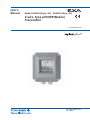
Model PH202G [Style: S3], PH202S [Style: S3]
2-wire Type pH/ORP(Redox)
Transmitter
IM 12B07D02-01E
IM 12B07D02-01E
11th Edition
TABLE OF CONTENTS
PREFACE
1. Introduction And General Description.............................................................. 1-1
1-1. Instrument check............................................................................................. 1-1
1-2. Application....................................................................................................... 1-3
2. PH202 Specifications ......................................................................................... 2-1
2-1. General ........................................................................................................ 2-1
2-2. Operating specifications.................................................................................. 2-2
2-3. Model and suffix codes.................................................................................... 2-6
2-4. Control Drawing of PH202S mA HART® Specification (IECEx)...................... 2-7
2-5. Control Drawing of PH202S mA HART® Specification (ATEX)....................... 2-8
2-6. Control Drawing of PH202S mA HART® Specification ........................................
(FM Intrinsically safe design)............................................................................ 2-9
2-7. Control Drawing of PH202S mA HART® Specification ........................................
(FM Non-incendive design)............................................................................. 2-10
2-8. Control Drawing of PH202S mA HART® Specification (CSA)........................2-11
2-9. Control Drawing of PH202S FF/PB Specification (IECEx)............................ 2-12
2-10. Control Drawing of PH202S FF/PB Specification (ATEX)........................... 2-13
2-11. Control Drawing of PH202S FF/PB Specification ...............................................
(FM Intrinsically safe Entity)............................................................................ 2-14
2-12. Control Drawing of PH202S FF/PB Specification ...............................................
(FM Intrinsically safe FISCO).......................................................................... 2-16
2-13. Control Drawing of PH202S FF/PB Specification ...............................................
(FM Non-incendive Entity).............................................................................. 2-18
2-14. Control Drawing of PH202S FF/PB Specification ...............................................
(FM Non-incendive FNICO)............................................................................ 2-19
2-15. Control Drawing of PH202S FF/PB Specification (CSA)............................. 2-20
3. Installation And Wiring....................................................................................... 3-1
3-1. Installation and dimensions............................................................................. 3-1
3-1-1. Installation site..................................................................................................................3-1
3-1-2. Mounting methods............................................................................................................3-1
3-2. Preparation...................................................................................................... 3-3
3-2-1. Cables, terminals and glands...........................................................................................3-3
3-3. Wiring of sensors............................................................................................. 3-4
3-3-1. General precautions.........................................................................................................3-4
3-3-2. Additional precautions for installations in hazardous areas ............................................3-4
3-3-3.Installation in: Hazardous Area-Non-Incendive ...............................................................3-5
3-3-4. Liquid earth.......................................................................................................................3-5
3-3-5. Access to terminal and cable entry..................................................................................3-5
3-4. Wiring of power supply.................................................................................... 3-5
3-4-1. General precautions ........................................................................................................3-5
3-4-2. Connection of the power supply.......................................................................................3-6
3-4-3. Switching the instrument on.............................................................................................3-6
3-5. Wiring the sensor system................................................................................ 3-7
3-5-1. Impedance measurement jumper settings.......................................................................3-7
3-6. Sensor wiring................................................................................................... 3-8
3-6-1.
3-6-2.
3-6-3.
3-6-4.
Connection cable..............................................................................................................3-9
Sensor cable connection with special grommet.............................................................3-10
Sensor cable connections using junction box (BA10) and extension cable (WF10)....3-11
Connection VP type sensor............................................................................................3-11
In this manual a mA sign appears if it concerns the PH202G (S)-E, -C, -U, -N, -K
IM 12B07D02-01E
11th Edition: Oct. 2009(YK)
All Rights Reserved , Copyright © 2000, Yokogawa Electric Corporation
IM 12B07D02-01E
4. Operation; Display Functions And Setting ...................................................... 4-1
4-1. Operator interface ........................................................................................... 4-1
4-2. Explanation of operating keys......................................................................... 4-2
4-3. Setting passcodes .......................................................................................... 4-3
4-3-1. Passcode protection ........................................................................................................4-3
4-4. Display examples............................................................................................ 4-3
4-5. Display functions ............................................................................................ 4-4
4-5-1. Display functions pH (default)..........................................................................................4-4
4-5-2. Display functions pH (ORP).............................................................................................4-5
4-5-3. Display functions pH (rH).................................................................................................4-6
5. Parameter setting ............................................................................................... 5-1
5-1. Maintenance mode ......................................................................................... 5-1
5-1-1.
5-1-2.
5-1-3.
5-1-4.
Manual temperature selection and adjustment ...............................................................5-2
Process temperature measuring in ORP mode...............................................................5-3
Manual activation of HOLD..............................................................................................5-4
Manual impedance check ................................................................................................5-5
5-2. Commissioning mode ..................................................................................... 5-6
5-2-1. Output range ....................................................................................................................5-7
5-2-2. Hold ..............................................................................................................................5-8
5-2-3. Service ...........................................................................................................................5-10
5-3. Notes for guidance in the use of service coded settings ...............................5-11
5-3-1.
5-3-2.
5-3-3.
5-3-4.
5-3-5.
5-3-6.
5-3-7.
5-3-8.
Parameter specific functions .........................................................................................5-11
Temperature compensation and measuring functions. .................................................5-13
Calibration functions ......................................................................................................5-15
mA output functions .......................................................................................................5-17
User interface ................................................................................................................5-19
Communication setup ....................................................................................................5-21
General .........................................................................................................................5-21
Test and setup mode ....................................................................................................5-21
6. Calibration ....................................................................................................... 6-1
6-1. Automatic calibration....................................................................................... 6-1
6-2. Manual calibration........................................................................................... 6-1
6-3. Sample calibration .......................................................................................... 6-1
6-4. Data entry ....................................................................................................... 6-1
6-5. Calibration procedures.................................................................................... 6-2
6-5-1.
6-5-2.
6-5-3.
6-5-4.
Automatic calibration .......................................................................................................6-2
Automatic calibration with HOLD active ..........................................................................6-3
Manual calibration (2nd parameter calibration) ...............................................................6-4
Sample calibration ..........................................................................................................6-6
7. Maintenance ....................................................................................................... 7-1
7-1. Periodic maintenance for the EXA transmitter ................................................ 7-1
7-2. Periodic maintenance for the sensor system .................................................. 7-1
7-3. Calibration procedures are described in step-by-step detail in chapter 6. ..........
However, follow these guidelines. .................................................................... 7-2
8. Troubleshooting ................................................................................................. 8-1
8-1. Diagnostics ..................................................................................................... 8-2
8-1-1. Off-line calibration checks ...............................................................................................8-2
8-1-2. On-line impedance checks ..............................................................................................8-2
9. Spare Parts ....................................................................................................... 9-1
IM 12B07D02-01E
10. Appendix ..................................................................................................... 10-1
10-1. User setting table ........................................................................................ 10-1
10-2. Configuration checklist for PH202G ........................................................... 10-3
10-3. Setup for sensor compatibility..................................................................... 10-4
10-3-1. General ........................................................................................................................10-4
10-3-2. Selection of measurement and reference electrode ...................................................10-4
10-3-3. Selecting a temperature sensor...................................................................................10-4
10-4. Set up for other functions............................................................................ 10-5
10-5. Set up for Pfaudler Type 18 sensor ............................................................ 10-6
10-5-1. General set up .............................................................................................................10-6
10-5-2. Calibration set up.........................................................................................................10-6
10-6. Device Description (DD) menu structure .................................................... 10-7
Glossary
11. APPENDIX 2 .....................................................................................................11-1
11-1. Preface ......................................................................................................11-1
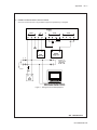
11-2. Wiring diagrams ...........................................................................................11-2
11-2-1. Example of Non-Explosionproof System ....................................................................11-2
11-2-2. Example of Intrinsically Safe Explosionproof System ................................................11-2
11-3. Sensor wiring ...............................................................................................11-2
11-3-1. Connection cable .........................................................................................................11-3
11-3-2. Sensor cable connection using terminal box ...............................................................11-5
11-4. PH201G*B Dedicated Distributor .................................................................11-5
11-4-1.
11-4-2.
11-4-3.
11-4-4.
Communication setup .................................................................................................11-5
The setting of sending WASH signal (*WASH) ..........................................................11-6
How to output manual wash signal ............................................................................11-8
Setting of errors (FAIL contact) ..................................................................................11-9
11-5. Calibration in ORP Mode ...........................................................................11-10
11-5-1 Electrode Check .........................................................................................................11-10
11-5-2. Manual Calibration .....................................................................................................11-11
11-5-3. Calibration with Sample .............................................................................................11-11
11-5-4. Data Entry ..................................................................................................................11-11
11-5-5. Calibration Procedure ................................................................................................11-12
11-6. Supplement of troubleshooting ..................................................................11-13
11-6-1.
11-6-2.
11-6-3.
11-6-4.
11-6-5.
11-6-6.
Error Codes ..............................................................................................................11-13
On-line impedance checks .......................................................................................11-14
Supplement of temperature sensor ..........................................................................11-15
Auto-Return .............................................................................................................11-15
CALEND ...................................................................................................................11-15
How to cancel sample calibration .............................................................................11-15
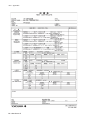
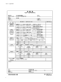
12. Appendix 3 QUALITY INSPECTION............................................................... 12-1
12-1. PH202G, PH202SJ 2-Wire pH/ORP Transmitter ........................................ 12-1
12-2. PH202S 2-Wire pH/ORP Transmitter ......................................................... 12-5
12-3. PH202G, PH202S 2-Wire pH/ORP Transmitter .................................................
(Fieldbus Communication) ............................................................................. 12-9
12-4. PH202G, PH202S 2-Wire pH/ORP Transmitter .................................................
(Profibus Communication) ........................................................................... 12-13
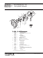
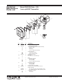
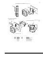
Customer Maintenance Parts List (PH202G Style : S3) ........CMPL 12B07D02-03E
Customer Maintenance Parts List (PH202S Style : S3).........CMPL 12B07D02-23E
Revision Rcord ............................................................................................................i
IM 12B07D02-01E
IM 12B07D02-01E
PREFACE
DANGER
Electric discharge
The EXA analyzer contains devices that can be
damaged by electrostatic discharge. When servicing this equipment, please observe proper procedures to prevent such damage. Replacement
components should be shipped in conductive packaging. Repair work should be done at grounded
workstations using
grounded soldering irons and wrist straps to avoid
electrostatic discharge.
Installation and wiring
The EXA analyzer should only be used with equipment that meets the relevant international and
regional standards. Yokogawa accepts no responsibility for the misuse of this unit.
CAUTION
The instrument is packed carefully with shock
absorbing materials, nevertheless, the instrument
may be damaged or broken if subjected to strong
shock, such as if the instrument is dropped. Handle
with care.
Although the instrument has a weatherproof
construction, the transmitter can be harmed if it
becomes submerged in water or becomes excessively wet.
Do not use an abrasive material or solvent when
cleaning the instrument.
Do not modify the PH202 transmitter.
WARNING
Electrostatic charge may cause an explosion hazard. Avoid any actions that cause the generation of
electrostatic charge, e.g., rubbing with a dry cloth.
Warning label
Because the enclosure of the pH/ORP transmitter
Type PH202S-E, -P, -F are made of aluminium, if it
is mounted in an area where the use of category
1 G Zone 0 apparatus is required, it must be
installed such, that, even in the event of rare incidents, ignition sources due to impact and friction
sparks are excluded.
Notice
• This manual should be passed on to the end
user.
• The contents of this manual are subject to
change without prior notice.
• The contents of this manual shall not be
reproduced or copied, in part or in whole,
without permission.
• This manual explains the functions contained in
this product, but does not warrant that they are
suitable the particular purpose of the user.
• Every effort has been made to ensure accuracy
in the preparation of this manual.
However, when you realize mistaken
expressions or omissions, please contact the
nearest Yokogawa Electric representative or
sales office.
• This manual does not cover the special
specifications. This manual may be left
unchanged on any change of specification,
construction or parts when the change does
not affect the functions or performance of the
product.
• If the product is not used in a manner specified
in this manual, the safety of this product may be
impaired.
Yokogawa is not responsible for damage to the
instrument, poor performance of the instrument
or losses resulting from such, if the problems are
caused by:
• Improper operation by the user.
• Use of the instrument in improper applications
• Use of the instrument in an improper
environment or improper utility program
• Repair or modification of the related instrument
by an engineer not authorized by Yokogawa.
Safety and Modification Precautions
• Follow the safety precautions in this manual
when using the product to ensure protection and
safety of the human body, the product and the
system containing the product.
IM 12B07D02-01E
The following safety symbols are used on the
product as well as in this manual.
DANGER DANGER
This symbol indicates that an operator must
follow the instructions laid out in this manual in
order to avoid the risks, for the human body, of
injury, electric shock, or fatalities. The manual
describes what special care the operator must
take to avoid such risks.
WARNING
This symbol indicates that the operator must
refer to the instructions in this manual in
order to prevent the instrument (hardware) or
software from being damaged, or a system
failure from occurring.
CAUTION
This symbol gives information essential for
understanding the operations and functions.
This symbol indicates Protective Ground
Terminal
This symbol indicates Function Ground
Terminal (Do not use this terminal as the
protective ground terminal.)
This symbol indicates Alternating current.
This symbol indicates Direct current.
IM 12B07D02-01E
Warranty and service
Yokogawa products and parts are guaranteed
free from defects in workmanship and material
under normal use and service for a period of
(typically) 12 months from the date of shipment
from the manufacturer. Individual sales organizations can deviate from the typical warranty
period, and the conditions of sale relating to the
original purchase order should be consulted.
Damage caused by wear and tear, inadequate
maintenance, corrosion, or by the effects of
chemical processes are excluded from this warranty coverage.
In the event of warranty claim, the defective
goods should be sent (freight paid) to the service
department of the relevant sales organization for
repair or replacement (at Yokogawa discretion).
The following information must be included in the
letter accompanying the returned goods:
• Part number, model code and serial number
• Original purchase order and date
• Length of time in service and a description of
the process
• Description of the fault, and the circumstances
of failure
• Process/environmental conditions that may be
related to the installation failure of the device
• A statement whether warranty or non-warranty
service is requested
• Complete shipping and billing instructions for
return of material, plus the name and phone
number of a contact person who can be
reached for further information.
Returned goods that have been in contact with
process fluids must be decontaminated/disinfected before shipment. Goods should carry a
certificate to this effect, for the health and safety
of our employees. Material safety data sheets
should also be included for all components of
the processes to which the equipment has been
exposed.
ATEX Documentation
This procedure is only applicable to the countries
in European Union.
GB
All instruction manuals for ATEX Ex related products are available in English, German and French.
Should you require Ex related instructions in your
local language, you are to contact your nearest
Yokogawa office or representative.
DK
Alle brugervejledninger for produkter relateret
til ATEX Ex er tilgængelige på engelsk, tysk og
fransk. Skulle De ønske yderligere oplysninger
om håndtering af Ex produkter på eget sprog, kan
De rette henvendelse herom til den nærmeste
Yokogawa afdeling eller forhandler.
I
Tutti i manuali operativi di prodotti ATEX contrassegnati con Ex sono disponibili in inglese,
tedesco e francese. Se si desidera ricevere i manuali operativi di prodotti Ex in lingua locale, mettersi in contatto con l’ufficio Yokogawa più vicino o
con un rappresentante.
E
Todos los manuales de instrucciones para los productos antiexplosivos de ATEX están disponibles
en inglés, alemán y francés. Si desea solicitar las
instrucciones de estos artículos antiexplosivos en
su idioma local, deberá ponerse en contacto con
la oficina o el representante de Yokogawa más
cercano.
NL
Alle handleidingen voor producten die te maken
hebben met ATEX explosiebeveiliging (Ex)
zijn verkrijgbaar in het Engels, Duits en Frans.
Neem, indien u aanwijzingen op het gebied van
explosiebeveiliging nodig hebt in uw eigen taal,
contact op met de dichtstbijzijnde vestiging van
Yokogawa of met een vertegenwoordiger.
SF
Kaikkien ATEX Ex -tyyppisten tuotteiden käyttöhjeet ovat saatavilla englannin-, saksan- ja
ranskankielisinä. Mikäli tarvitsette Ex -tyyppisten
tuotteiden ohjeita omalla paikallisella kielellännne,
ottakaa yhteyttä lähimpään Yokogawa-toimistoon
tai -edustajaan.
P
Todos os manuais de instruções referentes aos
produtos Ex da ATEX estão disponíveis em Inglês,
Alemão e Francês. Se necessitar de instruções na
sua língua relacionadas com produtos Ex, deverá
entrar em contacto com a delegação mais próxima
ou com um representante da Yokogawa.
F
Tous les manuels d’instruction des produits
ATEX Ex sont disponibles en langue anglaise,
allemande et française. Si vous nécessitez des
instructions relatives aux produits Ex dans votre
langue, veuillez bien contacter votre représentant
Yokogawa le plus proche.
D
Alle Betriebsanleitungen für ATEX Ex bezogene
Produkte stehen in den Sprachen Englisch,
Deutsch und Französisch zur Verfügung. Sollten
Sie die Betriebsanleitungen für Ex-Produkte in
Ihrer Landessprache benötigen, setzen Sie sich
bitte mit Ihrem örtlichen Yokogawa-Vertreter in
Verbindung.
S
Alla instruktionsböcker för ATEX Ex (explosionssäkra) produkter är tillgängliga på engelska, tyska
och franska. Om Ni behöver instruktioner för
dessa explosionssäkra produkter på annat språk,
skall Ni kontakta närmaste Yokogawakontor eller
representant.
GR
IM 12B07D02-01E
SK
PL
CZ
SLO
LT
H
BG
LV
EST
RO
M
IM 12B07D02-01E
Introduction 1-1
1. INTRODUCTION AND GENERAL DESCRIPTION
The Yokogawa EXA 202 is a 2-wire transmitter designed for industrial process monitoring, measurement
and control applications. This user’s manual contains the information needed to install, set up, operate
and maintain the unit correctly. This manual also includes a basic troubleshooting guide to answer typical user questions.
Yokogawa can not be responsible for the performance of the EXA analyzer if these instructions are not
followed.
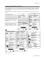
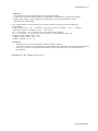
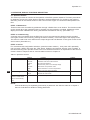
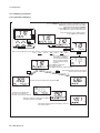
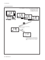
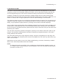
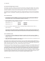
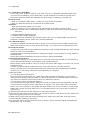
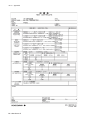
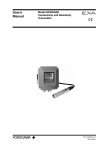
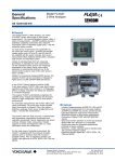
1-1. Instrument check
Upon delivery, unpack the instrument
carefully and inspect it to ensure that
it was not damaged during shipment.
If damage is found, retain the original
packing materials (including the outer
box) and then immediately notify the
carrier and the relevant Yokogawa
sales office.
Make sure the model number on the
textplate affixed to the side of the
instrument agrees with your order.
Examples of nameplates are shown.
PH/ORP TRANSMITTER
PH/ORP TRANSMITTER
MODEL
SUFFIX
PH202
MODEL
SUFFIX
SUPPLY
OUTPUT
AMB.TEMP.
24V DC
4 20mA DC
AMB.TEMP. -10 55°C
STYLE
No.
No. IECEx KEM 06.0052X
Zone 0 Ex ia IIC T4
Zone 0 Ex ia IIC T6 for Ta:40˚C
IP65
SEE CONTROL DRAWING
No. KEMA 06ATEX0218 X
II 1G Ex ia IIC T4
Ex ia IIC T6 for Ta:40˚C
SEE CONTROL DRAWING IP65
Made in Japan Tokyo 180-8750 JAPAN
Made in Japan Tokyo 180-8750 JAPAN
N200
PH/ORP TRANSMITTER
PH202S-C
II 3 G
SUPPLY
OUTPUT
AMB.TEMP.
SUPPLY
OUTPUT
24V DC
4 20mA DC
-10 55°C
AMB.TEMP.
No.
No. IECEx KEM 06.0052X
Zone 0 Ex ia IIC T4
Zone 0 Ex ia IIC T6 for Ta:40˚C
IP65
SEE CONTROL DRAWING
IS CL I, DIV 1, GP ABCD
AND AEx ia IIC
T4
Type 4X
Install per CONTROL DRAWING
IKE024-A10 P.4-1 to P.4-2
R
No. IECEx KEM 06.0052X
Zone 0 Ex ia IIC T4
Zone 0 Ex ia IIC T6 for Ta:40˚C
IP65
SEE CONTROL DRAWING
LR81741
Ex nA[nL] IIC
NI CL I, DIV 2, GP ABCD
T4
T6 for Ta:40˚C
IP65 Type 3S
SEE CONTROL DRAWING
WARNING
Substitution of
components may
impair suitability
for class I, Division 2.
CL I, DIV 1, GP ABCD
Ex ia IIC T4
R
Ex ia IIC T6 for Ta:40˚C
SEE CONTROL DRAWING
LR81741 C
IP65 Type 3S
WARNING
Substitution of
components may impair
intrinsic safety
No. IECEx KEM 06.0052X
Ex nA[nL] IIC T4
Ex nA[nL] IIC T6 for Ta:40˚C
IP65
SEE CONTROL DRAWING
No. KEMA 06ATEX0219
EEx nA[nL] IIC T4
EEx nA[nL] IIC T6 for Ta:40˚C
IP65
SEE CONTROL DRAWING
NI CL I, DIV 2, GP ABCD AND
CL I, ZN 2, GP IIC
T4
Type 4X
Install per CONTROL DRAWING
IKE024-A10 P.4-3 to P.4-4
24V DC
4 20mA DC
-10 55°C
STYLE
No.
STYLE
N200
0344
PH/ORP TRANSMITTER
MODEL
SUFFIX
PH202S-U
MODEL
SUFFIX
24V DC
4 20mA DC
-10 55°C
STYLE
No.
SUPPLY
OUTPUT
mA
PH202S-E
AVERTISSEMENT
La substitution de composants
peut compromeltre la securite
intrinseque.
AVERTISSEMENT
La substitution de composants
peut rendre ce materiel
inacceptable pour les
emplacements de
Classe I, Division 2.
PH202S-N
Made in Japan
Made in Japan
N200
N200
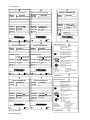
Figure 1-1. Nameplate
IM 12B07D02-01E
1-2 Introduction
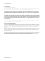
DISSOLVED OXYGEN TRANSMITTER
MODEL
SUFFIX
SUPPLY
OUTPUT
AMB.TEMP.
MODEL
SUFFIX
PH202G-F
SUPPLY
OUTPUT
9 TO 32VDC
FF-TYPE113
-10 55°C
AMB.TEMP.
PH202G-P
9 TO 32VDC
PROFIBUS-PA
-10 55°C
STYLE
No.
Made in Japan Tokyo 180-8750 JAPAN
N200
MODEL
SUFFIX
SUPPLY FISCO
17.5VDC
or 24VDC
AMB.TEMP.
FISCO field device
PH/ORP TRANSMITTER
PH202S-F
No. IECEx KEM 07.0026X
Zone 0 Ex ia IIC T4
IP65
SEE CONTROL DRAWING
PH202S-P
II 1G
SUPPLY FISCO
/380mA/5.32W
17.5VDC
or 24VDC
/250mA/1.2W
/380mA/5.32W
FF-TYPE111 or 511
Li=0 μH, Ci=220pF
OUTPUT
PROFIBUS-PA
Li=0 μH, Ci=220pF
AMB.TEMP.
-10 55°C
AMB.TEMP.
-10 55°C
STYLE
No.
R
LR81741 C
Made in Japan Tokyo 180-8750 JAPAN
0344
PH/ORP TRANSMITTER
MODEL
SUFFIX
PH202S-B
PH202S-F/-P
FNICO field device
PH/ORP TRANSMITTER
PH202S-D
II 3 G
SUPPLY
OUTPUT
AMB.TEMP.
9 TO 32VDC
FF-TYPE 113
-10 55°C
SUPPLY
OUTPUT
AMB.TEMP.
STYLE
No.
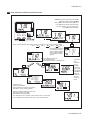
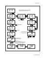
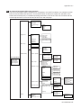
Figure 1-2. Nameplate
IM 12B07D02-01E
9 TO 32VDC
PROFIBUS-PA
-10 55°C
R
LR81741 C
Made in Japan Tokyo 180-8750 JAPAN
N200
No. IECEx KEM 07.0026X
Ex nA[nL] IIC T4
Ex nA[nL] IIC T6 for Ta:40°C
IP65
SEE CONTROL DRAWING
No. KEMA 07ATEX0049
EEx nA[nL] IIC T4
EEx nA[nL] IIC T6 for Ta:40°C
IP65
SEE CONTROL DRAWING
NI CL I, DIV 2, GP ABCD AND
CL I, ZN 2, GP IIC
T4
Type 4X
Install per CONTROL DRAWING
IKE025-A10 P.8 to P.9
STYLE
No.
Made in Japan Tokyo 180-8750 JAPAN
AVERTISSEMENT
La substitution de composants
peut compromeltre la securite
intrinseque.
N200
0344
MODEL
SUFFIX
CL I, DIV 1, GP ABCD
Ex ia IIC T4
SEE CONTROL DRAWING
IP65 Type 3S
WARNING
Substitution of
components may impair
intrinsic safety
Made in Japan Tokyo 180-8750 JAPAN
N200
No. KEMA 07ATEX0048 X
Ex ia IIC T4 IP65
SEE CONTROL DRAWING
IS CL I, DIV 1, GP ABCD
AND AEx ia IIC
T4 Type 4X
Install per CONTROL DRAWING
IKE025-A10 P.4 to P.7
/250mA/1.2W
OUTPUT
STYLE
No.
24V DC
4 20mA DC
-10 55°C
Cert No. GYJ081156X
Ex ia IIC T4
Ex ia IIC T6 for Ta:40˚C
SEE USER’S MANUAL BEFORE USE
N200
PH/ORP TRANSMITTER
PH202S-K
SUPPLY
OUTPUT
Made in Japan Tokyo 180-8750 JAPAN
Made in Japan Tokyo 180-8750 JAPAN
MODEL
SUFFIX
MODEL
SUFFIX
STYLE
No.
STYLE
No.
PH/ORP TRANSMITTER
DISSOLVED OXYGEN TRANSMITTER
N200
Ex nA[nL] IIC
NI CL I, DIV 2, GP ABCD
T4
T6 for Ta:40°C
IP65 Type 3S
SEE CONTROL DRAWING
WARNING
Substitution of
components may
impair suitability
for class I, Division 2.
PH202S-B/-D
AVERTISSEMENT
La substitution de composants
peut rendre ce materiel
inacceptable pour les
emplacements de
Classe I, Division 2.
Introduction 1-3
NOTE: Check that all the parts are present, including mounting hardware, as specified in the option
codes at the end of the model number.
For a description of the model codes, refer to Chapter 2 of this manual under General
Specifications.
Basic Parts List: Transmitter PH202
User’s Manual English
Optional mounting hardware when specified (See model code)
NOTE: mounting screws and special grommet are packed in the terminal compartment, together with a
second link for impedance selection.
1-2. Application
The EXA converter is intended to be used for continuous on-line measurement in industrial installations.
The unit combines simple operation and microprocessor-based performance with advanced self-diagnostics and enhanced communications capability to meet the most advanced requirements. The measurement can be used as part of an automated process control system. It can also be used to indicate
dangerous limits of a process, to monitor product quality, or to function as a simple controller for a dosing/neutralization system.
Yokogawa designed the EXA analyzer to withstand harsh environments. The converter may be installed
either indoors or outside because the IP65 (NEMA 4X) housing and cabling glands ensure the unit is
adequately protected. The flexible polycarbonate window on the front door of the EXA allows pushbutton access to the keypad, thus preserving the water and dust protection of the unit even during routine
maintenance operations.
A variety of EXA hardware is optionally available to allow wall, pipe, or panel mounting. Selecting a proper installation site will permit ease of operation. Sensors should normally be mounted close to the converter in order to ensure easy calibration and peak performance. If the unit must be mounted remotely
from the sensors, WF10 extension cable can be used up to a maximum of 50 metres (150 feet) with a
BA10 junction box. Except installations with dual high impedance sensors, where the maximum cable
length is 20 metres using integral cable only (no junction box).
The EXA is delivered with a general purpose default setting for programmable items. (Default settings
are listed in Chapter 5 and again in Chapter 10). While this initial configuration allows easy start-up, the
configuration should be adjusted to suit each particular application. An example of an adjustable item
is the type of temperature sensor used. The EXA can be adjusted for any one of eight different types of
temperature sensors.
To record such configuration adjustments, write changes in the space provided in Chapter 10 of this
manual. Because the EXA is suitable for use as a monitor, a controller or an alarm instrument, program
configuration possibilities are numerous.
Details provided in this user’s manual are sufficient to operate the EXA with all Yokogawa sensor
systems and a wide range of third-party commercially available probes. For best results, read this manual in conjunction with the corresponding sensor user’s manual.
IM 12B07D02-01E
1-4 Introduction
IM 12B07D02-01E
Specification 2-1
2. PH202 Specifications
with key diagnostic information available in the
display.
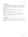
2-1. General
mA D. Output signal
: 4-20 mA loop powered, isolated from input,
maximum load 425 Ω at 24 V DC. With the
possibility of 21 mA “FAIL” signal (burn up)
and 3.6 mA (burn down when HART® or
distributor comm. is non-used), 3.9 mA (burn
down when HART® or distributor comm. is
used).
E. Temperature compensation
- Range
:–30 ºC to 140 ºC
(for 8.55kΩ sensor –10 ºC to 120 ºC)
Sensor types: Pt100, Pt1000, 3kΩ PTC, 5.1kΩ
PTC, 8.55kΩ NTC, 350Ω PTC,
6.8kΩ PTC, 10kΩ PTC
Automatic or manual compensation to Nernst
equation. Process compensation by configurable coefficient. Adjustable ITP (Iso-thermal point
of intersection).
F. Calibration
: Semi-automatic, using tables in transmitter
for pH 4, 7 & 9 buffer solutions, or using userdefined tables, with automatic check of measurement stability.
Manual, using standard sample, by correcting
reading to value of standard.
Calibration by slope and asymmetry potential
setting. (IEC746-2)
I. Display
: Custom liquid crystal display, with a main display of 3 1/2 digits 12.5 mm high.
Message display of 6 alphanumeric characters, 7 mm high.
Warning flags and units (pH and mV).
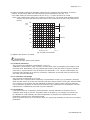
J. Power supply
: Nominal 24 volt DC loop powered system.
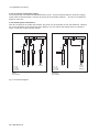
- PH202G : 17 to 40 volts, see Fig. 2-1.
- PH202S : 17 to 31.5 volts, see Fig. 2-2.
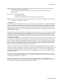
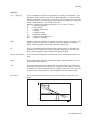
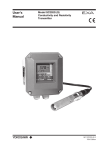
K. Maximum load resistance:
For the PH202G, see Fig. 2-1.
For the PH202S, see Fig. 2-2.
Load Resistance (Ω)
B. Input ranges - pH : -2 to 16 pH
- ORP : -1500 to 1500 mV
- rH
: 0 to 55 rH
- Temperature : -30ºC to 140ºC (-20 to 300ºF)
- 8k55Ω NTC sensor: -10ºC to 120ºC (10 to
250 ºF)
- 10kΩ PTC: -20ºC to 140ºC (0 to 300ºF)
C. Output ranges
- pH
: min 1
max 20 pH
- ORP : min 100
max 3000 mV
- rH
: min 2
max 55 rH
- Temperature : min. 25 ºC max. 200 ºC
(for 8.55kΩ NTC sensor max. 120 ºC )
H. Serial communication
: Bi-directional HART® digital communication
superimposed on the 4-20 mA signal.
1150
1000
800
600
400
200
180
0
Possible
0
17 18 20
25
30
35
40
Voltage (V)
F2.1E.eps
Fig. 2-1. Supply voltage/ load diagram for the PH202G
800
Load Resistance (Ω)
A. Input specifications
: Dual high impedance inputs (2 x 10¹²Ω) with
provision for liquid earth connection. Suitable
for inputs from glass or enamel pH & reference sensors and ORP metal electrodes.
775
600
425
400
Possible
200
0
12
17
16
20
24
28
32
31.5 V
Voltage (V)
Fig. 2-2. Minimum terminal voltage for the PH202S
(Note) In this manual a mA sign appears if it concerns the PH202G (S)-E, -C, -U, -N, -K.
G. Logbook
:S
oftware record of important events and diagnostic data. Available through HART® link,
IM 12B07D02-01E
2-2 Specification
2-2. Operating specifications
A. Performance : pH
- Linearity :
±0.01 pH
- Repeatability:
±0.01 pH
- Accuracy :
±0.01 pH
Performance : ORP
- Linearity :
±1 mV
- Repeatability :
±1 mV
- Accuracy :
±1 mV
Performance : Temperature with Pt1000 Ω,
3kΩ Balco, 5k1Ω, 350Ω, 6k8Ω, PTC10kΩ &
8k55Ω
- Linearity :
±0.3 ˚C
- Repeatability:
±0.1 ˚C
- Accuracy :
±0.3 ˚C
Performance : Temperature with Pt100 Ω
- Linearity :
±0.4 ˚C
- Repeatability:
±0.1 ˚C
- Accuracy :
±0.4 ˚C
Note on performance specifications:
The following tolerance is added to above
performance.
mA output tolerance : ± 0.02 mA of
"4 - 20 mA"
B. Ambient operating temperature
: -10 to + 55 ˚C (10 to 131 ˚F)
C. Storage temperature
: -30 to +70 ˚C (-20 to 160 ˚F)
D. Humidity
: 10 to 90% RH (Non-condensing)
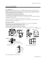
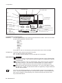
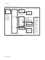
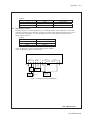
F. Housing:
Case: Cast aluminum case with chemically
resistant coating
Cover: Polycarbonate window.
Case color: Off-white (Equivalent to Munsell
2.5Y8.4/1.2)
Cover color: Deep sea Moss green
(Equivalent to Munsell 0.6GY3.1/2.0)
Sensor
cable gland
Grounding
terminal
Power/Output
cable gland
Cable and terminals :
The PH202 is equipped with terminals
suitable for the connection of finished
cables in the size: 0.13 to 2.5 mm (26 to
14 AWG)
Cable entry: 2 cable glands 1/2NPT. The cable
glands will form a tight seal on cables with
an outside diameter in the range of 6 to 12
mm (0.24 to 0.47 inches).
Construction : Weather resistant to IP65 and
NEMA 4X standards
Mounting : Pipe, wall or panel mounting, using
optional hardware
Weight : Approx. 1.6 kg
G. Shipping details
: Package size w x h x d
290 x 300 x 290 mm.
11.5 x 11.8 x 11.5 in.
Packed weight approx. 2.5 kg (5lb)
H. Data protection
: EEPROM for configuration and logbook, and
lithium cell for clock.
I. Watchdog timer
: Checks microprocessor
J. Automatic safeguard
: Return to measuring mode when no keystroke
is made for 10 min.
K. Operation protection
: 3-digit programmable password.
L. Sensor impedance checking
: Independent impedance check on measuring
and reference sensor elements, with
temperature compensation. Display of sensor
impedance on message line of display. FAIL
flag in event of “out of limits” impedance, and
the possibility of 21 mA or (3.6 mA or 3.9 mA)
error signal.
M. Signal processing (pH/ORP)
: The PH202 can measure pH or ORP. Using
the FU20 allows simultaneous measurement
and display of pH and ORP. It also allows
display and out put of pH.
N. EMC Conformity standards
,
EN 61326-1 Class A, Table 2
(For use in industrial locations)
EN 61326-2-3
EN 61326-2-5 (pending)
CAUTION
This instrument is a Class A product, and it is
designed for use in the industrial environment.
Please use this instrument in the industrial
environment only.
IM 12B07D02-01E
Specification 2-3
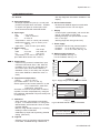
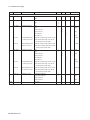
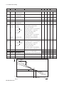
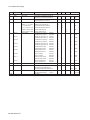
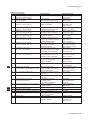
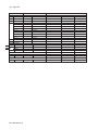
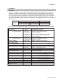
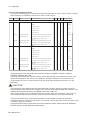
O. Intrinsically safe
Refer to conrol drawings.
mA
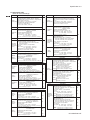
Item
Description
FM Intrinsically safe Approval
Applicable standard: FM3600, FM3610, FM3810
Intrinsically Safe for Class I, Division 1, Groups ABCD
Class I, Zone 0, AEx ia IIC
Factory
Mutual (FM) Temp. Class: T4, Amb. Temp.: -10 to 55°C
Intrinsically Safe Apparatus Parameters
Vmax=31.5 V, Imax=100 mA,
Pmax=1.2 W, Ci=22 nF, Li=35 μH
IECEx
(Note)
IECEx
Scheme
Item
CENELEC
ATEX
Entity
CENELEC
ATEX
FISCO
CENELEC
ATEX
IECEx Intrinsically safe
Applicable standard: IEC60079-0, IEC60079-11,
IEC60079-26
Certificate: IECEx KEM 06.0052X
Zone 0 Ex ia IIC
Temp. Class: T4, Amb. Temp.: -10 to 55°C
T6, Amb. Temp.: -10 to 40°C
Ui=31.5 V, Ii=100 mA, Pi=1.2 W, Ci=22 nF, Li=35 μH
Description
CENELEC ATEX (KEMA) Intrinsically safe Approval
Applicable standard: EN60079-0, EN50020
EN60079-26
Certificate: KEMA 07ATEX0048 X
Ex ia IIC, Group: II, Category: 1G
Temp. Class: T4, Amb. Temp.: -10 to 55°C
Ui=24 V, Ii=250 mA, Pi=1.2 W, Ci=220 pF, Li=0 μH
CENELEC ATEX (KEMA) Intrinsically safe Approval
Applicable standard: EN60079-0, EN50020
EN60079-26, EN60079-27
Certificate: KEMA 07ATEX0048 X
Ex ia IIC, Group: II, Category: 1G
Temp. Class: T4, Amb. Temp.: -10 to 55°C
Ui=17.5 V, Ii=380 mA, Pi=5.32 W, Ci=220 pF, Li=0 μH
CENELEC ATEX (KEMA) Type of protection "n"
Applicable standard: EN60079-0:2006,
EN60079-15:2003
Certificate: KEMA 07ATEX0049
EEx nA [nL] IIC, Group: II, Category: 3G
Temp. Class: T4, Amb. Temp.: -10 to 55°C
T6, Amb. Temp.: -10 to 40°C
Ui=32 V, Ci=220 pF, Li=0 μH
IECEx
Scheme
Entity
CENELEC
ATEX
CENELEC ATEX (KEMA) Type of protection "n"
Applicable standard: EN60079-0:2006,
EN60079-15:2003
Certificate: KEMA 06ATEX0219
EEx nA [nL] IIC, Group: II, Category: 3G
Temp. Class: T4, Amb. Temp.: -10 to 55°C
T6, Amb. Temp.: -10 to 40°C
Ui=31.5 V, Ci=22 nF, Li=35 μH
Canadian
Standards
Association
(CSA)
CSA Non-incendive safe Approval or
type of protection "n"
Applicable standard: C22.2, No.0-M1991,
C22.2, No.04-M2004, C22.2, No.157-M1992,
C22.2, No.213-M1987, C22.2, No.61010-1
Class I, Division 2, Groups ABCD
Ex nA [nL] IIC
Temp. Class: T4, Amb. Temp.: -10 to 55°C
T6, Amb. Temp.: -10 to 40°C
Ui(Vmax)=31.5 V, Ci=22 nF, Li=35 μH
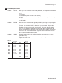
IECEx
Scheme
IECEx Type of protection "n"
Applicable standard: IEC 60079-15:2001,
IEC 60079-0:2004
Certificate: IECEx KEM 06.0052X
Ex nA [nL] IIC
Temp. Class: T4, Amb. Temp.: -10 to 55°C
T6, Amb. Temp.: -10 to 40°C
Ui=31.5 V, Ci=22 nF, Li=35 μH
Description
IECEx Intrinsically safe
Applicable standard: IEC 60079-0, IEC60079-11,
IEC60079-26
Certificate: IECEx KEM 07.0026X
Zone 0 Ex ia IIC
Temp. Class: T4, Amb. Temp.: -10 to 55°C
Ui=24 V, Ii=250 mA, Pi=1.2 W, Ci=220 pF, Li=0 μH
IECEx
Scheme
FISCO
IECEx Intrinsically safe
Applicable standard: IEC 60079-0, IEC60079-11,
IEC60079-26, IEC60079-27
Certificate: IECEx KEM 07.0026X
Zone 0 Ex ia IIC
Temp. Class: T4, Amb. Temp.: -10 to 55°C
Ui=17.5 V, Ii=380 mA, Pi=5.32 W, Ci=220 pF, Li=0 μH
IECEx
Scheme
IECEx Type of protection "n"
Applicable standard: IEC 60079-15:2001,
IEC 60079-0:2004
Certificate: IECEx KEM 07.0026X
Ex nA [nL] IIC
Temp. Class: T4, Amb. Temp.: -10 to 55°C
T6, Amb. Temp.: -10 to 40°C
Ui=32 V, Ci=220 pF, Li=0 μH
-N
T2.EPS
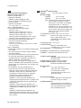
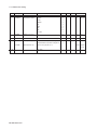
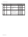
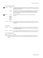
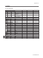
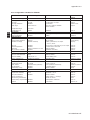
Item
T1E.EPS
Code
-P
Factory
Mutual (FM)
Description
Code
FM Intrinsically safe Approval
Applicable standard: FM3600, FM3610, FM3810
Intrinsically Safe for Class I, Division 1, Groups ABCD
Class I, Zone 0, AEx ia IIC
Temp. Class: T4, Amb. Temp.: -10 to 55°C
Intrinsically Safe Apparatus Parameters
Vmax=24 V, Imax=250 mA,
Entity
Pmax=1.2 W, Ci=220 pF, Li=0 μH
Vmax=17.5 V, Imax=380 mA,
FISCO
Pmax=5.32 W, Ci=220pF, Li=0 μH
FM Non-incendive safe Approval
Applicable standard: FM3600, FM3611, FM3810
Non-incendive Safe for Class I, Division 2,
Groups ABCD, Zone 2
Temp. Class: T4, Amb. Temp.: -10 to 55°C
Non-incendive Safe Apparatus Parameters
Vmax=32 V, Pmax=1.2 W,
Entity
Ci=220 pF, Li=0 μH
Vmax=32 V, Pmax=5.32 W,
FNICO Ci=220 pF, Li=0 μH
or
-F
-B
-P
or
-F
-B
or
-D
FM.EPS
or
-D
ATEX.EPS
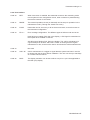
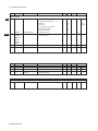
Item
Code
Factory
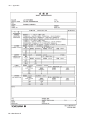
Mutual (FM)
-C
IECEx Intrinsically safe (see Note)
Description
FM Non-incendive safe Approval
Applicable standard: FM3600, FM3611, FM3810
Non-incendive for Class I, Division 2, Groups ABCD,
Zone 2
Temp. Class: T4, Amb. Temp.: -10 to 55°C
Non-incendive Safe Apparatus Parameters
Vmax=31.5 V, Ci=22 nF, Li=35 μH
-E
IECEx Intrinsically safe (see Note)
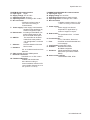
CSA Intrinsically safe Approval
Applicable standard: C22.2, No.0-M1991,
C22.2, No.04-M2004, C22.2, No.157-M1992,
C22.2, No.61010-1
Canadian
Standards Ex ia Class I, Division 1, Groups ABCD,
Association Ex ia IIC
Temp. Class: T4, Amb. Temp.: -10 to 55°C
(CSA)
T6, Amb. Temp.: -10 to 40°C
Ui(Vmax)=31.5 V, Ii(Imax)=100 mA,
Pi(Pmax)=1.2 W, Ci=22 nF, Li=35 μH
IECEx
-U
Item
IECEx Intrinsically safe (see Note)
CENELEC ATEX (KEMA) Intrinsically safe Approval
Applicable standard: EN60079-0, EN50020,
EN60079-26
CENELEC Certificate: KEMA 06ATEX0218 X
Ex ia IIC, Group: II, Category: 1G
ATEX
Temp. Class: T4, Amb. Temp.: -10 to 55°C
T6, Amb. Temp.: -10 to 40°C
Ui=31.5 V, Ii=100 mA, Pi=1.2 W, Ci=22 nF, Li=35 μH
IECEx
Code
Code
-P
or
-F
-B
Item
Description
Code
CSA Intrinsically safe Approval
Applicable standard: C22.2, No. 0-M1991,
C22.2, No. 04-M2004, C22.2, No. 157-M1992,
C22.2, No. 61010-1
Ex ia Class I, Division 1, Groups ABCD
Ex ia IIC
Temp. Class: T4, Amb. Temp.: -10 to 55°C
Ui(Vmax)=24 V, Ii(Imax)=250 mA,
Entity
Canadian
Pi(Pmax)=1.2 W, Ci=220 pF, Li=0 μH
Standards
Ui(Vmax)=17.5 V, Ii(Imax)=380 mA,
Association FISCO Pi(Pmax)=5.32 W, Ci=220 pF, Li=0 μH
(CSA)
CSA Non-incendive safe Approval or
type of protection "n"
Applicable standard: C22.2, No.0-M1991,
C22.2, No.04-M2004, C22.2, No.157-M1992,
C22.2, No.213-M1987, C22.2, No. 61010-1
Class I, Division 2, Groups ABCD
Ex nA [nL] IIC
Temp. Class: T4, Amb. Temp.: -10 to 55°C
T6, Amb. Temp.: -10 to 40°C
Entity: Ui(Vmax)=32 V, Ci=220 pF, Li=0 μH
FNICO: Ui(Vmax)=32 V, Ci=220 pF, Li=0 μH
-P
or
-F
-B
or
-D
CSA.EPS
or
-D
IEC.EPS
IM 12B07D02-01E
2-4 Specification
mA
NEPSI Certification (PH202S-K)
mA mA-HART® communication
A. Input
: Two wire system 4-20 mA
NEPSI Intrinsically Safe Type
Cert No. GYJ081156X
• Applicable Standard:
GB3836.1-2000, GB3836.4-2000
• Type of Protection and Marking Code:
Ex ia IIC T4/T6
• Ambient Temperature :
T6; –10 to 40°C, T4; –10 to 55°C
Note 1 Entity Parameters
• Intrinsically safe input parameters
(terminal + and -):
Maximum Input Voltage (Ui) = 31.5 V
Maximum Input Current (Ii) = 100 mA
Maximum Input Power (Pi) = 1.2 W
Maximum Internal Capacitance (Ci) = 22 nF
Maximum Internal Inductance (Li) = 35 μH
• Intrinsically safe output parameters and
maximum external parameters
(terminal 11 and 17):
Uo=14.4 V, Io=32.3 mA, Po=0.12 W, Co=600
nF, Lo=34 mH
Note 2 Installation
• Electrostatic charges on the display window shall
be avoided.
• The external earth connection facility shall be
connected reliably.
• The instrument modification or parts replacement
by other than authorized representative of
Yokogawa Electric Corporation and will void
NEPSI Intrinsically safe certification.
• The user shall not change the configuration in
order to maintain/ensure the explosion protection
performance of the equipment. Any change may
impair safety.
• For installation, use and maintenance of
the product, the end user shall observe the
instruction manual and the following standards:
GB50257-1996 "Code for construction and
acceptance of electric device for explosion
atmospheres and fire hazard electrical
equipment installation engineering''.
GB3836.13-1997 "Electrical apparatus for
explosive gas atmospheres Part 13: Repair and
overhaul for apparatus used in explosive gas
atmospheres".
GB3836.15-2000 "Electrical apparatus for
explosive gas atmospheres- Part 15: Electrical
installations in hazardous area (other than
mines)" .
GB3836.16-2006 "Electrical apparatus for
explosive gas atmospheres- Part 16: lnspection
and maintenance of electrical installation (other
than mines)".
IM 12B07D02-01E
B. Power supply :
PH202G :
up to 40 volts
PH202S :
up to 31.5 volts
Note: The transmitter contains a switched
power supply, drawing its energy
from the 0-4 mA section of the signal.
Consequently the 17 volt limit is
applied at 4 mA. The characteristic of
the unit is such that above about 7 mA
on the output, the terminal voltage can
drop to 14.5 volts without problem.
(see figure 2-2)
C. Transmission: Isolated output of 4 to 20 mA DC.
D. Signal
: Maximum load 425Ω. (see figure 2-1)
Burn to signal failure acc.
NAMUR Recommendation NE43
(18.01.1994)
E. Operating range : 3.9 to 21mA
F. Communication
: HART®, 1200 Baud, FSK
modulated on 4 to 20 mA signal
G. Configuration : Local with 6 keys
H. Software : Firmware based on Yokogawa stack.
I. Hardware : Yokogawa HART® Modem F9197UB
J. Other Control systems
: Yokogawa PRM, Rosemount AMS,
Siemens PDM
K. Hand Terminal : Rosemount HHT 275/375
L. Other control systems: Yokogawa PRM,
Rosemount AMS, Siemens PDM
M. Output span
:
- pH
: min 1 pH, max 20 pH.
(max 90% zero suppression)
:The instrument is user
programmable for linear or nonlinear pH ranges.
N. Cable specification
: 0.5 mm diameter or 24 AWG over
maximum length of 1500 m
O. DD specification
: The PH202 Device Description is
available enabling communications
with the Handheld Communicator
and compatible devices.
Specification 2-5
PROFIBUS-PA communications
A. Input signal: Digital
B. Supply voltage: 9 to 32 V DC
C. Operating current: 26.0 mA
D. Operating values: According to IEC 1158-2
E. Bus connection
: Fieldbus interface base on
IEC1158-2 according to
FISCO-Model
F. Power supply: Power supply is achieved dependant on the application by
means of segment coupler
G. Data transfer: According to PROFIBUS- PA
profile class B based on EN
50170 and DIN 19245 part 4
H. GSD file:
The actual file can be downloaded from www.profibus.
com Configuration: Local with
6 keys
I. Software:
Firmware based on Siemens
DPC31 stack.
J. Hardware:
PC- or PCMCIA-interfaces from
Siemens
K. Other control: Siemens PDM systems
L Electrical connection:
Terminals acc. to IEC 1158-2
M. Fieldbus-cable-types:
Twisted and shielded two
wire cable according to
recommendation based on IEC
1158-2 Cable diameter: 6 to 12
mm (0.24 to 0.47 inch)
FOUNDATION FIELDBUS H1 communications
A. Input signal: Digital
B. Supply voltage: 9 to 32 V DC
C. Operating current: 26.0 mA (base current)
D. Operating values: According to IEC 1158-2
E. Bus connection
: Fieldbus interface based on IEC
1158-2 according to FISCO-Model
F. Power supply:
Power supply is achieved
dependant on application by
means of segment coupler
G. Data transfer:
FF specification Rev. 1.4 Basic
device
H. Function blocks:
3 x AI, Transducer, Resource
I. Files:
Actual file can be downloaded from
our homepage
J. Configuration: locally with 6 keys
K. Software:
National Instruments:
NI-FBUS configurator
L. Hardware: F-BUS interfaces from National
Instruments (AT-FBUS, PCMIAFBUS)
M. Other control systems:
YOKOGAWA PRM, DTM
IM 12B07D02-01E
2-6 Specification
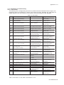
2-3. Model and suffix codes
1. 2-Wire pH/ORP Transmitter (Non-explosionproof type)
Model
Suffix Code
Option Code
2-Wire pH/ORP Transmitter (*1)
PH202G
Type
Language
Option
[Style : S3]
Description
-E
-C
-U
-P
-F
-J
-E
Mounting Hardware
Hood
Tag Plate
Conduit Adapter
/U
/PM
/H
/H2
/SCT
/AFTG
/ANSI
/TB
/X1
mA with HART (Europe type)
mA with HART (Canada type)
mA with HART (North America type)
Profibus
FF
Japanese
English
Pipe, wall mounting bracket (Stainless steel)
Panel mounting bracket (Stainless steel)
Hood for sun protection (Carbon steel)
Hood for sun protection (Stainless steel)
Stainless steel tag plate
G 1/2
1/2 NPT
Screw terminal (*2)
Epoxy baked finish (*3)
( *1) The PH202G can be also used as ORP transmitter. (Setting can be made in the field. )
( *2) It can be specified when the suffix code -A is selected.
( *3) The housing is coated with epoxy resin.
[Style : S3]
2. 2-Wire pH/ORP Transmitter (Explosionproof type)
Model
Suffix Code
Option Code
Type
Intrinsic safe mA with HART (ATEX)
Intrinsic safe mA with HART (CSA)
Intrinsic safe mA with HART (FM)
Intrinsic safe mA with HART (NEPSI)
Intrinsic safe Profibus (ATEX, CSA, FM)
Intrinsic safe FF (ATEX, CSA, FM)
Non-incendive FF (ATEX, CSA, FM) (*3)
Non-incendive mA with HART (ATEX, CSA, FM) (*3)
Non-incendive Profibus (ATEX, CSA, FM) (*3)
-E
-C
-U
-K
-P
-F
-B
-N
-D
Language
Option
Description
2-Wire pH/ORP Transmitter (*1)
PH202S
Japanese
English
-J
-E
Mounting Hardware
Hood
Tag Plate
Conduit Adapter
/U
/PM
/H
/H2
/SCT
/AFTG
/ANSI
/X1
Pipe, wall mounting bracket (Stainless steel)
Panel mounting bracket (Stainless steel)
Hood for sun protection (Carbon steel)
Hood for sun protection (Stainless steel)
Stainless steel tag plate
G 1/2
1/2 NPT
Epoxy baked finish (*2)
( *1) The PH202S can be also used as ORP transmitter. (Setting can be made in the field. )
( *2) The housing is coated with epoxy resin.
( *3) When the instrument with Suffix Code "-B,-N,-D" is used, take measures so that
the display window is not exposed to direct sunlight.
IM 12B07D02-01E
Specification 2-7
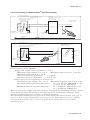
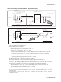
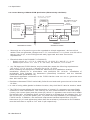
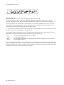
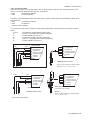
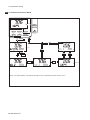
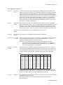
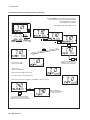
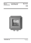
2-4. Control Drawing of PH202S mA HART® Specification (IECEx).
Intrinsically safe design
IEC-Ex standard EX ia IIC : T4 for ambient temp. < 55°C
T6 for ambient temp. < 40°C
C ertificate nr. IEC Ex KEM 06.0052X
PH202S (pH/OR P-transmitter)
EX ia or ib
C ertified safety barrier or pow er
w ith R int=300 :
(HAR T compatible)
24 volts D C N ominal
Supply V oltage.
+
+
_
SENSOR (S)
term inals 11-17
_
Uo = 31.5 Vo lt D C
Io = 100 mA
G
Functional
earth
Hazardous area
Functional
earth
Load
R esistance
Safe area
Zone 0 or 1
Intrinsically safe design
IEC Ex standard EX ia IIC : T4 for ambient temp. < 55°C
T6 for ambient temp.< 40°C
C ertificate nr. IEC Ex KEM 06.0052X
PH202S (pH/O R P-transmitter)
O utput
+
_
+
_
G
SENSOR (S)
term inals 11-17
EX ia or ib C ertified R epeater
Pow er Supply
(HAR T C ompatible)
Uo = 31.5 Volt DC
Io = 100 mA
Po = 1.2 W att
Supply
Functional
earth
Hazardous area
Safe area
Zo ne 0 or 1
・ Sensor(s) are of a passive type to be regarded as ‘simple apparatus’.
・ Electrical data of the PH202S.
- Supply and output circuit (terminals + and -):
Maximum input current I i = 100 mA.
Maximum input voltage U i = 31.5 V.
Maximum input power P i = 1.2 W.
Effective internal capacitance
C i = 22 nF.
Effective internal inductance
L i = 35 PH.
- Sensor input circuit (terminals 11 through 17):
Maximum output voltage U o = 14.4 V. Maximum output current I o = 32.3 mA.
Maximum allowed external capacitance
Co = 600 nF. (for PH202S-E,-C,-U),
Co = 3.5 PF (for PH202S-N).
Maximum allowed external inductance
Lo = 34 mH (for PH202S-E,-C,-U),
Lo = 76 mH (for PH202S-N).
・ Barriers and power supply specification must not exceed the maximum values as shown
in the diagram above. These safety descriptions cover most of the commonly used
industry standard barriers, isolators and power supplies.
・ The Hand Held Communicator must be of a IECEx certified intrinsically safe type in
case it is used on the intrinsically safe circuit in the hazardous area or of a IECEx
certified nonincendive type in case it is used in the nonincendive circuit in the
hazardous area.
IM 12B07D02-01E
2-8 Specification
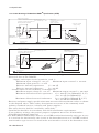
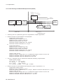
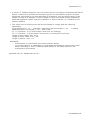
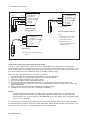
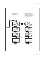
2-5. Control Drawing of PH202S mA HART® Specification (ATEX)
Intrinsically safe design
C EN ELEC standard EEX ia IIC : T4 for ambient temp. < 55°C
T6 for ambient temp. < 40°C
C ertificate nr. KEM A 06ATEX 0218 X
PH202S (pH/O R P-transmitter)
EEx ia or ib
C ertified safety barrier or pow er
w ith R int=300 :
(HAR T compatible)
24 volts D C N ominal
Supply V oltage.
+
+
_
SEN SO R (S)
term inals 11-17
Functional
earth
Hazardous area
Zone 0 or 1
Functional
earth
EEx ia or ib C ertified R epeater
Pow er Supply
(HAR T C ompatible)
O utput
+
_
+
_
G
Hazardous area
Load
R esistance
Safe area
Intrinsically safe design
C EN ELEC standard EEx ia IIC : T4 for ambient temp. < 55°C
T6 for ambient temp.< 40°C
C ertificate nr. KEM A 06ATEX 0218 X
(pH/O
R
P-transmitter)
PH202S
SEN SO R (S)
term inals 11-17
_
U o = 31.5 V o lt D C
Io = 100 mA
G
U o = 31.5 V olt D C
Io = 100 mA
Po = 1.2 W att
Supply
Functional
earth
Safe area
Zone 0 or 1
・ Sensor(s) are of a passive type to be regarded as ‘simple apparatus’.
・ Electrical data of the PH202S.
- Supply and output circuit (terminals + and -):
Maximum input voltage U i = 31.5 V.
Maximum input current I i = 100 mA.
Maximum input power P i = 1.2 W.
Effective internal capacitance
C i = 22 nF.
Effective internal inductance
L i = 35 PH.
- Sensor input circuit (terminals 11 through 17):
Maximum output voltage U o = 14.4 V. Maximum output current I o = 32.3 mA.
Maximum allowed external capacitance
Co = 600 nF. (for PH202S-E,-C,-U),
Co = 3.5 PF (for PH202S-N).
Maximum allowed external inductance
Lo = 34 mH (for PH202S-E,-C,-U),
Lo = 76 mH (for PH202S-N).
・ Barriers and power supply specification must not exceed the maximum values as shown
in the diagram above. These safety descriptions cover most of the commonly used
industry standard barriers, isolators and power supplies.
・ The safety barrier shall be certified by notify body.
・ Installation should be in accordance with local installation requirements.
・ If use ordinary wirings, the general purpose equipment must have Nonincendive
Field Wiring terminal approved.
・The Hand Held Communicator must be of a ATEX certified intrinsically safe type in case
it is used on the intrinsically safe circuit in the hazardous area or of a ATEX certified
non-incendive type in case it is used in the non-incendive circuit in the hazardous area.
IM 12B07D02-01E
Specification 2-9
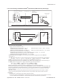
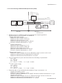
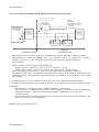
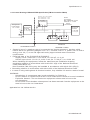
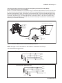
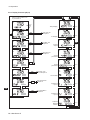
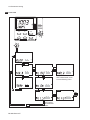
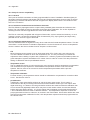
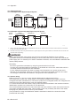
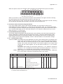
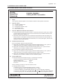
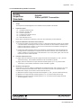
2-6. Control Drawing of PH202S mA HART® Specification (FM Intrinsically safe design)
Intrinsically safe design
FM Class I, Div.1, Group ABCD,
T4 for ambient temp. < 55°C
T6 for ambient temp. < 40°C
PH202S transmitter
FM Approved safety barrier or
power supply
with Rint = 300 :
(HART compatible)
24 volts DC Nominal
Supply Voltage.
+
+
_
-
G
Sensor(s)
For electrical data:
see text below.
terminals 11-17
Max. cablelength: 60 mtr.
Cable dia. : 3…12 mm.
Functional
earth
Classified Location
Functional
earth
Load
Resistance
Unclassified Location
Figure 1
Intrinsically safe design
FM Class I, Div.1, Group ABCD,
T4 for ambient temp. < 55°C
T6 for ambient temp. < 40°C
PH202S transmitter
FM Approved
Power Supply
(HART compatible)
Output
+
_
+
_
G
Supply
For electrical data:
Sensor(s)
see text below.
terminals 11-17
Max. cablelength: 60 mtr.
Cable dia.: 3…12 mm.
Functional
earth
Classified Location
Ùnclassified Location
Figure 2
・Electrical data of the PH202S.
-Supply circuit (terminals + and -):
Maximum input voltage Vmax = 31.5 V.
Maximum input current Imax = 100 mA.
Maximum input power Pmax = 1.2 W.
Effective internal capacitance Ci = 22 nF.
Effective internal inductance Li = 35 PH.
- Sensor input circuit (terminals 11 through 17):
Maximum output voltage Vt = 14.4 V. Maximum output current It = 32.3 mA.
Maximum allowed external capacitance Ca = 600 nF.
Maximum allowed external inductance La = 34 mH
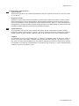
・If Hand Held Terminal (HHT) is not connected to the power supply lines of the PH202S
(see figure 1):
Any FM Approved barrier or power supply may be used that meets the following requirements.
Voc or Vt d 31.5 V ; Isc or It d 100 mA; Ca t 22nF + Ccable ; La t 35PH + Lcable
If HHT is connected to the power supply lines of the PH202S (see figure 2):
The Hand Held Terminal must be FM Approved. Refer to the manufacturers control drawing of
the HHT and the barrier/power supply to determine the cable parameters.
(Voc or Vt ) + VHHT d 31.5 V; (Isc or It ) + IHHT d 100 mA;
Ca t 22nF + Ccable+ CHHT ; La t 35PH + Lcable+ LHHT
When installing this equipment, follow the manufacturer’s installation drawing.
Installation should be in accordance with ANSI/ISA RP 12.06.01 “Installation of Intrinsically Safe
Systems for Hazardous (Classified) Locations” and the National Electrical Code (ANSI/NFPA 70).
Control equipment connected to the barrier/power supply must not use or generate more than
250 Vrms or Vdc.
・Resistance between Intrinsically Safe Ground and earth ground must be less than 1.0 Ohm.
・In case of using cable glands in Outdoor location, they shall be UV rated or made of metal.
WARNING
- Substitution of components may impair Intrinsic Safety
- To prevent ignition of flammable or combustible atmospheres, disconnect power before servicing
or read, understand and adhere to the manufacturer’s’live maintenance procedures.
Application Doc. No.: IKE024-A10 P.4-1 to P.4-2
IM 12B07D02-01E
2-10 Specification
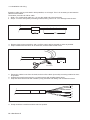
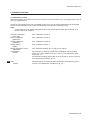
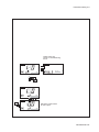
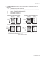
2-7. Control Drawing of PH202S mA HART® Specification (FM Non-incendive design).
N o n in c e n d iv e d e s ig n
F M C la s s I, D iv .2 , G ro u p A B C D ,
T 4 fo r a m b ie n t te m p . < 5 5 ° C
T 6 fo r a m b ie n t te m p . < 4 0 ° C
F M A p p ro ve d
p o w e r s u p p ly
V o c ≦ 3 1 .5 V D C
P H 2 0 2 S tra n s m itte r
+
+
_
-
G
S e n s o r (s )
F o r e le c t r ic a l d a t a :
s e e t e x t b e lo w .
te rm in a ls 1 1 -1 7
M a x . c a b le le n g th : 6 0 m tr .
C a b le d ia . : 3 … 1 2 m m .
F u n c tio n a l
e a r th
C la s s ifie d L o c a tio n
N o n in c e n d iv e d e s ig n
F M C la s s I, D iv .2 , G ro u p A B C D ,
Load
R e s is ta n c e
U n c la s s ifie d L o c a tio n
T 4 fo r a m b ie n t te m p . < 5 5 ° C
T 6 fo r a m b ie n t te m p . < 4 0 ° C
P H 2 0 2 S tra n s m itte r
+
+
_
-
G
F o r e le c t r ic a l d a t a :
S e n s o r (s )
s e e t e x t b e lo w .
te rm in a ls 1 1 -1 7
M a x . c a b le le n g th : 6 0 m tr .
C a b le d ia .: 3 … 1 2 m m
F M A p p ro ve d
p o w e r s u p p ly
V o c ≦ 3 1 .5 V D C
F u n c tio n a l
e a rth
C la s s ifie d L o c a tio n
Ù n c la s s ifie d L o c a tio n
・Electrical data of the PH202S.
- Supply circuit (terminals + and -):
Maximum input power Pmax = 1.2 W
Maximum input voltage Vmax = 31.5 V.
Effective internal capacitance Ci = 22 nF Effective internal inductance Li = 35 μH
- Sensor input circuit (terminals 11 through 17):
Maximum output current It = 32.3 mA.
Maximum output voltage Vt = 14.4 V.
Maximum allowed external capacitance Ca = 2.29PF.
Maximum allowed external inductance La = 64.96mH.
・The Hand Held Terminal must be FM Approved in case it is used in the classified location.
When installing this equipment, follow the manufacturers installation drawing. Installation shall
be in accordance with Article 501.4(B) of the National Electrical Code.
Non-incendive field wiring may be installed in accordance with Article 501 of the National
Electrical Code.
・ Grounding shall be in accordance with Article 250 of the National Electrical code.
・ In case of using cable glands in Outdoor location, they shall be UV rated or made of metal.
WARNING
Substitution of components may impair suitability for Division 2
Do not remove or replace while circuit is live unless area is know to be non-hazardous
Explosion Hazard – Do not disconnect equipment unless area is know to be non-hazardous
Do not reset circuit breaker unless power has been removed from the equipment or the area is
know to be non-hazardous
Application Doc. No.: IKE024-A10 P.4-3 to P.4-4
IM 12B07D02-01E
Specification 2-11
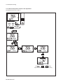
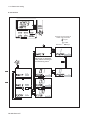
2-8. Control Drawing of PH202S mA HART® Specification (CSA).
Intrinsically safe design
C SA Ex ia C lass I, D iv.1, G roup A B C D
T4 for am bient temp. < 55°C
T6 for am bient temp. < 40°C
PH 202S (pH /O R P-transm itter)
C S A certified
safety barrier or pow er supply
(H A R T com patible)
24 volts D C N ominal
Supply V oltage.
+
+
_
Sen sor(s)
term in als 1 1 -1 7
_
G
S uitable values are:
V m ax = 31.5 V o ltD C
Imax = 100 mA
Fo r electrical data:
see text belo w .
Functional
earth
H azardous area
Load
R esistance
Safe area
Intrinsically safe design
C SA E x ia C lass I, D iv.1, G roup A B C D
T 4 for am bient tem p. < 55°C
T 6 for am bient temp. < 40°C
PH 202S
(pH /O R P-transm itter)
C SA certified
Pow er Supply
(H A R T com patible) )
O utput
+
_
Sen sor(s)
term inals 1 1 -17
Functional
earth
+
_
Suitable values are:
G
V m ax = 31.5 V o ltD C
Im ax = 100 m A
P m ax = 1.2 W att
Supply
Fo r electrical data:
see text belo w .
Functional
earth
H azardous area
Safe area
・Sensor(s) are thermocouples, RTD’s, passive resistive switch devices, or are CSA entity approved
and meet connection requirements.
・Electrical data of the PH202S.
- Supply and output circuit (terminals + and -):
Maximum input voltage Vmax = 31.5 V. Maximum input current Imax = 100 mA.
Maximum input power Pmax = 1.2 W.
Effective internal capacitance Ci = 22 nF. Effective internal inductance Li = 35 PH.
- Sensor input circuit (terminals 11 through 17):
Maximum output voltage Voc = 14.4 V. Maximum output current Isc = 32.3 mA.
Maximum allowed external capacitance Ca = 600 nF
Maximum allowed external inductance La = 34 mH.
・Barriers and power supply should be CSA certified. The specifications must not exceed
the maximum values as shown in the diagram above.
Installation should be in accordance with Canadian Electrical Code, Part I.
Maximum safe area voltage should not exceed 250 VRMS.
For Class I, Div. 2, Group ABCD the CSA certified barrier is not required, and the Sensor
input circuit (terminals 11 through 17) is non-incendive having the parameters :
Maximum output voltage Voc = 14.4 V. Maximum output current Isc = 32.3 mA.
Maximum allowed external capacitance Ca = 3.5 PF.
Maximum allowed external inductance La = 76 mH.
・The Hand Held Communicator must be of a CSA certified intrinsically safe type
in case it is used on the intrinsically safe circuit in the hazardous area, or of a
CSA certified
non-incendive type in case it is used on the non-incendive circuit in the
hazardous area.
IM 12B07D02-01E
2-12 Specification
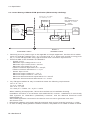
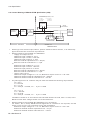
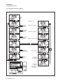
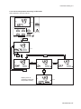
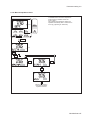
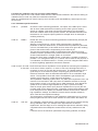
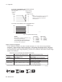
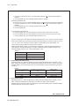
2-9. Control Drawing of PH202S FF/PB Specification (IECEx)
Ex ia IIC
T4 for ambient temp. d 55 qC
Ui = 24 V
or Ui = 17,5 V
Ii = 250 mA
Ii = 380 mA
Pi = 1,2 W
Pi = 5,32 W
PH202S-F
or PH202S-P
+
Safe area
Apparatus
+
-
I.S.
interface
Sensor
Connections
-
I.S.
certified
Term inator
I.S.
certified
Term inator
+
-
Transm itter
Safe area
+
-
Transm itter
Zone 0 or 1
Hazardous area
x
x
Sensor(s) are of a passive type to be regarded as 'simple apparatus'.
Electrical data of the PH202S-F & PH202S-P:
- Supply and output circuit:
Maximum input voltage Ui=24 V
Maximum input current Ii=250 mA
Maximum input power Pi=1.2 W
Effective internal capacitance Ci= 220 pF;
Effective internal inductance Li= 0 μ H.
or
FISCO field device
Maximum input voltage Ui=17.5 V
Maximum input current Ii=380 mA
Maximum input power Pi=5.32 W
Effective internal capacitance Ci= 220 pF;
Effective internal inductance Li= 0 μ H.
-
Sensor input circuit:
Maximum output voltage Uo=14.4 V; Maximum output current Io=32.3 mA
Maximum allowed external capacitance Co=600 nF
Maximum allowed external inductance Lo=34 mH
x
Any I.S. interface may be used that meets the following requirements:
FISCO power supply
Uo d 24 V or Uo d 17.5 V
Io d 250 mA
Io d 380 mA
Po d 1.2 W
Po d 5.32 W
Co t 220 pF + Ccable; Lo t 0 μ H + Lcable
x
Electrical data of the PH202S-B & PH202S-D (Type of protection “n”)
- Supply and output circuit:
Maximum input voltage Ui = 32 V
Effective internal capacitance Ci = 220 pF; Effective internal inductance Li = 0 μ H.
- Sensor input circuit:
Maximum output voltage Uo=14.4 V; Maximum output current Io=32.3 mA
Maximum allowed external capacitance Co = 3.5 μ F
Maximum allowed external inductance Lo = 76 mH
IM 12B07D02-01E
Specification 2-13
2-10. Control Drawing of PH202S FF/PB Specification (ATEX)
Ex ia IIC
T4 for ambient temp. d 55 qC
Ui = 24 V
or Ui = 17,5 V
Ii = 250 mA
Ii = 380 mA
Pi = 1,2 W
Pi = 5,32 W
PH202S-F
or PH202S-P
+
Safe area
Apparatus
+
-
I.S.
interface
Sensor
Connections
-
I.S.
certified
Terminator
I.S.
certified
Terminator
+
-
Transmitter
Safe area
+
-
Transmitter
Zone 0 or 1
Hazardous area
x
Sensor(s) are of a passive type to be regarded as 'simple apparatus'.
Electrical data of the PH202S-F & PH202S-P:
- Supply and output circuit:
Maximum input voltage Ui=24 V
Maximum input current Ii=250 mA
Maximum input power Pi=1.2 W
Effective internal capacitance Ci= 220 pF;
Effective internal inductance Li= 0 μH.
or
FISCO field device
Maximum input voltage Ui=17.5 V
Maximum input current Ii=380 mA
Maximum input power Pi=5.32 W
Effective internal capacitance Ci= 220 pF;
Effective internal inductance Li= 0 μH.
- Sensor input circuit:
Maximum output voltage Uo=14.4V; Maximum output current Io=32.3 mA
Maximum allowed external capacitance Co=600 nF
Maximum allowed external inductance Lo=34 mH
x
Any I.S. interface may be used that meets the following requirements:
Uo d 24 V
Io d 250 mA
Po d 1.2 W
Co t 220 pF + Ccable; Lo t 0 μ H + Lcable
or
FISCO power supply
Uo d 17.5 V
Io d 380 mA
Po d 5.32 W
Co t 220 pF + Ccable; Lo t 0 μ H + Lcable
x
Electrical data of the PH202S-B & PH202S-D (Type of protection “n”)
- Supply and output circuit:
Maximum input voltage Ui = 32 V
Effective internal capacitance Ci= 220pF; Effective internal inductance Li= 0 μH.
- Sensor input circuit:
Maximum output voltage Uo=14.4 V; Maximum output current Io=32.3 mA
Maximum allowed external capacitance Co = 3.5 μF
Maximum allowed external inductance Lo = 76 mH
IM 12B07D02-01E
2-14 Specification
2-11. Control Drawing of PH202S FF/PB Specification (FM Intrinsically safe Entity).
FM Class I, DIV. 1, Group ABCD
T4 for ambient temp. d 55 qC
Sensor
Connections
Max. cablelength: 60 mtr.
Cable dia. : 3…12 mm.
PH202S-F
or PH202S-P
+
FM Approved
barrier
Voc (Vt) d 24 V
Ioc (It) d 250 mA
Poc (Pt) d 1.2 W
Ca t 220pF+ Ccable
La t 0 H + Lcable
+
-
Sensor
Connections
-
I.S.
certified
Terminator
I.S.
certified
Terminator
+
-
Transmitter
Unclassified Location
x
x
x
+
-
Transmitter
Division 1
Classified Location
Sensor(s) are of a passive type to be regarded as 'simple apparatus', devices which neither
store nor generate voltages over 1.5 V, currents over 0.1 A, power over 25 mW or energy over
20 PJ, or are FM Approvals entity approved and meet connection requirements.
Electrical data of the PH202S-F & PH202S-P:
- Supply circuit:
Maximum input voltage Vmax = 24 V
Maximum input current Imax = 250 mA
Maximum input power Pi=1.2 W
Effective internal capacitance Ci = 220 pF;
Effective internal inductance Li = 0 PH.
- Sensor input circuit:
Maximum output voltage Vt = 14.4 V;
Maximum output current It = 32.3 mA
Maximum allowed external capacitance Ca = 600 nF
Maximum allowed external inductance La = 34 mH
Any FM Approved barrier may be used that meets the following requirements:
Voc or Vt d 24 V
Ioc or It d 250 mA
Poc or Pt d 1.2 W
Ca t 220 pF + Ccable; La t 0 μ H + Lcable
When installing this equipment, follow the manufacturer ’s installation drawing.
Installation should be in accordance with ANSI/ISA RP 12.06.01 “Installation of Intrinsically
Safe Systems for Hazardous (Classified) Locations” and the National Electrical Code
(ANSI/NFPA 70).
Associated apparatus connected to the barrier must not use or generate more than
250 Vrms or Vdc.
x Resistance between Intrinsically Safe Ground and earth ground must be less than 1.0 Ohm.
x In case of using cable glands in Outdoor location, they shall be UV rated or made of metal.
IM 12B07D02-01E
Specification 2-15
WARNING
- Substitution of components may impair Intrinsic Safety
- To prevent ignition of flammable or combustible atmospheres, disconnect power
before servicing or read, understand and adhere to the manufacturer ’s live
maintenance procedures.
x The cable used to interconnect the devices needs to comply with the following
parameters:
Loop resistance R’: 15 … 150 Ω/km; Inductance per unit length L’: 0,4 … 1 mH/km
Capacitance per unit length C’: 80 … 200 nF/km
(C’ = C’ line/line + 0,5 C’ line/screen if both line are floating)
(C’ = C’ line/line + C’ line/screen if the screen is connected to one line)
Length of spur cable: max. 30 m
Length of trunk cable: max. 1 km
Length of splice : max. 1 m
WARNING
- Substitution of components may impair Intrinsic Safety
- To prevent ignition of flammable or combustible atmospheres, disconnect power before
servicing or read, understand and adhere to the manufacturer ’s live maintenance
procedures.
Application Doc. No.: IKE025-A10 P.4 to P.5
IM 12B07D02-01E
2-16 Specification
2-12. Control Drawing of PH202S FF/PB Specification (FM Intrinsically safe FISCO)
FM Class I, DIV. 1, Group ABCD
T4 for ambient temp. d 55 qC
Sensor
Connections
Max. cablelength: 60 mtr.
Cable dia. : 3…12 mm.
Sensor
Connections
PH202S-F
or PH202S-P
+
FM Approved
FISCO barrier
Voc (Vt) d17,5 V
Ioc (It) d380 mA
Poc (Pt) d5,32 W
+
-
-
FM Approved
Terminator
R = 90..100Ω
C = 0..2,2 μF
FM Approved
Terminator
R = 90..100Ω
C = 0..2,2 μF
+
-
Transmitter
+
-
Transmitter
Division 1
Unclassified Location
Classified Location
x
Sensor(s) are of a passive type to be regarded as 'simple apparatus', devices which
neither store nor generate voltages over 1.5 V, currents over 0.1 A, power over 25 mW or
energy over 20 μJ, or are FM Approvals entity approved and meet connection
requirements.
x
Electrical data of the PH202S-F & PH202S-P:
- Supply circuit: Ui = 17.5 V; Ii = 380 mA; Pi = 5.32 W; Ci = 220 pF; Li = 0 μH.
- Sensor input circuit: Vt = 14.4 V; It = 32.3 mA; Ca =600 nF; La = 34 mH
x
Any FM Approved FISCO barrier may be used that meets the following requirements:
Voc or Vt d 17.5 V; Ioc or It d 380 mA; Poc or Pt d 5.32 W
When installing this equipment, follow the manufacturer’s installation drawing.
Installation should be in accordance with ANSI/ISA RP 12.06.01 “Installation of
Intrinsically Safe Systems for Hazardous (Classified) Locations” and the National
Electrical Code (ANSI/NFPA 70).
Associated apparatus connected to the FISCO barrier must not use or generate more
than 250 Vrms or Vdc.
x Resistance between FISCO Intrinsically Safe Ground and earth ground must be less than
1.0 Ohm.
x In case of using cable glands in Outdoor location, they shall be UV rated or made of metal.
x The FISCO concept allows the interconnection of several I.S. apparatus not specifically
examined in such combination. The criterion for such interconnection is that the voltage
(Vmax), the current (Imax) and the power (Pi) which I.S. apparatus can receive and remain
intrinsically safe, considering faults, must be equal to or greater that the voltage (Voc, Vt),
the current (Ioc, It) and the power (Poc, Pt) which can be providede by the FM approved
FISCO barrier. In addition, the maximum unprotected residual capacitance (Ci) and
inductance (Li) of each apparatus (other than the terminator) connected to the Fieldbus
must be less than or equal to 5 nF and 10 μH respectively.
IM 12B07D02-01E
Specification 2-17
x In each I.S. Fieldbus segment only one active source, normally the FM Approved FISCO
barrier, is allowed to provide the necessary power for the Fieldbus system. All other
equipment connected to the bus cable has to be passive (not providing energy to the
system), except to a leakage current of 50μA for each connected device. Seperately
powered equipment needs a galvanic isolation to insure that the I.S. Fieldbus circuit
remains passive.
x The cable used to interconnect the devices needs to comply with the following
parameters:
Loop resistance R’: 15 … 150 Ω/km; Inductance per unit length L’: 0,4 … 1 mH/km
Capacitance per unit length C’: 80 … 200 nF/km
(C’ = C’ line/line + 0,5 C’ line/screen if both line are floating)
(C’ = C’ line/line + C’ line/screen if the screen is connected to one line)
Length of spur cable: max. 30 m
Length of trunk cable: max. 1 km
Length of splice : max. 1 m
WARNING
- Substitution of components may impair Intrinsic Safety
- To prevent ignition of flammable or combustible atmospheres, disconnect power
before servicing or read, understand and adhere to the manufacturer ’s live
maintenance procedures.
Application Doc. No.: IKE025-A10 P.6 to P.7
IM 12B07D02-01E
2-18 Specification
2-13. Control Drawing of PH202S FF/PB Specification (FM Non-incendive Entity).
FM Class I, DIV. 2, Group ABCD
T4 for ambient temp. d 55 qC
T6 for ambient temp. d 40 qC
Sensor
Connections
Max. cablelength: 60 mtr.
Cable dia.: 3…12 mm.
Sensor
Connections
PH202S-B
or PH202S-D
+
FM Approved
Power Supply
Voc d 32 VDC
-
FM Approved
Terminator
R = 90..100Ω
C = 0..2,2 μF
+
-
FM Approved
Terminator
R = 90..100Ω
C = 0..2,2 μF
+
-
Transmitter
+
-
Transmitter
Division 2
Unclassified Location
Classified Location
x
Sensor(s) are of a passive type to be regarded as 'simple apparatus', devices which
neither store nor generate voltages over 1.5 V, currents over 0.1 A, power over 25 mW or
energy over 20 μJ, or are FM Approvals entity approved and meet connection
requirements.
x
Electrical data of the PH202S-B & PH202S-D:
- Supply circuit: Vmax=32 V; Pi=1.2 W; Ci= 220 pF; Li= 0 μH
- Sensor input circuit: Vt=14.4 V; It=32.3 mA; Ca=2.29 P F; La=64.96 mH
When installing this equipment, follow the manufacturers installation drawing.
Installation shall be in accordance with Article 501.4(B) of the National Electrical Code
(ANSI/NFPA 79). Nonincendive field wiring may be installed in accordance with Article
501.4(B)(3)
x Grounding shall be in accordance with Article 250 of the National Electrical code.
x In case of using cable glands in Outdoor location, they shall be UV rated or made of metal.
WARNING
- Substitution of components may impair suitability for Division 2.
- Do not remove or replace while circuit is live unless area is know to be non-hazardous
- Explosion Hazard – Do not disconnect equipment unless area is know to be
non-hazardous
- Do not reset circuit breaker unless power has been removed from the equipment or the
area is know to be non-hazardous
Application Doc. No.: IKE025-A10 P.8
IM 12B07D02-01E
Specification 2-19
2-14. Control Drawing of PH202S FF/PB Specification (FM Non-incendive FNICO)
FM Class I, DIV. 2, Group ABCD
T4 for ambient temp. d 55 qC
T6 for ambient temp. d 40 qC
Sensor
Connections
Max. cablelength: 60 mtr.
Cable dia.: 3…12 mm.
Sensor
Connections
PH202S-B
or PH202S-D
FM Approved
Power Supply
Voc d 32 VDC
+
-
+
-
FM Approved
Terminator
R = 90..100Ω
C = 0..2,2 μF
FM Approved
Terminator
R = 90..100Ω
C = 0..2,2 μF
+
-
Transmitter
+
-
Transmitter
Division 2
Unclassified Location
Classified Location
Sensor(s) are of a passive type to be regarded as 'simple apparatus', devices which
neither store nor generate voltages over 1.5 V, currents over 0.1 A, power over 25 mW or
energy over 20 PJ, or are FM Approvals entity approved and meet connection
requirements.
x Electrical data of the PH202S-B & PH202S-D:
- Supply circuit: Vmax=32 V; Pi=5.32 W; Ci= 220 pF; Li= 0 μH
- Sensor input circuit: Vt=14.4 V; It=32.3 mA; Ca = 2.29 μF; La = 64.96 mH
When installing this equipment, follow the manufacturers installation drawing.
Installation shall be in accordance with Article 501.4(B) of the National Electrical
Code (ANSI/NFPA 79).
Non-incendive field wiring may be installed in accordance with Article 501.4(B)(3)
x Grounding shall be in accordance with Article 250 of the National Electrical code.
x In case of using cable glands in Outdoor location, they shall be UV rated or made of metal.
x
WARNING
- Substitution of components may impair suitability for Division 2.
- Do not remove or replace while circuit is live unless area is know to be non-hazardous
- Explosion Hazard – Do not disconnect equipment unless area is know to be
non-hazardous
- Do not reset circuit breaker unless power has been removed from the equipment or the
area is know to be non-hazardous
Application Doc. No.: IKE025-A10 P.9
IM 12B07D02-01E
2-20 Specification
2-15. Control Drawing of PH202S FF/PB Specification (CSA).
CSA Ex ia Class I, DIV. 1, Group ABCD
T4 for ambient temp. d 55 qC
Ui = 24 V
Ii = 250 mA
Pi = 1,2 W
or
Ui = 17,5 V
Ii = 380 mA
Pi = 5,32 W
PH202S-F
or PH202S-P
+
Safe area
Apparatus
+
-
I.S.
interface
Sensor
Connections
-
I.S.
certified
Terminator
I.S.
certified
Terminator
+
-
Transmitter
Safe area
+
-
Transmitter
Zone 0 or 1
Hazardous area
x
x
x
Sensor(s) are a thermocouple, RTD's, passive resistive switch devices, or is CSA entity
approved and meet connection requirements.
Electrical data of the PH202S-F & PH202S-P:
- Supply and output circuit:
Maximum input voltage Ui =24 V
Maximum input current Ii =250 mA
Maximum input power Pi =1.2 W
Effective internal capacitance Ci = 220 pF;
Effective internal inductance Li = 0 μH.
or
Maximum input voltage Ui =17.5 V
Maximum input current Ii =380 mA
Maximum input power Pi =5.32 W
Effective internal capacitance Ci = 220 pF;
Effective internal inductance Li = 0 μH.
- Sensor input circuit:
Maximum output voltage Uo = 14.4 V; Maximum output current Io = 32.3 mA
Maximum allowed external capacitance Co = 600 nF
Maximum allowed external inductance Lo = 34 mH
Any CSA approved I.S. interface may be used that meets the following requirements:
Uo d 24 V
Io d 250 mA
Po d 1.2 W
Co t 220 pF + Ccable; Lo t 0 μH + Lcable
or
Uo d 17.5 V
Io x d 380 mA
Po d 5.32 W
Co t 220 pF + Ccable; Lo t 0 μH + Lcable
Installation should be in accordance with Canadian Electrical Code, Part I or CEC, Part I.
Maximum safe area voltage should not exceed 250 Vrms.
x
Electrical data of the PH202S-B & PH202S-D (non-incendive):
For Class I, Div.2, Group ABCD the CSA approved I.S. interface is not required, and the
sensor input circuit is non-incendive having the parameters:
Maximum output voltage Uo = 14.4 V; Maximum output current Io = 32.3 mA
Maximum allowed external capacitance Co = 3.5 μF
Maximum allowed external inductance Lo = 76 mH
IM 12B07D02-01E
Installation and wiring 3-1
3. INSTALLATION AND WIRING
3-1. Installation and dimensions
3-1-1. Installation site
The EXA transmitter is weatherproof and can be installed inside or outside. It should, however, be
installed as close as possible to the sensor to avoid long cable runs between sensor and transmitter. In
any case, the cable length should not exceed 50 meters (162 feet). Select an installation site where:
• Mechanical vibrations and shocks are negligible
• No relay/power switches are in the direct environment
• Access is possible to the cable glands (see figure 3-1)
• The transmitter is not mounted in direct sunlight or severe weather conditions
When the instrument with Suffix Code "-B,-N,-D" is used, take measures so that the display window is
not exposed to direct sunlight
• Maintenance procedures are possible (avoiding corrosive environments)
The ambient temperature and humidity of the installation environment must be within the limits of the
instrument specifications. (See chapter 2).
3-1-2. Mounting methods
Refer to figures 3-2 and 3-3. Note that the EXA transmitter has universal mounting capabilities:
• Panel mounting using optinal bracket, refer to Fig. 3-2a.
• Panel mounting using two (2) self-tapping screws, refer to Fig. 3-2b.
• Surface mounting on a plate (using bolts from the back)
• Wall mounting on a bracket (for example, on a solid wall)
• Pipe mounting using a bracket on a horizontal or vertical pipe (nominal pipe diameter JIS 50A)
Unit: mm (inch)
202(7.95)
Panel thickness
162 (6.4)
1 to 10
155(6.1)
(0.04 to 0.39)
50
Panel mounting
bracket
(2)
130
(7)
30
30
(1.2)
Hood (Option)
Option code : / H□
Grounding terminal
(M4 screw)
(1.2)
(5.1)
180
42
77
38
(3)
115 (4.5)
80
(1.5) (3.15)
60 (2.36)
(0.15)
PANEL CUTOUT
(1.65)
185 (7.28)
205 (8.07)
3.9
156 +1.1
0
(6.14)
68 (2.7)
9
(0.35)
34
(1.3)
56±0.2
(2.20)
173 +1.1
0
138
(6.81) (5.43)
Sensor cable inlet
cable gland (Pg13.5)
M6 screw (32 (1.26) depth )
Transmission signal cable inlet
Cable gland : Pg13.5
1.eps
49
Adapter
G1/2 screw (/AFTG)
1/2 NPT screw (/ANSI)
(1.93)
121
5.eps
(4.76)
Fig. 3-2a. Panel mounting diagram
Approx.
55
(2.2)
2.eps
Fig. 3-1. Housing dimensions and layout of glands
IM 12B07D02-01E
3-2 Installation and wiring
Unit: mm (inch)
18.5
(0.72)
+1
0
+1
0
SPACING PANEL CUTOUT
PANEL CUTOUT
3.5
(0.14)
Unit: mm (inch)
Fig. 3-2b. Panel mounting using two (2) self-tapping screws
Pipe mounting
(Vertical)
56
(2.20)
Pipe mounting
(Horizontal)
2-Ø6.5
(0.26)
200
(7.87)
4-Ø10
(0.4)
77 (3)
115
70
(4.5)
(2.75)
Nominal 50 A (O.D. Ø60.5 mm)
(2 inch pipe)
4.eps
Figure 3-3. Wall and pipe mounting diagram
Figure 3-4. Internal view of EXA wiring compartment
IM 12B07D02-01E
Installation and wiring 3-3
3-2. Preparation
Refer to figure 3-4. The power/output connections and the sensor connections should be made in
accordance with the diagram on page 3-6. The terminals are of a plug in style for ease of mounting.
To
1.
2.
3.
4.
open the EXA 202 for wiring:
Loosen the four frontplate screws and remove the cover.
The terminal strip is now visible.
Connect the power supply. Use the gland on the left for this cable.
Connect the sensor input, using the gland on the right (see fig. 3-5). Switch on the power.
Commission the instrument as required or use the default settings.
5. Replace the cover and secure frontplate with the four screws.
6. Connect the grounding terminals tp protective earth.
7. The optional hose connection is used to guide the cables coming from an immersion fitting through a
protective plastic tubing to the transmitter.
3-2-1. Cables, terminals and glands
The PH202 is equipped with terminals suitable for the connection of finished cables in the size range:
0.13 to 2.5 mm (26 to 14 AWG). The glands will form a tight seal on cables with an outside diameter in
the range of 6 to 12 mm (0.24 to 0.47 inches).
Sensor
cable gland
Grounding
terminal
Power/Output
cable gland
Figure 3-5. Glands to be used for cabling
IM 12B07D02-01E
3-4 Installation and wiring
Hand Held
Communicator
HOLD
TEMP.MAN.
F AIL
MODE
pH
YES
NO
ENT
>
NO
>
YES
MEASURE
AUT.CAL
MAN.CAL
DISPLAY
TEMP
HOLD
MODE
ENT
YOKOGAWA
Computer
Sensors
Output/supply
Input
Distributor
0
12
100
180
Recorder
CURRENT
OUTPUT
2 , 5 or 10 m
Safety Barrier
PH202S only
ref pH/ORP emp.
Figure 3-6. System configuration
3-3. Wiring of sensors
3-3-1. General precautions
Generally, transmission of signals from pH sensors is at a very low voltage and high impedance level.
Thus a lot of care must be taken to avoid interference. Before connecting sensor cables to the transmitter make sure that next conditions are met:
– the sensor cables are not mounted in tracks together with high voltage and or power switching
cables
– only standard coaxial electrode cables or extension cable are used
– the transmitter is mounted within the distance of the sensor cables (max. 10 m)
– the setup is kept flexible for easy insertion and retraction of the sensors in the fitting.
3-3-2. Additional precautions for installations in hazardous areas
Make sure that the total of capacitance and inductances connected to the input terminals of the EXA
PH202S do not exceed the limits given in the certificate.
This sets a limit to the cable and extensions used.
– The intrinsic safe version of the PH202S instrument can be mounted in Zone 0 or 1 (PH202S-B, -N,
-D).
– The sensors can be installed in Zone 0 or Zone 1 if a safety barrier according to the limits given in
the system certificate is used.
– Ensure that the total of capacitance and inductances connected to the terminals of the EXA
PH202S do not exceed the limits given in the certificate of the safety barrier or distributor.
– The cable used should preferably have a BLUE colour or marking on the outside.
– Installation for (sensors in Zone 0 or 1):
Generally, the distributor with input/output isolation has no external earth connection. If there is an
earth connection on the distributor and the external connection of the transmitter is connected to
“protective” earth, the shield of the 2-wire cable may NOT be connected to “protective” earth at the
distributor too.
IM 12B07D02-01E
Installation and wiring 3-5
3-3-3. Installation in: Hazardous Area-Non-Incendive
The EXA PH202S-N may be installed in a Category 3/ Zone 2/ Div.2 area without the use of safety barriers. Maximum permissible supply voltage 31.5V
3-3-4. Liquid earth
In all circumstances, the sensor side of the measuring loop must be grounded to the measuring liquid.
The EXA PH202S uses advanced differential high impedance input circuits. This technique calls for a
grounding to the liquid. In addition to that the sensor checking circuits also use the liquid earth for measurement of impedance of the sensors. All Yokogawa fittings have provisions for this connection. It is usually called liquid earth in all our manuals.
A separate connection should be made to the terminal numbered 14 in all cases to get a proper and stable measuring loop.
3-3-5. Access to terminal and cable entry
1. To access terminals remove the front cover of the EXA PH202S by releasing the 4 captive screws.
2. Thread the sensor cables into the connection space and connect the cables to the terminals as
indicated in the wiring diagram. Make sure all connections are firm and do not touch each other.
3. Screw the gland securely and tighten it to keep out moisture. DO NOT use a wrench to tighten the
nut.
4. The optional hose connection is used to guide the cables coming from an immersion fitting through a
protective plastic tubing to the transmitter.
3-4. Wiring of power supply
3-4-1. General precautions
WARNING
Do not activate the power supply yet. First make sure that the DC-power supply is according to the specifications given.
DO NOT USE ALTERNATING CURRENT OR MAINS POWER SUPPLY! !
The cable leading to the distributor (power supply) or safety barrier transports power to and output signal from the transmitter. Use a two conductor shielded cable with a size of at least 1.25 mm and an
outside diameter of 6 to 12 mm. The cable gland supplied with the instrument accepts these diameters.
The maximum length of the cable is 2000 metre, or 1500 metres when using the communications. This
ensures the minimum operating voltage for the instrument.
Grounding:
• If the transmitter is mounted on a grounded surface (e.g. a metal frame fixed in the soil) the shield of
the 2-wire cable may NOT be connected to ground at the distributor.
• If the transmitter is mounted on a non-conducting surface (e.g. a brick wall) it is recommended to
ground the shield of the 2-wire cable at the distributor end.
IM 12B07D02-01E
3-6 Installation and wiring
3-4-2. Connection of the power supply
The terminal strip is accessed as was described in §3-2-1. Use the left-hand gland to insert the supply/
output cable to the transmitter. Connect the supply to the terminals marked +, - and G as is indicated in
figures 3-8 and 3-9.
3-4-3. Switching the instrument on
After all connections are made and checked, the power can be switched on from the distributor. Observe
the correct activation of the instrument at the display. If for any reason the display does not indicate a
value, consult the trouble shooting section.
11 12 14 17 13
TEMP
LE
LOW
IMP
INPUT 2
HIGH
IMP
15 16
11 12 14 17 13
INPUT 1
TEMP
LE
rd bl
Green
bk
Yellow
rd bl
Red
Green
Colour code
rd
bl
bk
wt
=
=
=
=
red
blue
black
white
IMP
HIGH
IMP
15 16
INPUT 1
link
rd bl
bl rd
LOW
INPUT 2
link
bl
rd
wt
bk
Blue
Colour code
temp.
SINGLE
ELECTRODES
Fig. 3-7. Connection diagrams
IM 12B07D02-01E
ref
pH/ORP
rd
bl
bk
wt
=
=
=
=
red
blue
black
white
COMBINED
ELECTRODES
temp.
Combi
pH/Ref
Combi
ORP/Ref
Orp/Ref
Installation and wiring 3-7
3-5. Wiring the sensor system
3-5-1. Impedance measurement jumper settings
NOTE:
It is important to decide first which application and which settings are appropriate for the
installation. This decision is best made before the jumpers are installed, because the cables will
rest beside the jumpers in their installed positions.
Table 3-1. Impedance measuring jumpers
Figure no.
Jumper Settings
Input #1
Jumper Settings
Input #2
Application & Sensor Connections
1
High Impedance
Low Impedance
Normal pH sensors
Glass sensor on Input #1
Reference sensor on Input #2
2
High Impedance
High Impedance
Special electrodes using
2 glass sensors
(e.g. Pfaudler 18)
3
Low Impedance
High Impedance
ORP (pH compensated) and/or rH
metal sensor on Input #1
pH glass (as reference) on Input #2
4
Low Impedance
Low Impedance
ORP (Redox measurement)
metal sensor on Input #1
Normal reference on Input #2
For convenience insulated jumper links are provided. Ordinary wire links can also be used, and are just
as effective.
The following four jumper figure illustrations (figure 3-8) show the jumper positions related to the figure
numbers in the above table.
1
2
3
4
11 12 14 17 13
SUPPLY
TEMP
LE
11 12 14 17 13
SUPPLY
TEMP
LE
TEMP
LE
TEMP
LE
LOW
HIGH
IMP
2
15 16
IMP
1
HIGH
IMP
1
15 16
INPUT
IMP
HIGH
IMP
Setting on shipment
15 16
INPUT
2
LOW
IMP
INPUT
IMP
LOW
INPUT
HIGH
2
INPUT
11 12 14 17 13
SUPPLY
IMP
2
INPUT
11 12 14 17 13
SUPPLY
LOW
INPUT
1
15 16
INPUT
1
Fig. 3-8. Jumper positions
IM 12B07D02-01E
3-8 Installation and wiring
Figure 3-9. Terminal identification labels
3-6. Sensor wiring
Refer to figure 3-10, which includes drawings that outline sensor wiring.
For sensor wiring of PH8EFP, PH8ERP, PH8EHP, OR8EFG, OR8ERG, HA405, HA406, HA485,
DPA405, DPA406, DPA485, HF405, DPAS405, DPAS485 and FU20, see APPENDIX 2 (Chapter 11).
The EXA analyzers can be used with a wide range of commercially available sensor types, both from
Yokogawa and other manufacturers. The sensor systems from Yokogawa fall into two categories; the
ones that use a fixed cable and the ones with separate cables.
To connect sensors with fixed cables, simply match the terminal numbers in the instrument with the identification numbers in the instrument on the cable ends.
The separate sensors and cables are not numbered, but instead use a color-coding system. The electrodes have a colored band incorporated in the label on the connection cap:
•
•
•
•
Red
Yellow
Blue
Green
for
for
for
for
measuring electrodes (both pH and ORP)
reference electrodes
combined sensors with both measuring and reference elements in the same body
temperature sensors
The recommended procedure is to color-code each end of the cables to match the sensors with the color
strips provided with each cable. This provides a quick way to identify the ends of the cables belonging to
a particular sensor when they are installed. (The procedure for fixing the identification labels is described
in detail in the instruction sheet provided with the cable.)
IM 12B07D02-01E
Installation and wiring 3-9
3-6-1. Connection cable
There are two types of connection cable, one for single sensors and one for combined sensors. The
former is a coaxial cable and has only two connections.
• Red
to measuring element
• Blue
to screen (shield)
The latter is a triaxial cable with three connections, (it has an extra white wire termination) these wires
are connected:
• Red
to measuring element
• Blue
to reference
• White to screen (shield)
To connect the other sensor systems, follow the general pattern of the terminal connections as listed
below:
11 & 12
Temperature compensation resistor input
13
Input no. 2 (normally the reference element)
17
Screen (shield) for input no. 2
14
Liquid earth (solution ground) connection
15
Input no. 1 (normally the measuring element)
16
Screen (shield) for input no. 1
pH transmitter
Green
Red
*
Yellow
*
Red *
Blue
Red
Black
Red
Blue
Blue
11
12
13
14
15
16
17
11
12
13
14
15
16
17
Temperature
Temperature
Reference
Solution ground
Glass (measure)
Shield
Shield
Temperature
Temperature
Reference
Solution ground
Glass (measure)
Shield
* Cable markers
FU20/FU25 4-in one sensor
Note: Connect cables to similarly marked
terminals: 11 to 11, 12 to 12, etc.
Green
*
Blue*
Red
Blue
Blue
Black
Red
White
11
12
13
14
15
16
17
11
12
13
14
15
16
17
Temperature
Temperature
Reference
Solution ground
Glass (measure)
Shield
Shield
Temperature
Temperature
Reference
Solution ground
Glass (measure)
Shield
Shield
* Cable markers
Retractable sensor assembly PR20
(Also PD20, PF20 & PS20)
Combined pH/ref sensors
NOTE:
Connect cables to similarly marked terminals:
11 to 11, 12 to 12, etc.
Figure 3-10a. Sensor wiring
IM 12B07D02-01E
3-10 Installation and wiring
Yellow
*
Red*
Red
Black
Red
Blue
Blue
11
12
13
14
15
16
17
Temperature
Temperature
Reference
Solution ground
Metal (measure)
Shield
Shield
* Cable markers
Separate electrodes
ORP/REF electrode
11
12
13
14
15
16
17
Temperature
Temperature
Reference
Solution ground(ORP)
pH
Shield
Blue
Blue*
Red
White
11
12
13
14
15
16
17
Temperature
Temperature
Reference
Solution ground
Metal (measure)
Shield
Shield
* Cable markers
Combined ORP/pH electrode
Notes
1. A temperature sensor maybe
connected to 11 & 12, for
temperature indication.
2. See section 5-3-1 for
impedance checking of glass
reference sensors.
ORP/rH wiring
Note: ORP and or rH setting in service
code 02.
Figure 3-10b. Sensor wiring
3-6-2. Sensor cable connection with special grommet
In order to seal multiple sensor cables into EXA, a special grommet is provided that is designed to
accommodate one, two or three sensor cables (5 mm dia.) plus a liquid earth cable (2.5 mm dia.). In the
pack with the grommet are blanking pieces to close any unused holes. When correctly assembled, the
grommet maintains the IP65, NEMA 4X rating of the EXA PH202 housing.
Refer to figure 3-5 to assemble the grommet connections:
1. First remove the nut and standard rubber seal from the selected gland
2. Discard the seal. This will be replaced later by the special grommet
3. Thread the cables through the nut and the gland
4. Connect the cables to their designated terminals
5. Arrange the cables to avoid tangles and insert the grommet between the gland and the nut
6. The grommet is split to permit the cables to be mounted after connection. (This also ensures even
length adjustment.)
7. Ensure that any unused holes are filled with the blanking pieces
8. Tighten the nut to form a firm seal. (Hand-tight is sufficient.)
NOTE:
The special gland is intended to be used to seal the multiple cables from the Yokogawa flow
fittings such as FF20 and FP20. The designated cables are WU20 sensor cables, which are
approximately 5 mm (0.2") in diameter, and 82895002 liquid earth cables, which are approximately
2.5 mm (0.1") in diameter.
For sensor systems using a single cable, like the FU20 (FU25) and the PR20, PD20, PF20 and PS20,
the standard gland will accommodate the cable adequately. Single cables between approximately 6 mm
and 12 mm (0.28" and 0.47") can be sealed properly with these glands.
IM 12B07D02-01E
Installation and wiring 3-11
3-6-3. Sensor cable connections using junction box (BA10) and extension cable (WF10)
For the WTB10 terminal box, see APPENDIX.
Where a convenient installation is not possible using the standard cables between sensors and transmitter, a junction box and extension cable may be used. The Yokogawa BA10 junction box and the WF10
extension cable should be used. These items are manufactured to a very high standard and are necessary to ensure that the specifications of the system are not compromised. The total cable length should
not exceed 50 metres (e.g. 5 m fixed cable and 45 m extension cable). In the case of systems using
dual high impedance sensors (e.g. Pfaudler 18), then the cable length is restricted to 20 metres (fixed
cable only, no extension with WF10).
EXA pH TRANSMITTER / CONVERTER
14 14
14 14 16 15
15 16
17 13 12 11
11 12 13 17
15 Core 16 Screen
White Co-axial cable
17 Overall Screen
WF10 Cable
13 Core 14 Screen
Brown Co-axial Cable
11
11
12
12
13
13
14
14
15
15
16
16
17
17
11 Red
12 Blue
12 (blue)
17 (overall screen)
13 (core)
15 (core)
Co-axial cable
(white)
14 (screen)
16 (screen)
Co-axial cable
(brown)
11 (red)
Fig. 3-11. Connection of WF10 extension cable and BA10/BP10 junction box
NOTE: See page 3-12 for termination for WF10 cable in combination with EXA pH.
3-6-4. Connection VP type sensor
> Connect ions norm al pH
A-15
B-13
CD-14
E-11
F-12
S-3 or 63
pH
ref
LE
temp
> Connections differential pH
A-15
B-14
C-13
D-17
E-11
F-12
S-3 or 63
pH
pH ref LE
temp
IM 12B07D02-01E
3-12 Installation and wiring
Extension cable may be purchased in bulk quantities, cut to length. Then it is necessary to terminate the
cable as shown below.
Termination procedure for WF10 cable.
1. Slide 3 cm of heat shrink tube (9 x 1.5) over the cable end to be terminated.
2. Strip 9 cm of the outer (black) insulating material, taking care not to cut or damage internal cores.
3 cm
9 cm
heat shrink
remove insulation
Fig. 3-12a.
3. Remove loose copper screening, and cut off the cotton packing threads as short as possible.
4. Strip insulation from the last 3 cm of the brown, and the white coaxial cores.
3 cm
cotton threads
Fig. 3-12b.
5. Extract the coaxial cores from the braid, and trim off the black (low-noise) screening material as short
as possible.
6. Insulate the overall screen and the 2 coaxial screens with suitable plastic tubing.
7. Strip and terminate all ends with suitable (crimp) terminals and identify with numbers as shown.
11
12
17
15
16
13
14
Fig. 3-12c.
8. Finally shrink the overall heat shrink tube into position.
IM 12B07D02-01E
Operation 4-1
4. OPERATION; DISPLAY FUNCTIONS AND SETTING
4-1. Operator interface
This section provides an overview of the operation of the EXA operator interface. The basic procedures
for obtaining access to the three levels of operation are described briefly. For a step-by-step guide to
data entry, refer to the relevant section of this user’s manual. Figure 4-1 shows the EXA operator interface.
LEVEL 1: Maintenance
These functions are accessible by pushbutton through a flexible front cover window. The functions make
up the normal day-to-day operations that an operator may be required to complete. Adjustment of the
display and routine calibration are among the features accessible in this way. (See table 4-1).
LEVEL 2: Commissioning
A second menu is exposed when the EXA front cover is removed and the display board is revealed.
Users gain access to this menu by pressing the button marked * in the lower right of the display board.
This menu is used to set such values as the output ranges and hold features. It also gives access to the
service menu. (See table 4-1).
LEVEL 3: Service
For more advanced configuration selections, press the button marked * , then press “NO” repeatedly
until you reach *SERV. Now push the “YES” button. Selecting and entering “Service Code” numbers in
the commissioning menu provide access to the more advanced functions. An explanation of the Service
Codes is listed in chapter 5 and an overview table is shown in chapter 10.
Table 4-1. Operations overview
Routine
Maintenance
mA
Commissioning
Service
(Access to coded entries
from the commissioning
level)
AUT.CAL
MAN.CAL
SAMPLE
DISP
MAN.IMP
TEMP
HOLD
*OUTP
*HOLD
*SERV
Function
Calibration with programmed buffer solutions
Calibration with other buffer solutions
Grab sample calibration
Read auxiliary data or set message display
Manual start of impedance check
Select automatic or manual compensation
Switch hold on/off (when activated)
Adjust the output range
Activate the hold function
Fine tune the specialized functions of the transmitter
Chapter
6
6
6
4
5
5
5
5
5
5
NOTE:
All three levels may be separately protected by a password. See Service Code 52 in chapter 5
Service Code table for details on setting passwords.
IM 12B07D02-01E
4-2 Operation
Output hold flag
Manual temperature
compensation flag
Fail flag
Menu pointer flags
Units
HOLD
Main display
TEMP.MAN.
FAIL
MODE
pH
Commissioning
function menu
mV
Message display
YES
NO
ENT
Key prompt flags
Selection keys
YES : Accept setting
NO : Change setting
YES
Adjustment keys
>
: Choose digit to
adjust
^
: Adjust digit
ENT : Confirm change
NO
MEASURE
AUT.CAL
MAN.CAL
DISPLAY
TEMP
HOLD
MODE
ENT
YOKOGAWA
OUTPUT
SET HOLD
SERVICE
WASH
Commissioning
mode access key
Measure/Maintenance
mode key
Broken line indicates area that can be
seen through front cover
Figure 4-1. PH202 operator interface
4-2. Explanation of operating keys
MODE key
This key toggles between the measuring and maintenance modes. Press once to obtain
access to the maintenance function menu.
AUT.CAL
MAN.CAL
DISP
SETPOINT
WASH
MAN.IMP
TEMP
HOLD
Press again to return to the measuring mode (press twice when hold is activated)
YES/NO keys
These are used to select choices from the menu.
YES is used to accept a menu selection.
NO is used to reject a selection, or to move ahead to the next option.
DATA ENTRY keys (
* key
)
is used as a “cursor” key. Each press on this key moves the cursor or flashing digit
one place to the right. This is used to select the digit to be changed when entering
numerical data.
is used to change the value of a selected digit. Each press on this key increases
the value by one unit. The value can not be decreased, so in order to obtain a
lower value, increase past nine to zero, then increase to the required number.
When the required value has been set using the > & ^ keys, press ENT to confirm
the data entry. Please note that the EXA does not register any change of data until
the ENT key is pressed.
This is the commissioning mode key. It is used to obtain access to the commissioning
menu. This can only be done with the cover removed or opened. Once this button has
been used to initiate the commissioning menu, follow the prompts and use the other
keys as described above.
IM 12B07D02-01E
Operation 4-3
4-3. Setting passcodes
4-3-1. Passcode protection
In Service Code 52, EXA users can set passcode protection for each one of the three operating levels,
or for any one or two of the three levels. This procedure should be completed after the initial commissioning (setup) of the instrument. The passcodes should then be recorded safely for future reference.
When passcodes have been set, the following additional steps are introduced to the configuration and
programming operations:
Maintenance
Press MODE key. The display shows 000 and *PASS*
Enter a 3-digit passcode as set in Service Code 52 to obtain access to the Maintenance Mode
Commissioning
Press * key. The display shows 000 and *PASS*
Enter a 3-digit passcode as set in Service Code 52 to obtain access to the Commissioning Mode.
Service
From the commissioning menu, select *SERV by pressing YES key. The display shows 000 and *PASS*
Enter a 3-digit passcode as set in Service Code 52 to obtain access to the Service Mode.
NOTE:
See Service Code 52 for the setting of passcodes.
4-4. Display examples
The following pages show the sequence of button presses and screens displayed when working in some
standard configurations.
More or less options will be made available by the configuration of some service codes. For instance the
impedance measurement screens do not appear when impedance checking is switched off in service
codes 03 and 04.
IM 12B07D02-01E
4-4 Operation
4-5. Display functions
4-5-1. Display functions pH (default)
pH
MEASURE
AUT.CAL
MAN.CAL
DISPLAY
TEMP.
HOLD
MODE
Display Access
pH
pH
AUT.CAL
YES
NO
YES
NO
(See Auto
calibration
Chapter 6)
NO
DISPLAY
NO
DISPLAY
YES
Impedance of input 1
NO
pH
pH
YES
YES
MAN.CAL
NO
(See Manual
calibration
Chapter 6)
YES
Impedance of input 2
NO
NO
pH
pH
YES
YES (See Sample
calibration
Software release number
Chapter 6)
MAN.CAL
NO
YES
NO
NO
DISPLAY
NO
DISPLAY
NO
pH
pH
YES
YES
NO
Process temperature
DISPLAY
YES
NO
NO
pH
pH
YES
YES
NO
(See Manual
Impedance
check Chapter 5)
Current output
NO
YES
NO
NO
DISPLAY
NO
DISPLAY
NO
pH
pH
YES
YES
NO
TEMP.
(See Temp
menu
Chapter 5)
Offset
(as. pot. or
zero point)
YES
NO
NO
pH
HOLD
TEMP.MAN.
FAIL
MODE
pH
Efficiency
(slope)
mV
YES
NO
ENT
YES
NO
MEASURE
AUT.CAL
MAN.CAL
DISPLAY
TEMP
HOLD
OUTPUT
SET HOLD
SERVICE
YES
NO
DISPLAY
Press YES to fix
the selected second
line of display
MODE
ENT
YOKOGAWA
IM 12B07D02-01E
12C6C3-20-1.ai
Operation 4-5
4-5-2. Display functions pH (ORP)
Service Code 01 Set for pH.
Service Code 02 Set for ORP
on parameter 2.
pH
MEASURE
AUT.CAL
MAN.CAL
DISPLAY
TEMP.
HOLD
MODE
pH
"Logbook Scrolling"
Logbook data is available
only in instruments with
"PIN" for advanced function
The display can give information
about calibrations performed
with date and time.
The example below shows
Asymmetry Potential.
pH
YES
NO
AUT.CAL
YES
NO
YES
DISPLAY
NO
NO
pH
pH
YES
NO
YES
MAN.CAL
Scrolling of Data is also
available on Slope.
As Pot ORP
Impedance Input 1
Impedance Input 2
When these functions
are enabled in Service
Codes.
NO
DISPLAY
NO
NO
pH
pH
YES
NO
YES
mA
NO
DISPLAY
NO
Measuring
Mode
pH
NO
pH
pH
YES
YES
As Pot
Display 2
NO
DISPLAY
NO
See Man.
Imp. Check
chapter 5
pH
YES
NO
NO
ENT
DISPLAY
NO
YES
NO
YES
ENT
See Temp
Menu
chapter 5
pH
DISPLAY
pH
NO
YES
NO
YES
ENT
TEMP.
mA
See Hold
Menu
chapter 5
pH
DISPLAY
NO
DISPLAY
CAL -1
NO
YES
pH
pH
YES
YES
DISPLAY
YES
pH
NO
NO
NO
TIME
NO
YES
YES
DISPLAY
pH
pH
NO
NO
NO
YES
NO
YES
YES
YES
DATE
NO
NO
YES
NO
YES
ENT
HOLD
DISPLAY
DISPLAY
YES
NO
NO
NO
VALUE
pH
YES
YES
NO
ENT
DISPLAY
YES
NO
pH
Back to
the Top
pH
YES
NO
YES
DISPLAY
NO
DISPLAY
YES
IM 12B07D02-01E
4-6 Operation
4-5-3. Display functions pH (rH)
Service Code 01 Set for pH.
Service Code 02 Set to rH
on parameter 2.
pH
pH
MEASURE
AUT.CAL
MAN.CAL
DISPLAY
TEMP.
HOLD
YES
DISPLAY
NO
MODE
pH
YES
pH
See Auto Cal
Chapter 6
YES
AUT.CAL
YES
NO
Temp Display
NO
rH Display
NO
DISPLAY
NO
NO
pH
pH
YES
YES
NO
See Man Cal
Chapter 6
MAN.CAL
mA
Current
Output
YES
NO
DISPLAY
NO
NO
pH
pH
YES
YES
See Man Cal
Chapter 6
As Pot
pH Sensor
NO
YES
NO
NO
DISPLAY
NO
pH
pH
YES
YES
Slope
pH Sensor
NO
DISPLAY
YES
NO
YES
pH
See Man. Imp.
check Chapter 5
mV
YES
NO
NO
As Pot ORP
pH
YES
pH
See Temp Menu
Chapter 5
mV
Impedance
Input 1
NO
TEMP.
YES
pH
YES
YES
NO
DISPLAY
NO
NO
mA
DISPLAY
NO
NO
YES
DISPLAY
NO
pH
YES
NO
NO
HOLD
pH
See Hold Menu
Chapter 5
Impedance
Input 2
YES
NO
DISPLAY
NO
NO
pH
Software
Release
Version
YES
NO
IM 12B07D02-01E
NO
DISPLAY
Parameter setting 5-1
5. PARAMETER SETTING
5-1. Maintenance mode
Standard operation of the EXA instrument involves use of the maintenance (or operating) mode to set up
some of the parameters.
Access to the maintenance mode is available via the six keys that can be pressed through the flexible
window in the instrument cover. Press the MODE-key once to enter this dialog mode.
Note:
At this stage the user will be prompted for pass code where this has been previously set up in
service code 52 in chapter 5.
Automatic calibration
(AUT.CAL)
Manual calibration
(MAN.CAL)
Sample calibration
(SAMPLE)
Display setting
(DISP)
Manual impedance check
(MAN.IMP)
Temperature
(TEMP)
mA Hold
(HOLD)
See “calibration” section 6.
See “calibration” section 6.
See “calibration” section 6.
See “operation” section 4.
See “parameter setting” §5-1-4 and §5-3-5 code 51.
Set automatic or manual compensation and adjust manual reading
(when pH is set in section 5 service code 01). See adjustment procedure in §5-1-1.
Set automatic reading (when ORP is set in Section 5, service code 01).
See adjustment procedure §5-1-2.
Manually switch on/off HOLD (when enabled in commissioning menu
section). See adjustment procedure in §5-1-3.
IM12B07D02-01E
5-2 Parameter setting
5-1-1. Manual temperature selection and adjustment
pH selected in service code 01.
MODE
FAIL
pH
Measure
YES
NO
OUTPUT
SET HOLD
SERVICE
MODE
ENT
YOKOGAWA
MODE
pH
AUT.CAL
YES
NO
NO
NO
NO
NO
pH
pH
pH
YES
YES
NO
YES
NO
YES
NO
NO
TEMP.
YES
TEMP.MAN.
Use
ENT keys to
adjust and enter manual temperature setting
IM12B07D02-01E
Parameter setting 5-3
5-1-2. Process temperature measuring in ORP mode
ORP selected in service code 01.
MODE
mV
MEASURE
YES
NO
OUTPUT
SET HOLD
SERVICE
MODE
ENT
YOKOGAWA
MODE
mV
YES
NO
MAN.CAL
NO
NO
NO
YES
YES
mV
YES
NO
mV
NO
YES
NO
YES
NO
mV
YES
NO
TEMP.
NO
Display return to
measuring mode with
temperature reading.
YES
mV
MEASURE
IM12B07D02-01E
5-4 Parameter setting
mA 5-1-3. Manual activation of HOLD
MODE
pH
MEASURE
OUTPUT
SET HOLD
SERVICE
YES
NO
MODE
ENT
YOKOGAWA
MODE
HOLD
NO
pH
pH
AUT.CAL
YES
YES
NO
NO
NO
NO
NO
NO
NO
YES
HOLD
pH
pH
pH
YES
YES
MEASURE
YES
NO
YES
NO
Note: The HOLD feature must first be activated in the commissioning mode section 5-2-2.
IM12B07D02-01E
Parameter setting 5-5
5-1-4. Manual impedance check
Note: The manual impedance start
is available when the sensor impedance
measurement is enabled in Service
Code 3 and 4.
This enables the impedance data to be
updated immediately after a maintenance
event (e.g.replacing an electrode).
MODE
pH
MEASURE
OUTPUT
SET HOLD
SERVICE
YES
NO
MODE
ENT
YOKOGAWA
MODE
pH
AUT.CAL
YES
NO
NO
NO
NO
pH
pH
NO
YES
YES
YES
NO
NO
YES
pH
YES
NO
Return to measuring
mode after updating
impedance check
IM12B07D02-01E
5-6 Parameter setting
5-2. Commissioning mode
In order to obtain peak performance from the EXA, you must set it up for each custom application.
mA Output range
(*OUTP)
mA output is set as default to 0 - 14 pH.
mA Hold
(*HOLD)
The EXA transmitter has the ability to “hold” the output during maintenance periods. This parameter should be set up to hold the last measured value, or a fixed
value to suit the process.
Service
(*SERV)
For enhanced resolution in more stable measuring processes, it may be desirable to select 5 - 10 pH range, for example.
Service codes 31 and 35 can be used to choose output function on mA output.
This selection provides access to the service menu.
What follows are pictorial descriptions of typical frontplate pushbutton sequences for each parameter setting function. By following the simple YES/NO prompts and arrow keys, users can navigate through the
process of setting range, hold and service functions.
IM12B07D02-01E
Parameter setting 5-7
mA 5-2-1. Output range
MODE
pH
pH
MEASURE
AUT.CAL
MAN.CAL
DISPLAY
TEMP
HOLD
YES
NO
OUTPUT
SET HOLD
SERVICE
ENT
MODE
ENT
YOKOGAWA
pH
ENT
Note: When rH or ORP is
enabled in codes 02 and 31,
the output range is set in
a similar way to pH.
ENT
pH
YES
YES
pH
YES
NO
NO
ENT
YES
NO
pH
YES
pH
NO
ENT
NO
ENT
pH
YES
ENT
pH
NO
ENT
ENT
NO
IM12B07D02-01E
5-8 Parameter setting
mA 5-2-2. Hold
MODE
pH
MEASURE
AUT.CAL
MAN.CAL
DISPLAY
TEMP
HOLD
YES
NO
OUTPUT
SET HOLD
SERVICE
MODE
ENT
YOKOGAWA
YES
NO
NO
YES
YES
YES
YES
NO
NO
NO
NO
YES
YES
NO
HOLD deactivated, return
to commissioning menu.
YES
NO
NO
YES
NO
HOLD
HOLD
YES
NO
YES
YES
IM12B07D02-01E
NO
HOLD active
last measured
value.
YES
NO
Parameter setting 5-9
HOLD value set,
return to commissioning
menu.
HOLD
HOLD
ENT
YES
NO
ENT
HOLD
ENT
HOLD
YES
Set HOLD "fixed value"
for mA output
ENT
IM12B07D02-01E
5-10 Parameter setting
5-2-3. Service
12B6C3 29
Service
MODE
pH
MEASURE
AUT.CAL
MAN.CAL
DISPLAY
TEMP
HOLD
YES
NO
OUTPUT
SET HOLD
SERVICE
MODE
ENT
Example: Service Code 01
Select main parameter
YOKOGAWA
for pH
for ORP
>
With the >, ,ENT keys
ENT
ENT
Waitscreen
screen is
Wait
is displayed
displayed
brieflybefore
before returning
briefly
returning
to
to commissionning menu.
commissioning menu.
ENT
mA
NO
YES
ENT
NO
mA
YES
NO
ENT
NO
YES
YES
NO
ENT
NO
IM12B07D02-01E
ENT
Parameter setting 5-11
5-3. Notes for guidance in the use of service coded settings
Don't set or input service code numbers other than the code numbers defined in this manual. Setting an
undefined service code may make the transmitter malfunction.
When an undefined service code is input by some accident, push the MODE key and escape from the
service level.
5-3-1. Parameter specific functions
Code 01
*pH/ORP
Choose the main measuring parameter. The option of the ORP input is used
with an inert metal electrode as measuring sensor which gives a reading
directly in millivolts. This signal can then be interpreted to give information
about the oxidation state of the process solution, and derived information like
the absence of a compound (like Cyanide for example which is destroyed in
oxidizing solutions).
Code 02
*PRM.2
Enable the use of a second measuring parameter simultaneously with pH (the
main parameter).
With the correct sensor (e.g FU20), ORP measurement is possible as
parameter 2 With the same sensor, rH measurement is possible as parameter
2, this is calculated from pH and ORP and is a value which gives the oxidizing
power of the solution while compensating for the effect of pH.
This function is particularly useful for applications where both the pH and
oxidation-reduction potential of the process need to be known. The availability
of both measurements in a single system is convenient.
Note that in both cases a suitable sensor combination is needed to make this
possible. The Yokogawa FU20 (4-in-1) sensor can be used for this purpose, or
a combination of individual sensors. Contact your local Yokogawa sales office
for advice regarding applications and sensor selection.
Code 03 & 04 *Z1.CHK The EXA PH202 has an impedance check capable of monitoring the impedance
& *Z2.CHK of all sorts of sensor systems. In order to “fine tune” this diagnostic tool it is
necessary to set it up to match the sensors used. The default settings give a
good setup for a conventional system comprising pH glass sensor and a
reference electrode, either as individual electrodes or as a combination style
sensor. The impedance limits will need to be adjusted to get the best from
systems using heavy duty, or fast response electrodes.
The impedance measuring system has a very wide span requirement. As it can
measure in kΩ and also in GΩ (109) there are hardware switches to set high
range (1MΩ to 2 GΩ) or low range (1kΩ to 1MΩ) measuring. As a default the
system is set to measure high impedances on input 1 (the one normally
used for the pH glass sensor input) and low impedances on input 2 (the one
normally used for the reference input). Examples of where these settings need
to be changed from the default, are Pfaudler enamel sensors which need two
high impedance settings, and Platinum sensors with a standard reference,
which need two low impedance settings.
The temperature compensation of the impedance measurement is for conventional pH glass sensors. When other sensors are used, switch this feature off.
Code 05
*CAL.CK
The calibration checking feature, when enabled, gives security against entering
wrong calibration data. For example when aged sensors are due for
replacement, the EXA flags an error message and prevents a calibration being
completed where the subsequent measurement can only exhibit errors and
drift.
Limits are set for the maximum permissible Asymmetry potential, and Slope.
IM12B07D02-01E
5-12 Parameter setting
Code Display
Function
Parameter specific functions
Function detail
01
*PH.ORP
Select main parameter pH
02
*PRM.2
Enable 2nd parameter Off
ORP
03
*Z1.CHK
*Z.L.xΩ
Impedance check 1
X
Y
Z
0
1
rH
2
Low
0
High
1
0
1
Off
On
Imp check off
0
Imp check on
1
press YES to select units, then use the
0
High
Temp comp on
Press NO to step through choice of units,
pH
1.1.1
Temp comp off
Low impedance limit
0
1
0
ORP
x = None, K, M or G
Default values
On
1 MΩ
>, ^ ENT keys to set the value
*Z.H.xΩ
High impedance limit
x=None, K, M or G
Press NO to step through choice of units,
1 GΩ
press YES to select units, then use the
>, ^ ENT keys to set the value
04
*Z2.CHK
*Z.L.xΩ
Impedance check 2
Low
0
High
1
0.0.1
Temp comp off
0
Temp comp on
1
Off
Imp check off
0
Imp check on
1
Low impedance limit
Press NO to step through choice of units,
x = None, K, M or G
press YES to select units, then use the
Low
On
100 Ω
>, ^ ENT keys to set the value
*Z.H.xΩ
High impedance limit
x = None, K, M or G
Press NO to step through choice of units,
200 kΩ
press YES to select units, then use the
>, ^ ENT keys to set the value
05
*CAL.CK
06-09
IM12B07D02-01E
Calibration check
Asymmetry check off
0
Asymmetry check on
1
1.1
On
Slope check off
0
Slope check on
1
Not used
On
Parameter setting 5-13
5-3-2. Temperature compensation and measuring functions.
Code 10
*T.SENS
Selection of the temperature compensation sensor. The default selection is
the Pt1000 Ohm sensor, which gives excellent precision with the two wire
connections used. The other options give the flexibility to use a very wide
range of other pH sensors.
Code 11
*T.UNIT
Celsius or Fahrenheit temperature scales can be selected to suit user
preference.
Code 12
*T.ADJ
With the process temperature sensor at a stable known temperature, the
temperature reading is adjusted in the main display to correspond. The
calibration is a zero adjustment to allow for the cable resistance, which will
obviously vary with length.
The normal method is to immerse the sensor in a vessel with water in it,
measure the temperature with an accurate thermometer, and adjust the reading
for agreement.
Code 13
*T.COMP
Process compensation automatically allows for changes in the pH or ORP
of the process with temperature. The characteristic of each process will be
different, and the user should determine if this feature is to be activated, and
what compensation figure to choose.
The compensation is given in pH per 10 °C or mV per 10 ºC.
The standard temperature is 25°C (fixed value) in setting the temperature
compensation.
Example: For pure water with an alkali dose, (e.g. boiler feed water)
a coefficient of approx. 0.35pH can be expected. However,
applications vary and a simple test will determine what if any
coefficient is suitable for the process.
IM12B07D02-01E
5-14 Parameter setting
Code Display
Function
Function detail
Temperature measuring and compensation functions
X
10
Pt1000
0
Pt100
1
3kBalco
2
*T.SENS
Temperature sensor
5k1
3
8k55
4
350
5
6k8
6
PTC10k
7
°C
0
°F
1
11
*T.UNIT
Display in °C or °F
12
*T.ADJ
Calibrate temperature Adjust to allow for cable resistance
13
*T.COMP
Set temp comp
*T.COEF
Adjust process TC
Z
Default values
0
Pt1000
0
°C
None
Compensation for process changes off
0
Compensation for process changes on
1
Set for TC in pH per 10 °C
Y
0
Off
-0.00
pH per
10 °C
14-19
IM12B07D02-01E
Not used
Parameter setting 5-15
5-3-3. Calibration functions
Code 20
*∆t.SEC &
*∆PH
These functions are used to determine the stability level demanded by the
EXA as acceptance criteria for the automatic calibration. for general purpose
electrode systems with a fast response. Where heavy duty electrodes are
used, or when low temperatures are concerned, these values should be adjusted.
When adjusting these settings, the longer the time interval and the smaller the
pH change, the more stable will be the reading. However, it is important to
bear in mind that the time taken to reach stability is an exponential function,
and too ambitious a setting will cause the instrument to wait for a very long
time before accepting a calibration.
Code 21
*AS.LOW & Limit values for the drift of an electrode system before an error is signalled
*AS.HI
when a calibration is done. These default values should be adjusted to suit the
application, this will be especially important with enamel or Antimony probes.
In case in service code 27 the Asymmetry Potential is disabled and the Zero
Point is used, service code 21 is used for entering the limits of the Zero Point.
*ZP.LOW & Limit values for zero point, if enabled in service code 27.
*ZP.HI
Code 22
*SL.LOW & Limit values for acceptable slope (sensitivity) calibrations.
*SL.HI
Code 23 *ITP, *SLOPE Values can be entered directly in this section. These data can be provided by
& *ASP the manufacturer of the probe, or by the users laboratory etc. They are
determined independently of the measuring loop.
Note: it is not necessary to enter this data in most cases as the EXA
automatically does this while performing a calibration. The feature is
used in the case of special electrode systems and where calibration in
the process environment is not possible.
Code 24,
25, & 26
*BUF.ID
The following buffer calibration tables are programmed into the EXA. They are
the primary buffer standards according to NIST (formerly NBS) and various other
national standards. We strongly recommend the use of these buffer solutions as
they give the best buffer capacity, reliability and accuracy when calibrating.
Table 5-1.
pH 4
pH 7
pH 9
pH 4
pH 7
0 °C
4.00
6.98
9.46
45 °C
4.05
6.83
pH 9
9.04
5 °C
4.00
6.95
9.40
50 °C
4.06
6.83
9.01
10 °C
4.00
6.92
9.33
55 °C
4.08
6.83
8.99
15 °C
4.00
6.90
9.28
60 °C
4.09
6.84
8.96
20 °C
4.00
6.88
9.23
65 °C
4.11
6.84
8.94
25 °C
4.01
6.87
9.18
70 °C
4.13
6.85
8.92
30 °C
4.02
6.85
9.14
75 °C
4.15
6.85
8.90
35 °C
4.02
6.84
9.10
80 °C
4.16
6.86
8.89
40 °C
4.04
6.84
9.07
These tables may be adjusted in the case that the user wishes to use other
calibration solutions. The “name” of the buffer can be changed at the *BUF.ID
prompt. The other values can then be adjusted in sequence.
Code 27
*ZERO.P
As an alternative to Asymmetry Potential, the Zero point can be used to define
and calibrate the EXA pH unit.
Note that this method conforms to the DIN standard for instruments
No. IEC 60746-2.
IM12B07D02-01E
5-16 Parameter setting
Code Display
Function
Calibration functions
20
21
Function detail
X
Y
Z
Default values
*∆t.SEC
Stability check time
5 sec.
*∆PH
Stability check pH
0.02 pH
*AS.LOW
(As Pot) *AS.HI
As Pot low limit
-120 mV
As Pot high limit
120 mV
21
*ZP.LOW
Zero Point low limit
5.00 pH
(Zero)
*ZP.HI
Zero Point high limit
9.00 pH
22
*SL.LOW
Slope low limit
70 %
*SL.HI
Slope high limit
23
*ITP
Set ITP
Preset calibration data from manufacturer
110 %
7.00 pH
(pH)
*SLOPE
Set slope
or from laboratory determinations.
100 %
*ASP.1D
Set As Pot
For the main parameter
0.0 mV
Press YES to confirm 0.1 mV resolution,
Select YES/NO
then set value with >, ^, ENT keys.
Press NO to change to *ASP.
*ASP
Set As Pot
For the main parameter
Press YES to confirm 1 mV resolution,
then set value with >, ^, ENT keys.
*ASPmV
Set As Pot ORP
For parameter 2 (when activated in
service code 02)
23
*ASP.1D
Set As Pot (ORP)
(ORP)
For the main parameter
Press YES to confirm 0.1 mV resolution,
Select YES/NO
then set value with >, ^, ENT keys.
Press NO to change to *ASP.
*ASP
Set As Pot
For the main parameter
Press YES to confirm 1 mV resolution,
then set value with >, ^, ENT keys.
24
*BUF.ID
Buffer table 4
Buffer tables to NIST (formerly NBS)
25
*BUF.ID
Buffer table 7
(see section 10 for table details)
26
*BUF.ID
Buffer table 9
User adjustable for special requirements
27
*ZERO.P
Enable zero point in
Disable zero point (enable As Pot)
0
pH units
Enable zero point (disable As Pot)
1
28-29
0
Not used
500
pH
mV
mV
ITP
As pot
0
0 mV
0 °C
10 °C
25 °C
- 200
0
Fig. 5-1.
IM12B07D02-01E
7
ITP
Zero Point
pH
14
Disabled
Parameter setting 5-17
mA 5-3-4. mA output functions
Code 31
*OUTP.F
When pH is set in code 01 as the main parameter, the output functions may be
set as follows:0: pH
1: pH (table)
2: Parameter 2 (ORP or rH as set in code 02)
When ORP is set in code 01 as the main parameter, the output functions may
be set to:
0: ORP
1: ORP (table)
Code 32
*BURN
Diagnostic error messages can signal a problem by sending the output signals
upscale or downscale (21 mA or 3.6 mA when HART or distributor comm. is
non-used, 3.9 mA when HART or distributor comm. is used). This is called
upscale or downscale burnout, from the analogy with thermocouple failure
signalling of a burned-out or open circuit sensor. The pulse burnout setting
gives a 21 mA signal for the first 30 seconds of an alarm condition. After the
“pulse” the signal returns to normal. This allows a latching alarm unit to record
the error. In the case of the EXA the diagnostics are extensive and cover the
whole range of possible sensor faults.
Code 35
*TABLE
The table function allows the configuration of an output curve by 21 steps
(intervals of 5%).
The following example shows how the table may be configured to linearise the
output with a mA curve.
Table 5-2.
4-20 mA
4-20 mA
0%
4.0 mA
50%
12.0 mA
5%
4.8 mA
55%
12.8 mA
10%
5.6 mA
60%
13.6 mA
15%
6.4 mA
65%
14.4 mA
20%
7.2 mA
70%
15.2 mA
25%
8.0 mA
75%
16.0 mA
30%
8.8 mA
80%
16.8 mA
35%
9.6 mA
85%
17.6 mA
40%
10.4 mA
90%
18.4 mA
45%
11.2 mA
95%
19.2 mA
100%
20.0 mA
IM12B07D02-01E
5-18 Parameter setting
mA
Code
Display
mA Outputs
30
31
*OUTP.F
Function
32
*BURN
Burn function
*TABLE
*0%
*5%
*10%
...
...
*90%
*100%
Output table for mA
33, 34
35
36-39
IM12B07D02-01E
mA output functions
Code 01 set for pH
Function detail
Not used
pH
pH (table)
Parameter 2 (with suitable sensor(s),
and when enabled in code 02)
No burnout
Burnout downscale
Burnout upscale
Pulse burnout
Not used
Linearisation table for mA1 in 5% steps.
The measured value is set in the main
display using the >, ^, ENT keys, for
each of the 5% interval steps.
Where a value is not known, that value may
be skipped, and a linear interpolation will
take place.
Not used
X
Y
Z
Default values
0
1
2
0
0
1
2
3
0
No Burn.
Parameter setting 5-19
5-3-5. User interface
Code 50
*RET.
When Auto return is enabled, the transmitter reverts to the measuring mode
from anywhere in the configuration menus, when no button is pressed during
the set time interval of 10 minutes.
Code 51
*MODE
The manual impedance check (on demand) can be setup for operation in the
maintenance mode. (Through the closed front cover).
Code 52
*PASS
Passcodes can be set on any or all of the access levels, to restrict access to
the instrument configuration.
Code 53
*Err.4.1
Error message configuration. Two different types of failure mode can be set.
Hard fail gives a steady FAIL flag in the display, A Fail signal is transmitted on
the outputs when enabled in code 32.
Soft fail gives a flashing FAIL flag in the display. The call for maintenance is
a good example of where a SOFT fail is useful. A warning that the regular
maintenance is due, should not be used to shut down the whole measurement.
Code 54
Not used
Code 55
*CALL.M
Call for maintenance is a trigger to signal that the system has been in service
for longer than the set time without calibration. The user can set up to 250 days
as a routine service interval.
Code 56
*DISP
The display resolution can be set to either 0.01pH or 0.1pH. Not applicable to
the ORP (mV) display.
IM12B07D02-01E
5-20 Parameter setting
Code Display
User interface
50
*RET.
Function
Function detail
X
Auto return
51
*MODE
Mode setup
52
*PASS
Passcode
Note # = 0 - 9, where
0 = no passcode
1=111, 2=333, 3=777
4=888, 5=123, 6=957
7=331, 8=546, 9=847
Error setting
Auto return to measuring mode Off
Auto return to measuring mode On
Manual impedance check Off
Manual impedance check On
Maintenance passcode Off
Maintenance passcode On
Commissioning passcode Off
Commissioning passcode On
Service passcode Off
Service passcode On
Impedance low (input 1)
Soft fail
Impedance low (input 1)
Hard fail
Impedance high (input 1) Soft fail
Impedance high (input 1) Hard fail
Impedance low (input 2)
Soft fail
Impedance low (input 2)
Hard fail
Impedance high (input 2) Soft fail
Impedance high (input 2) Hard fail
Temperature too high
Soft fail
Temperature too high
Hard fail
Temperature too low
Soft fail
Temperature too low
Hard fail
pH out of range
Soft fail
pH out of range
Hard fail
Wash recovery check
Soft fail
Wash recovery check
Hard fail
Call for maintenance
Soft fail
Call for maintenance
Hard fail
Not used
Set time limit for calibration Off
Set time limit for calibration On
Set valid maintenance period if On
Set pH decimal display
0.1 pH
Set pH decimal display
0.01pH
Not used
0
1
0
1
0
#
53
*Err.4.1
*Err.5.1
*Err.4.2
*Err.5.2
*Err.07
*Err.08
*Err.09
*Err.11
*Err.16
54
55
*CALL.M
Call for maintenance
56
*DISP
Display resolution
57-59
IM12B07D02-01E
Y
Z
Default values
1
0
0.0.0 Off
0
#
Off
0
#
0
1
0
1
0
1
0
1
0
1
0
1
0
1
0
1
0
1
0
1
0
1
On
Off
Off
1
Hard
1
Hard
1
Hard
1
Hard
1
Hard
1
Hard
1
0
Hard
Soft
0
Soft
0
Off
250
days
1
0.01 pH
Parameter setting 5-21
5-3-6. Communication setup
mA Code 60
*COMM.
*ADDR.
mA Code 61
*HOUR
*MINUT
*SECND
*YEAR
*MONTH
*DAY
Code 62
*ERASE
The settings should be adjusted to suit the communicating device connected to
the output. The communication can be set to HART® or to PH201*B distributor
(for Japanese market only)
Select adress 00 for point to point communication with 4-20 mA transmission.
Address 01 to 15 are used in multi-drop configuration (fixed 4 mA output).
For the Yokogawa PC202 software package, the default settings match the
software as shipped.
The clock/calendar for the logbook is set for current date and time as
reference.
Erase logbook function to clear the recorded data for a fresh start. This may
be desirable when re-commissioning an instrument that has been out of service
for a while.
5-3-7. General
Code 70
*LOAD
The load defaults code allows the instrument to be returned to the default set
up with a single operation. This can be useful when wanting to change from
one application to another.
Code 79
*CUST.D
Load customer defaults. This code allows the instrument to be returned to the
factory default set, except that buffer tables (code 24,25,26) are unchanged.
5-3-8. Test and setup mode
Code 80
*TEST
Not used
Note: attempting to change data in service code, 80 and above without the proper instructions and
equipment, can result in corruption of the instrument setup, and will impair the performance of
the unit.
IM12B07D02-01E
5-22 Parameter setting
Code
mA
mA
Display
Communication
60
*COMM.
61
62
63-69
*ADDR.
*HOUR
*MINUT
*SECND
*YEAR
*MONTH
*DAY
*ERASE
Code Display
General
70
*LOAD
71-78
79
*CUST.D
Function
Function detail
Communication
Set HART® communication
Set HART® communication
write enable
write protect
Set communication PH201*B
Network address
Clock setup
Off
On
Press YES to clear logbook data
Not used
Function
Function detail
Load defaults
Reset configuration to default values
Not used
Reset configuration to default values
except buffer tables
Load Customer
Defaults
Function detail
Not used
Y
Z
0
1
Default values
1.0
0
1
On
write
enable
2
Without half time check
With half time check
Set address 00 to 15
Adjust to current date and time using
>, ^ and ENT keys
Erase logbook
Code Display
Function
Test and setup mode
80
*TEST
Test and setup
IM12B07D02-01E
X
0
1
00
X
Y
Z
Default values
X
Y
Z
Default values
Calibration 6-1
6. CALIBRATION
The EXA PH202 can be calibrated in three distinct ways.
6-1. Automatic calibration
This method uses internally programmed buffer tables, (from Service Codes 24, 25 and 26), to calculate
the buffer value at the actual temperature during the calibration. In addition, the stability of the reading is
automatically calculated, and when the reading has stabilized fully automatic adjustments of slope and
asymmetry are made. This eliminates the question of how long the operator should allow prior to adjustment. A menu driven prompt system conducts the operator through the simple, foolproof routine.
Default settings for the buffer solutions are the standard NIST (formerly NBS) recognised solutions “4”,
“7” and “9”. These are known as primary buffers. They have a much better buffer capacity than the
“commercial” or adjusted buffers. Yokogawa strongly recommends the use of these buffers to provide
the best pH calibration.
6-2. Manual calibration
In this method, the operator decides on the actual value to enter. Manual calibration is most often used
for single-point adjustment of the asymmetry potential, by comparison method.
Manual calibration can also be used to perform a full 2-point calibration with solutions other than the
NIST buffers that are listed in the calibration tables. In this case, the solutions are applied sequentially as
in the AUT CAL method, but the user determines the adjustment of reading and stability.
NOTE:
During manual calibration the temperature coefficient is still active. This means that the readings
are referred to 25 °C. This makes grab sample calibration easy and accurate. However, if the
manual calibration technique is used for buffer calibration, the temperature coefficient must be set
to zero in maintenance mode in the “TEMP” routine (see chapter 5).
6-3. Sample calibration
The operator activates the “SAMPLE” calibration routine, at the same time as taking a representative
process sample. After determining the pH of this sample by independent methods, (in the lab for example) the reading can be adjusted. While the sample is being analyzed, EXA holds the sample data in
memory, while continuing to control and read pH normally.
6-4. Data entry
In special circumstances, users can directly enter the calibration data in the service code menu (see
chapter 5). This is appropriate where the manufacturer provides calibration data for each probe (as with
the Pfaudler sensors) or where electrodes are laboratory calibrated for subsequent installation on the
plant.
Service Code 23 allows the values of ITP, asymmetry potential (or zero point) and slope to be entered.
NOTE:
· Be sure to use fresh, pure standard solution to ensure that the calibration is accurate.
· If the temperature of the standard solution changes then its pH will also change.
Ensure that the temperature of the standard solution is stable at calibration time.
· In using a pH sensor which isn't incorporated with a temperature element for automatic temperature
compensation, the temperature of measured solution should be set on the PH202 transmitter.
· When an antimony sensor is applied, measured temperature value also should be set.
IM 12B07D02-01E
6-2 Calibration
6-5. Calibration procedures
6-5-1. Automatic calibration
Press the MODE key. AUT.CAL appears in the display, and the
YES/NO key prompt flags flash. Press YES.
Automatic Calibration
NEW.SNS: Display flashes YES/NO
answer YES if new sensor fitted or NO if not.
Care! YES resets logbook calibration data.
MODE
pH
MEASURE
AUT.CAL
MAN.CAL
DISPLAY
TEMP
HOLD
Insert the sensors in pH 7 buffer solution.
Press YES to start calibration.
pH
pH
YES
NO
YES
MODE
ENT
NO
YES
YES
NO
pH
YOKOGAWA
YES
NO
Note: To start calibration with another solution, press NO to cycle through the other options.
"CAL 7" NO
"CAL 4"
NO "CAL 9" NO "CAL 7"
YES
The instruments waits for
the reading to stabilize.
(The pH display flashes)
When reading Is stable,
the CAL END message
appears.
pH
YES
Press YES for single point
(As Pot) adjustment.
Press NO to proceed to calibrate Slope.
NO
After briefly displaying WAIT, the display
returns to the normal readout.
YES
NO
pH
pH
Transfer to second buffer (pH4) and press YES.
YES
NO
The display now flashes the
pH value. The instrument
waits for the reading to stabilize.
YES
NO
pH
YES
NO
When the reading is stable, the CAL END
message appears. Press YES.
After briefly displaying WAIT, the display returns to
the normal readout.
IM 12B07D02-01E
NO
pH
Calibration 6-3
mA 6-5-2. Automatic calibration with HOLD active
12B6C3-31
Automatic Calibration With Hold Active
Press the MODE key. AUT.CAL appears in the display, and the
YES/NO key prompt flags flash. Press YES.
NEW.SNS: Display flashes YES/NO
answer YES if new sensor fitted or NO if not.
Care! YES resets logbook calibration data.
MODE
pH
MEASURE
AUT.CAL
MAN.CAL
DISPLAY
TEMP
HOLD
YES
NO
Insert the sensors in pH 7 buffer solution.
Press YES to start calibration.
pH
pH
MODE
YES
HOLD
NO
pH
ENT
YES
YES
YOKOGAWA
NO
NO
Note: To start calibration with another solution, press NO to cycle through the other options.
"CAL 7" NO
"CAL 4"
NO "CAL 9" NO "CAL 7"
YES
HOLD
The instruments waits for
the reading to stabilise.
(The pH display flashes)
When reading Is stable,
the CAL END message
appears.
HOLD
pH
YES
Press YES for single point
(As Pot) adjustment.
Press NO to proceed to calibrate Slope.
NO
YES
The singlepoint
calibration
is now
complete.
put sensors
back in the
process and
press NO to
switch off
HOLD and
return to
measuring
mode.
HOLD
pH
NO
pH
HOLD
YES
pH
YES
NO
NO
HOLD
HOLD
YES
NO
pH
HOLD
Transfer to pH 4
buffer and press YES.
pH
YES
The instrument then waits for the reading
to stabilise. (The pH display flashes).
When the reading is stable, the CAL END
message appears. Press YES.
WAIT flashes briefly then HOLD
NO
YES
NO
pH
The calibration is now complete. Put the sensors back in the process
and press NO to turn off HOLD and return to the measuring mode.
IM 12B07D02-01E
6-4 Calibration
6-5-3. Manual calibration (2nd parameter calibration)
12B6C3-32
Manual Calibration. (2nd parameter calibration)
Press the MODE key. The legend AUT.CAL appears,
and the YES/NO key prompt flags flash. Press NO.
The display MAN.CAL appears.
Press YES to start calibration.
MODE
Press YES or NO at NEW.SNS prompt.
pH
MEASURE
AUT.CAL
MAN.CAL
DISPLAY
TEMP
HOLD
pH
pH
YES
NO
MODE
YES
NO
pH
ENT
YES
NO
NO
YOKOGAWA
YES
NO
YES
NO
YES
YES
pH
YES
pH
YES
NO
NO
pH
(Note: Press NO to start
calibration of zero point when
enabled in Service Mode).
Put sensors in buffer
solution. Press YES.
ENT
Set the value
using the >, , ENT key.
>
pH
Select the flashing digit with the > key.
ENT
>
Increase its value by pressing the key.
pH
When the correct value is displayed, press ENT to enter the change.
ENT
pH
YES
NO
YES
NO
For 2 point (As Pot and Slope)
Adjustment select second buffer
solution and adjust as for pH7 buffer.
IM 12B07D02-01E
pH
WAIT is displayed
briefly then EXA returns
to measuring mode.
Calibration 6-5
Manual Calibration of
zero point according
to IEC 60746-2.
When enabled in service
code 27.
Manual Calibration of mV
offset for ORP (2nd parameter).
Where both pH and ORP (or rH)
are measured, the offset (Asymmetry
potential) of the second parameter
is calibrated as shown below.
When enabled in service
code 02.
NO
pH
pH
NO
YES
NO
YES
YES
NO
YES
NO
YES
pH
YES
NO
YES
YES
pH
ENT
ENT
Adjust value
with >, , ENT Keys
YES
YES
>
>
Adjust value
with >, , ENT Keys
NO
YES
Return to
measuring mode.
NO
YES
Return to
measuring mode.
IM 12B07D02-01E
6-6 Calibration
6-5-4. Sample calibration
Press the MODE key. The legend AUT.CAL appears, and the YES/NO
key prompt flags flash. Press NO.
Sample Calibration.
The display MAN.CAL appears.
Press NO.SAMPLE appears
Press YES to start calibration.
MODE
pH
MEASURE
AUT.CAL
MAN.CAL
DISPLAY
TEMP
HOLD
pH
pH
YES
YES
NO
NO
MODE
pH
YES
NO
ENT
YOKOGAWA
NO
NO
YES
NO
YES
Press YES at the same time as taking
sample for analysis.
pH
YES
YES
NO
pH
PH 202 now continues to measure/control,
as before. SAMPLE flashes to indicate that
data is stored waiting for input of analyzed
value.
IM 12B07D02-01E
Calibration 6-7
pH
When the laboratory analysis is completed
the data is entered by first pressing MODE,
then following the sequence below
MODE
pH
pH
NO
YES
NO
YES
MAN.CAL
YES
YES
pH
YES
NO
NO
NO
Return to maintenance
menu
pH
NO
pH
YES
Quit
MAN.CAL
YES
NO
or
NO
For first calibration
of a new sensor
YES
YES
NO
YES
NO
NO
pH
pH
MAN.CAL
YES
NO
or
YES
NO
To calibrate
ORP or rH
YES
Note: Display shows
the value as at the time
of taking the sample.
pH
NO
pH
MAN.CAL
YES
YES
NO
YES
NO
YES
Return to maintenance
menu
Note: Display shows
the value as at the time
of taking the sample.
pH
or
NO
MAN.CAL
Set the value
using the >, , ENT key.
Select the flashing digit with the > key.
Increase its value by pressing the key.
When the correct value is displayed,
press ENT to enter the change.
>
ENT
>
ENT
pH
YES
YES
pH
pH
NO
IM 12B07D02-01E
Maintenance 7-1
7. MAINTENANCE
7-1. Periodic maintenance for the EXA transmitter
The transmitter requires very little periodic maintenance. The housing is sealed to IP65, NEMA 4X
standards, and remains closed in normal operation. Users are required only to make sure the front window is kept clean in order to permit a clear view of the display and allow proper operation of the pushbuttons. If the window becomes soiled, clean it using a soft damp cloth or soft tissue. To deal with more
stubborn stains, a neutral detergent may be used.
NOTE:
Never used harsh chemicals or solvents. In the event that the window becomes heavily stained or
scratched, refer to the Customer Maintenance Parts Lists for replacement part numbers.
When you must open the front cover and/or glands, make sure that the seals are clean and correctly fitted when the unit is reassembled in order to maintain the housing’s weatherproof integrity against water
and water vapor. The pH measurement uses high impedance sensors and may otherwise be prone to
problems caused by exposure of the circuitry to condensation.
The EXA analyzer contains a logbook feature which needs a clock to provide the timings. The EXA
instrument contains a lithium cell (battery) to support the clock function when the power is switched
off. This cell needs to be replaced at 5 yearly intervals (or when discharged). Contact your nearest
Yokogawa service centre for spare parts and instructions.
7-2. Periodic maintenance for the sensor system
NOTE:
Maintenance advice listed here is intentionally general in nature. Sensor maintenance is highly
application specific.
The sensor system must be kept clean to function well. This may require regular cleaning of the electrodes. (The effect of dirty electrodes will be to slow the system response and perhaps corrupt the
measuring loop entirely). The frequency of cleaning and the method of cleaning will depend entirely on
the process.
Where a refillable (flowing electrolyte) reference system is employed, make sure that the reservoir is
kept topped up. The rate of electrolyte consumption will again be process dependent, so experience will
show how often you must refill.
The periodic recalibration of the sensor system is necessary to ensure best accuracy. This takes into
account the aging of the sensors, and the nonrecoverable changes that take place. These processes are
slow, however. If frequent recalibration is needed, it is usually because the cleaning process is not effective, the calibration is not well executed or the pH readings are temperature dependent. Monthly calibrations should be sufficient for most applications.
If a film remains on the pH sensor after cleaning, or if the reference junction is partly plugged, then
measuring errors can be interpreted as a need for recalibration. Because these changes are reversible
with correct cleaning and/or proper selection or adjustment of the electrolyte flow through the junction,
make sure that these items are correct before recalibrating the system.
IM 12B07D02-01E
7-2 maintenance
7-3. Calibration procedures are described in step-by-step detail in chapter 6. However, follow these
guidelines.
1. Before starting a calibration, make sure the electrode system is properly cleaned so that electrodes
are fully functional. They must then be rinsed with clean water to avoid contamination of the
calibration solution.
2. Always use fresh buffer solutions to avoid the possibility of introducing errors from contaminated or
aged solutions. Buffers supplied as liquids have a limited shelf life, especially alkaline buffers which
absorb CO2 from the air.
3. Yokogawa strongly recommends NIST (primary) buffer standards in order to ensure the best
accuracy and best buffer capacity is available. Commercially adjusted buffers (e.g. 7.00, 9.00
or 10.00 pH) are a compromise as a standard, and are often supplied without the temperature
dependency curve. Their stability will be much worse than for NIST solutions.
NOTE:
NIST (formerly NBS) buffers are available as consumable items from any Yokogawa sales office
under the following part numbers:
6C232 4.01 pH at 25°C}
6C237 6.87 pH at 25°C} A box contains 5 packets of powder. Each makes a 200 ml solution.
6C236 9.18 pH at 25°C}
IM 12B07D02-01E
Troubleshooting 8-1
8. TROUBLESHOOTING
The EXA is a microprocessor-based analyzer that performs continuous self-diagnostics to verify that it
is working correctly. Error messages resulting from faults in the microprocessor systems itself are few.
Incorrect programming by the user can be corrected according to the limits set in the following text.
In addition, the EXA also checks the electrodes to establish whether they are still functioning within
specified limits. The transmitter checks the glass-electrode impedance for a low value to determine if it is
broken or cracked, and for a high impedance to check for internal breakage or disconnection.
The reference system is prone to more faults than the glass electrode in general. The unit measures the
impedance value and compares it to the programmed value in memory to determine acceptance during
testing. A high impedance signals pollution or poisoning of the reference electrode diaphragm.
Also, the EXA checks the electrodes during calibration to determine if the reaction time is suitable for pH
measurement. A specially timed check can be activated following each cleaning cycle. After calibration,
the unit checks the calculated asymmetry potential and the slope to determine if they are still within limits
specified by the software.
The slow shift of asymmetry potential could signal a poisoning of the reference electrode system by the
process. The decrease of slope equals a decrease of sensitivity of the glass electrode or can show a
coating buildup at the electrode.
The EXA makes a distinction among diagnostic findings. All errors are signaled by the FAIL flag in the
display. Only faults in the measuring circuit can be set as HARD FAIL, with “Burn-up or Burn-down” signals on the mA output.
What follows is a brief outline of some of the EXA troubleshooting procedures, followed by a detailed
table of error codes with possible causes and remedies.
NOTE:
The diagnostic function of the EXA gives a variable time interval between impedance checks, up
to 5 minutes. When trouble shooting, a manual impedance check can be initiated by following the
procedure in section 5-1-4.
IM 12B07D02-01E
8-2 Troubleshooting
8-1. Diagnostics
8-1-1. Off-line calibration checks
The EXA transmitter incorporates a diagnostic check of the asymmetry potential after a calibration has
been completed. This is a valid check for both manual and automatic calibration routines.
The actual value can be called up from the DISPLAY routine in the maintenance menu. A large value
often indicates poisoning or pollution of the reference system used. If the asymmetry potential exceeds
programmable limits, the EXA generates an error (E2).
The EXA also performs diagnostics to check for the slope of the pH electrode after automatic calibration
is completed. The actual value of the slope can be called up on the DISPLAY routine in the maintenance
menu (SL). This value is an indication of the age of the electrode. If the value stays within the limits of 70
to 110 percent of the theoretical value (59.16 mV/pH at 25°C), it is accepted. Otherwise, the unit generates an error (E3).
Activation or deactivation of the asymmetry diagnostic check and slope check is made from the Service
Codes. See Chapter 5 or Chapter 10 (Appendix).
8-1-2. On-line impedance checks
The EXA has a sophisticated impedance checking system. The sensors can be checked for their impedance over a very wide range, which makes the tool equally useful for glass, enamel, reference and metal
(ORP) sensors. The measurement is temperature compensated for the characteristic of the pH glass
sensor.
In order to measure accurately over such a wide range, it is necessary to split the range into two. This is
done by a pair of jumper settings, high range and low range can be set on either input, making the system extremely flexible.
The following error message table gives a list of problems that are indicated when the high or low impedance limits are exceeded for a sensor. Such things as fouling, breakage and cable faults are readily
detected. The non-immersion of the sensors in the process fluid is also signalled.
IM 12B07D02-01E
Troubleshooting 8-3
Table 8-1. Error Codes
Code Error description
E0
Buffer solution temperature
outside the programmed range
E1
Measurement failed to stabilize.
during the calibration
E2
Asymmetry potential too high.
(Limits set in service code 21.)
E3
Slope (sensitivity) is outside limits.
(Limits set in service code 22.)
E4.1 Impedance of input 1 too low.
(Limits set in service code 03.)
E4.2 Impedance of input 2 too low.
(Limits set in service code 04.)
E5.1 Impedance of input 1 too high.
(Limits set in service code 03.)
E5.2 Impedance of input 2 too high.
(Limits set in service code 04.)
mA
mA
mA
E7
Temperature sensor open
> 140°C (or <-10°C for 8k55)
E8
Temperature sensor shortened
< -30 °C (or > 120 °C for 8k55)
E9
Measurement out of range (-2 to 16 pH)
E10
EEPROM write failure
E11
E12
Wash recovery check error
(if communication is set to pH201*B in code
60)
ORP / rH outside of preset limits
E14
No valid calibration data.
E15
Cable resistance to temperature
sensor exceeds limit value.
E16
Call for maintenance interval time exceeded.
E17
E18
E19
E20
Output span too small < 1pH
Table values make no sense
Programmed values outside acceptable limits
All programmed data lost
E21
E23
Checksum error
Zero point outside limits
Possible cause
Buffer solution too hot or too cold
Sensors fouled
Sensors too slow (aged sensor)
Sensors are aged or polluted
Mistake in calibration
Measuring sensor aged
Poor insulation at the connector
Measuring sensor broken
Damaged or damp connections
Reference sensor broken
Damaged connections
Measuring sensor disconnected
Sensors not immersed in process
Liquid earth disconnected
Reference sensor fouled
Liquid earth disconnected
Insufficient electrolyte
Process too hot or too cold
Wrong temperature sensor setting
Temperature sensor damaged
Process too cold or too hot
Wrong temperature sensor used
Temperature sensor damaged
Sensors disconnected
Sensor wrongly connected
Sensor(s) defective
Fault in electronics
Measuring sensor aged
Sensor still coated after washing
Defective wash system
Sensors disconnected or wrongly
connected
Data lost after switching from
pH to ORP
Cable resistance too high
Corroded contacts
Wrong sensor programmed
System not maintained in
preset time period
Incorrect configuration by user
Incorrect configuration by user
Fault in electronics
Very severe interference
Software problem
Sensors are aged or polluted
Mistake in calibration
Suggested remedy
Adjust buffer temperature
Check cabling
Clean sensors
Replace sensors
Check buffer solution
Recalibrate at pH7
Replace sensor
Replace measuring sensor
Replace or dry cables
Replace measuring sensor
Replace or dry cable
Replace reference sensor
Replace cables
Check connections
Check process
Check connections
Clean or replace sensor
Check sensor immersion
Check electrolyte reservoir
Check process
Check sensor & setting
Check connections
Check process
Check sensor & setting
Check connections
Check cabling
Check cabling
Replace sensor(s)
Try again, if unsuccessful
contact Yokogawa
Replace measuring sensor
Check cleaning system
If needed adjust timings
Check cabling
Recalibrate
Use Pt1000Ω
Clean and reterminate
Reprogram
Perform maintenance
Reset interval
Reprogram
Reprogram
Contact Yokogawa
Contact Yokogawa
Check buffer solution
Recalibrate at pH7
Replace sensor
IM 12B07D02-01E
Spare parts 9-1
9. SPARE PARTS
See Customer Maintenance Parts List
IM 12B07D02-01E
Appendix 10-1
10. APPENDIX
10-1. User setting table
mA
mA
mA
FUNCTION
SETTING DEFAULTS
Parameter specific functions
01 *PH.ORP 0
pH
02 *PRM2
0
Off
03 *Z1.CHK
1.1.1
High range, TC on
check on,
04 *Z2.CHK
0.0.1
Low range, TC off
check off no TC
05 *CAL.CK
1.1
AP on, Slope on
Temperature functions
10 *T.SENS
0
Pt1000
11 *T.UNIT
0
°C
12 *T.ADJ
None
13 *T.COMP 0
Off
*T.COEF
-0.00
pH/10°C
Calibration functions
20 *∆t.SEC
5
Sec
*∆PH
0.02
pH
21 *AS.LOW -120
mV
*AS.HI
120
mV
22 *SL.LOW
70
%
*SL.HI
110
%
23 *ITP
7.00
pH
*SLOPE
100.0
%
*ASP.1D
0.0
mV
*ASP.mV
mV
24 *BUF.ID
4
NIST 4
25 *BUF.ID
7
NIST 7
26 *BUF.ID
9
NIST 9
27 *ZERO.P
0
disabled
mA outputs
31 *OUTP.F
0
pH (ORP)
32 *BURN
0
off
35 *TABLE
21 pt table see code 31
USER SETTINGS
IM 12B07D02-01E
10-2 Appendix
FUNCTION
SETTING DEFAULTS
interface
*RET.
1
on
*MODE
0
off
*PASS
0.0.0
all off
*Err.4.1
1
hard fail
*Err.5.1
1
hard fail
*Err.4.2
1
hard fail
*Err.5.2
1
hard fail
*Err.07
1
hard fail
*Err.08
1
hard fail
*Err.09
1
hard fail
*Err.11
0
soft fail
*Err.16
0
soft fail
55
*CALL.M
0
250 days
56
*DISP
1
0.01 pH
Communication
60
*COMM.
1.0
on/write ena.
*ADDR.
00
00
61
*HOUR
62
*ERASE
General
70
*LOAD
79
*CUST.D
Test and setup mode
80
*TEST
User
50
51
52
53
mA
mA
IM 12B07D02-01E
USER SETTINGS
Appendix 10-3
10-2. Configuration checklist for PH202G
Standard Configuration
Measured Variable(s)
primary inputs
pH range
pH range linearized
ORP range
mA
mA
mA
mA
Temperature range
Temperature unit
mA Outputs
analog output
output linearization
Communication
digital interface
communication software
variables on display
burn out
password protection
autoreturn
add. functions in MAINT
Diagnostics
impedance checking
check on calibration data
check on stability
display calibration log.
Compatibility
pH or ORP
temperature sensor
other sensors
2nd parameter
manual temp. comp.
Special Features
buffer table configuration
temperature calibration
zero point calibration
call for maintenance
HOLD during maintenance
process temp. compensation
logbook
Options
Reference for
change
any span within -2-16 pH
21 point table
spans up to 3000 mV between
-1500 to 1500mV
“output”
codes 31& 35
“output”
-30-140°C
Celsius
Fahrenheit
code 11
4- 20 mA for pH
disabled
pH/ORP/(parameter 2)
pH/ORP
code 01, 02, 31
codes 35
disabled
external
pH/ORP and temp
60
contact factory
“display”
disabled
disabled
return to measure in 10 min.
disabled
HART
HHC or PC202
pH/ORP, parameter 2, mA output
SL, AP, Z1, Z2 etc.
burn low (3.6 or 3.9)/ high (21) on mA output
for maint/ comm./ serv level
enable or disable
Impedance check start
active
active
0.02 pH per 5 s
enabled with logbook
enable or disable
enable or disable
choose stability level
diagnostics setup
code 03 & 04
code 05
code 20
codes 03, 04 & 05
glass sensor/metal electrode
Pt 1000Ω
enamel sensors (Pfaudler)
disabled
disabled
pH or ORP
Pt1000; Pt100, etc
ITP & impedance check setup
pH & ORP/ pH &rH
disable or enable
code 01
code 10
codes 23, 03 & 04
code 02
“temp”
NIST standard
none
disabled
fully configurable
adjustment +/- 20 °C
disable or enable
set time interval 1 - 250 days
hold last or hold fix
set temperature coefficient
2 x 50 events
codes 24, 25 & 26
code 12
code 27
code 55
“hold”
code 13
code 61, 62
pH, ORP and Temp
0-14 pH
disabled
-500 to 500 mV
disabled
disabled
code
code
code
code
32
52
50
51
IM 12B07D02-01E
10-4 Appendix
10-3. Setup for sensor compatibility
10-3-1. General
The inputs of the EXA transmitter are freely programmable for ease of installation. Standard glass pH
electrodes, Ag/AgCl reference electrodes and Pt100 and Pt1000 temperature sensors need no special
programming. The EXA indicates a fault with a signal in the display field if there is a mismatch of sensors in the connection.
10-3-2. Selection of measurement and reference electrode
The EXA PH202 is preprogrammed to accept industry standard glass electrodes and reference electrodes. The unit initiates checks for asymmetry and slope during calibration. The on-line impedance
checking function has been upgraded in this most recent EXA release.
The EXA is universally compatible with all types of electrodes, such as enamel and antimony. In such
systems, however, the specific isothermal point of intersection (ITP), slope (pH/mV) and asymmetry
potential can be set for the type of electrode.
10-3-3. Selecting a temperature sensor
The EXA PH202 reaches its highest accuracy when used with the Pt1000 temperature sensor. This element offers a 10-fold increase in resistance dependence over the Pt100 sensor. Choice of temperature
sensor is made in the Service Codes found in Chapter 5 of this manual.
•
ITP
Most Yokogawa sensor systems use an Iso-thermal point (ITP) of pH7 and a zero point at pH7.
This is the default condition for which the transmitter is set. It is only necessary to consider this
adjustment when installing a system with a different ITP. Antimony systems and Pfaudler probes are
good examples of systems with different ITP values. Service code 23 is used. This also permits the
setting of calibration data for precalibrated sensors.
•
Temperature sensor
The Pt 1000Ω RTD sensor is now becoming the most commonly used for temperature compensation.
The transmitter accepts inputs from several different temperature sensors to suit most sensor
systems. Service code 10-19 are used to set the temperature parameters and the process
temperature coefficient.
•
Temperature calibration
For best accuracy, the temperature sensor should be calibrated to compensate for connection cable
errors. See Service code 12.
•
pH Calibration
Traditionally, users select buffer solutions to suit the chosen output range. This is merely a
continuation of the days of analog instruments that used indicators driven by the mA output. With
digital technology, it is better to choose good buffer solutions and make an effective calibration than
to use commercial (adjusted) buffers which may have round number values, but are less effective
buffers with lower buffer capacity. It is for this reason that Yokogawa recommends that the NIST 4,
7 and 9 standard buffers be used to calibrate solutions. The temperature responses of these are
pre-programmed into Service codes 24, 25, and 26 in the EXA PH202. Where other buffers are used
with the semi-automatic calibration function, their temperature response should be programmed into
the relevant code.
IM 12B07D02-01E
Appendix 10-5
10-4. Set up for other functions
mA • Current outputs
Transmission signals for the measured parameters and FAIL signals can be set up in service codes
31, 32 and 35.
•
Diagnostic Checks
Impedance checks, response time and stability checks are all included in the PH202. In order to get the
best performance from each of these features, the transmitter should be fine tuned according to experience in the installation, and for the particular sensors selected. Service codes 3, 4, 5 & 20 all contribute to
the diagnostics. Please note that the default settings provide an excellent starting point and provide most
valuable information about the performance of the electrode system.
mA •
Communications
The proprietary HART (FSK) communication link allows remote configuration and data retrieval
through the PC202 communication package. This is an excellent tool for the maintenance engineer,
quality engineer or plant manager. Service codes 60-62 are used to set up the communications.
•
Logbook
In combination with the communications link, a “logbook” is available to keep an electronic record of
events such as error messages, calibrations and programmed data changes. By reference to this
log, users can easily evaluate diagnostic information to determine predictive maintenance schedules.
For example, by monitoring the deterioration in the slope of the pH sensor, it can be changed before
a failure (or process shutdown) occurs.
IM 12B07D02-01E
10-6 Appendix
10-5. Set up for Pfaudler Type 18 sensor
The PH202 is intended to measure with all sorts of pH sensors, including the Pfaudler Type 18 sensor.
The Pfaudler design of dual membrane system uses two enamels of differing sensitivity. The first a pH
sensitive membrane, and the second one that responds to Na+ and K+ and acts as a reference.
The analyzer has dual high impedance inputs which measure perfectly even with very high impedance
sensors. However, the impedance measuring system (diagnostics) needs to be set up for best performance.
10-5-1. General set up
1. Set impedance measuring hardware. This is done by the use of links on the terminals adjacent to
the input terminals. For the Pfaudler system, this means that the terminals should have the links
disconnected in order to set for HIGH/HIGH impedance measuring.
2. Set the impedance check in software. Use codes 03 & 04 to enable the measurement and set for
high impedance and configure appropriate limits.
Code 03 set to 1.0.1
Code 04 set to 1.0.1
Iow limit
high limit
Iow limit
high limit
1
1
1
1
Megaohm
Gigaohm
Megaohm
Gigaohm
3. Set the temperature compensation sensor as 100 Ohm Platinum RTD with service code 10.
Code 10 set to 1
100 Ohms Pt.
The system will now respond properly to the Pfaudler type 18 sensor, and the other functions of the
EXA analyzer will need to be set in the normal way to suit the use to which the loop is being put.
Output ranges, control functions and alarms should all be set as described elsewhere in this manual.
10-5-2. Calibration set up
4. The alternative Zero point (calibration and display) according to IEC 60746-2 may be enabled in
service code 27, and set in the MAN.CAL routine. A value of 10.5 pH is a good starting point for the
Pfaudler 18 sensor.
5. Where lab test data are available for the sensor, service code 23 can be used to set values for ITP &
Slope (and As pot for parameter 2 when enabled).
(This method can be useful for the type 18 sensor, as it is not usual to perform regular calibrations on
this system as with normal sensors. This is because the system may well respond differently, to ordinary
buffers, than with the process solutions. The procedure is to determine the temperature response (ITP)
and the sensitivity (Slope) of the sensor, and enter these values in code 23.)
Because this is a rather complex procedure, it is recommended instead to use the default settings of ITP
= 7.00, and Slope = 100 %, and make a single point (MAN.CAL) calibration in the process at the working temperature, and at the normal operating (control setpoint) pH. This ensures that the desired control
point will be measured accurately, even if there may be small deviations when there is a big deviation
from the setpoint. This of course has no effect on the accuracy of a control loop. The special construction of the Pfaudler sensor ensures that there is practically no drift in the calibration. All that is necessary
is to keep the sensor membranes clean. This is best done by cleaning with low pressure steam, which
restores the original condition of the sensor, including the original calibration values.
IM 12B07D02-01E
Appendix 10-7
mA 10-6. Device Description (DD) menu structure
The Device Description (DD) is available from Yokogawa or the HART foundation. An example is shown
below of the ON LINE menu structure. This manual makes no attempt to explain the operation of the
Hand Held Terminal (HHT). For detailed operating instructions, refer to the HHT user’s manual and the
on-line help structure. For menu structure of HHT 375, see next page.
Level 1 menu
Process variab.
Diag/Service
Level 2 menu
Process value
Second process value
Temperature
% of output range
More
Status
Hold
Temp.Man
Logbook1
Logbook2
Basic setup
Detailed Setup
Level 3 menu
Slope
Aspot
Aspot2
Imp1
Imp2
Hold on/off
Hold type
Hold value
Manual temp value
Manual temp on/off
Device info
Date
Descriptor
Message
Write protect
Param. Specific
second parameter
Impedance input1
Impedance input2
Temp. Spec
Calibration Spec.
Calibration check
Temp sensor
Temp unit
Temp comp.
Temp coeff.
Stability
Aspot
Slope
ITP
Buffer
Temp. comp.
Imp. check
Imp. limits
Temp. comp
Imp. check
Imp. limits
Stable time
Stable pH
Zeropoint
Aspot low limit
Aspot high limit
Slope value
Slope low limit
Slope high limit
Buffer 4
Buffer 7
Output function
Exa user interf.
mA function
Burn function
Table
Error programming
Maintenance timer
Display
Review
Level 5 menu
Tag
Unit
ON LINE MENU
Device setup
Primary value
Analog output
Lower rangeval.
Upper rangeval.
Level 4 menu
Manufacturer
Distributor
Model
Meas. type etc. etc.
Buffer 9
table 0%.....
table 100%
Buffer 4 name
Buffer40°C....80° C
Buffer 7 name
Buffer70° C....80° C
Buffer9 name
Buffer90° C....80° C
Error 4.1.... Error 16
Timer on/off
Reload value
Display resolution
Auto return
Man. impedance
Passcode
Maintenance
Commissioning
Service
IM 12B07D02-01E
10-8 Appendix
Menu structure for HHT 375 shown below.
ON LINE MENU
Device setup
PV
AO1
LRV
URV
Note:
“PV” means
Primary value
“AO1” means
Analog output
“LRV” means
Lower rangeval
“URV” means
Upper rangeval
Level 1 menu
1.Process variables
Level 2 menu
1. PV
2. Temp
3. PV % rnge
4. More pr.var
Note:
“PV % rnge” means
% of output range
2.Diag/Service
1. Status
2. Hold
4. Logbook
1. Logbook conf.
2. Logbook 1
3. Logbook 2
5. Calibrate
1. Sample
2. Manual Cal. PV
1.Tag
(Note): HART protocol DD files can be downloaded by following URL.
http://www.yokogawa.com/an/download/an-dl-fieldbus-001en.htm
IM 12B07D02-01E
1. Hold status
2. Hold fnc
3. Hold type
4. Hold fix
1. T.meas
2. Man. temp
2.Device information
Level 4 menu
1. Slope
2. Aspot
3. Input 1 imp.
4. Input 2 imp.
3.Temp.man
6. Loop test
3.Basic setup
Level 3 menu
1. Date
2. Descriptor
3. Message
4. Write protect
5. Manufacturer
6. Dev id
1. Powerup
2. Powerdwn
3. Defaults
4. Lg. Erased
5. Low range
6. High range
7. Hold on
8. Hold off
9. Error on
Error off
Temp. adj
Man.Temp
Aspot
Aspot 2
Slope
Temp. coef
Z1.(cal)
Z2.(cal)
Stab.time.
I.T.P.
Zero.pnt
New sensor
One.p cal
Two.p cal
Continued next page
Appendix 10-9
(Continued)
Level 1 menu
4.Detailed setup
Level 2 menu
1. Param. specific
Level 3 menu Level 4 menu
1. SV Meas.
2. SV Param.
3. Z1 setup
4. Z2 setup
5. Cal. Check
6. PV unit
1. Z2 Comp
2. Z2 Meas.
3. Z2 Err.lim
1. Aspot chk
2. Slope chk
1. Temp. sens
2. Temp. unit
3. Temp. comp
3. Cal. specific
1. Stab. chk
1. Stab. time
2. Stab. val
2. Aspot
1. Aspot
2. Zeropnt.
3. Aspot L
4. Aspot H
3. Slope
1. Slope
2. Slope L
3. Slope H
4. Output function
1. mA funct.
2. Burn funct.
3. mA-table
5. User interface
1. Error prog.
2. Maintenance
3. Display
1. Model
2. Manufacturer
3. Distributor
4. Tag
5. Descriptor
6. Message
7. Date
8. Dev id
9. Write protect
Universal rev
Fld dev rev
Software rev
Hardware rev
Poll addr
Num req preams
1. Change
2. Exit
1. Z1 low
2. Z1 high
1. Change
2. Exit
1. Change
2. Exit
1. Z2 low
2. Z2 high
1. Change
2. Exit
Note:
“Z1” means impedance input1.
“Z2” means impedance input2.
2. Temp. specific
4. ITP
5. Buffers
5.Review
1. Z1 Comp
2. Z1 Meas.
3. Z1 Err.lim
Level 5 menu Level 6 menu
Note:
“Stab.” means stability.
1. Buffer 1
1. Buf1 id
2. Buffer1 values
2. Buffer 2
1. Buf2 id
2. Buffer2 values
3. Buffer 3
1. Buf3 id
2. Buffer3 values
Buffer 4 name
0°C····80°C
Buffer 7 name
0°C····80°C
Buffer 9 name
0°C····80°C
Err4.1···Err16
1. Maint. timer
1. Disp. res
2. Auto. Ret
3. Passcodes
1. Maintenance
2. Commissioning
3. Service
IM 12B07D02-01E
10-10 Appendix
IM 12B07D02-01E
Glossary
Glossary
pH
(-log [H+] )
This is a logarithmic function of the Hydrogen ion activity (concentration). This
provides a quick indication of the acidic or alkaline behavior of a dilute solution.
Normally measured on a scale of 0-14 pH where low numerical values are acidic
(0 is approximately 1 Normal acid) and high numbers are alkaline (14 is approximately 1 Normal NaOH). The neutral point is pH 7.
Defined by Nernst in the following equation: E = Eo + RT/nF x Ln [H+]
E
= measured potential
R
= gas constant
T
= absolute temperature
n
= valence
F
= Faraday number
Ln
= Napierian logarithm
[H+]
= activity of the Hydrogen ion
Eo
= Reference potential
ORP
Oxidation reduction potential is a measure of oxidizing power of a solution. The
greater the milli Volt value with a negative polarity, the greater the oxidizing
power. Reducing power is indicated by positive values of mV.
rH
This is a composite value that indicates the oxidizing power of a solution compensating for the influence of the acid or alkaline components. The scale is 055 rH, where oxidizing solutions provide the highest readings.
Asymmetry potential
This is the difference between the isothermal point of intersection and the zero
point.
Slope
This is the sensitivity of the pH electrode (mV/pH) usually expressed as a % of
the theoretical value (Nernst).
ITP
This is the isothermal point of intersection. This is the value in pH at which the
temperature response of the system is at a null point. In other words, the point
of intersection of the temperature lines on a graph of milli volts vs pH. This point
is critical to the correct operation of the temperature compensation circuitry.
Zero point
This is the value of pH at which the electrode combination yields 0 mV as an
output.
500
pH
mV
mV
ITP
As pot
0
0 mV
0 °C
10 °C
25 °C
- 200
0
7
ITP
Zero Point
pH
14
IM 12B07D02-01E
Appendix 11-1
11. APPENDIX 2
11-1. Preface
Feasible combinations of the PH202G pH/ORP transmitters with different styles of the PH201G
distributor are listed in the table below. The distributor has the usual distributor functions (supply
power to transmitter, receive current output from transmitter, and provide analog output) as well
as contact output functions (maintenance, wash and fail status signals). Since the two transmitters
provide different digital signals to control the distributor contact outputs, two distributor styles are
provided for compatibility. The PH202G is not intrinsically safe (explosionproof), so never install it in a
hazardous area.
Refference
Conductivity
Use of Distoributor PH201G
transmitter No use of contact output Use of contact output
PH202G Style A & Style B possible Only Style B possible Non-Explosionproof type
T1.eps
For information about instruments related to the PH202, refer to the following Instruction Manuals.
Manual Name
IM No.
Instruments mentioned
IM 12B7K1-02E
IM 12B7J1-01E
IM 12B7M2-01E
IM 12B07M01-01E
IM 12B07N01-01E
IM 12B07W03-01E
IM 12C07J01-01E
IM 12C04K01-01E
IM 12C04W02-01E
IM 12B7J2-01E
IM 12B07P01-01E
IM 12B7Q1-11E
PH8ERP KCl Refillable pH sensor
PH8EFP KCl Filling type pH sensor
PH8HG Guide-pipe
PH8HS, PH8HSF Submersion type holder
PH8HF, PH8HFF Flow-through type holder
PH8AX Accessories
OR8EFG KCl filling type ORP sensor
OR8ERG KCl Refillable ORP sensor
OR8AX Accessories
PH8EHP pH sensor for pure water
PH8HH holder for pH sensor for pure water
Y/465 pH sensor for fermentation use
WTB10-PH1, WTB10-PH2 Terminal Box
PUS400G Ultrasonic Oscillator
PH8USF (Explosionproof type)
PH201G (style B) Distributor
HA405 pH sensor
IM 19D01B01-01E
IM 19C1B3-01E
IM 12B5U2-E
IM 19B01E04-02E
IM 1B4T1-01E
IM 1B4F2-01E
IM 12B07E01-01E
HA406 pH sensor
IM 12B07E02-01E
DPAS405 pH sensor
DPA405 pH sensor
DPA406 pH sensor
IM 12B7G1-01E
IM 12B07H01-01E
IM 12B07H02-01E
FU20 pH sensor
HF405 pH sensor
BARD Safety Barrier
2-wire pH/ORP Transmitter
IM 12B07K02-01E
IM 12B07L01-01E
IM 01B04S10-01E
IM 12B07D02-01E
HA406 Solid electrolyte (Xerolyt R )
with temperature element
DPAS405 pH sensor for small culture tanks
DPA 405 pH sensor for chemical process
DPA 406 pH sensor for chemical process
with temperature element
FU20
pH/ORP electrode
HF405
Hydrofluoric Acid-resistant pH sensor
Model BARD-800 Safety Barrier
PH202G/PH202S 2-wire pH/ORP Transmitter
pH sensor & holders
for general purpose
ORP sensor
for general purpose
pH sensor & holder
for pure water
pH electrode & holder
for fermentation use
Terminal box
Ultrasonic oscillator
PH201G distributor (Style B)
SDBT, SDBS distributor
Attachment rack instrument
SDBT, SDBS Distributor
Instruments for rack attachment
HA405 Solid electrolyte (Xerolyt R )
T2.eps
IM 12B07D02-01E
11-2 Appendix
11-2. Wiring diagrams
11-2-1. Example of Non-Explosionproof System
PH8EFP
PH8ERP
PH8EHP
WTB10
PH202G
PH201G
SDBT
Terminal Box
pH/ORP Transmitter
Distributor
Distributor
15
15
+
A(+)
C
Output Signal
16
16
-
B(-)
(CMN)D
(1 to 5V DC)
13
13
G
12
12
11
11
14
14
"2
(100Ω or less)
b
a
Hold
d
c
FAIL
f
1(+) (+)A
Output Signal
2(-)
(1 to 5V DC)
(-)B
e
WASH
F2.3E.eps
11-2-2. Example of Intrinsically Safe Explosionproof System
pH/ORP
Sensor
PH202S
pH/ORP Transmitter
PH8EFP
PH8ERP
PH8EHP
15
+
16
-
13
G
Safety Barrier
Distributor
Output
*1
12
11
14
Ground to earth
F2.4E.eps
*1: Use a 2-conductor shielded cable with an outside diameter of 6 to 12 mm. Shield must be connected to internal terminal G of transmitter
and left unconnected at the other side.
*2: Transmitter must be grounded using external terminal: for general purpose version ground resistance of PH202G should not exceed 100V
(Japanese Class D grounding) .
WARNING
Use an appropriate DC power supply (such as from the PH201G distributor) for the PH202
transmitter. Under no circumstances should you connect AC power such as 100V AC or similar AC
power supply line. To measure pH or ORP in hazardous locations, use the PH202S or PH202SJ with
intrinsic safety barriers.
Grounding:
Be sure to ground the transmitter by using the ground terminal on its case.
Connect the G terminal inside the transmitter, to the shield wire of two-core shield cable which is
conneced between the distributor and transmitter.
For the PH202G transmitter (this does not apply to the PH202S) if you cannot ground the G
terminal on the transmitter case then connect this G terminal to the shield of the two-wire cable
connecting the transmitter and distributor, and ground it at the distributor end.
11-3. Sensor wiring
Refer to Figure 11-1 and 11-2, which includes drawings that outline sensor wiring.
The PH202 can be used with a wide range of commercially available sensor types, both from
Yokogawa and other manufacturers. The sensor systems from Yokogawa fall into two categories; the
ones that use a fixed cable and the ones with separate cables.
To connect sensors with fixed cables, simply match the terminal numbers in the instrument with the
identification numbers in the instrument on the cable ends.
The recommended procedure is to color-code each end of the cables to match the sensors with the
color strips provided with each cable. This provides a quick way to identify the ends of the cables
belonging to a particular sensor when they are installed.
(The procedure for fixing the identification labels is described in detail in the instruction sheet
provided with the cable.)
IM 12B0702-01E
Appendix 11-3
11-3-1. Connection cable
To connect the other sensor systems, follow the general pattern of the terminal connections as
listed below:
11 & 12
Temperature compensation resistor input
(Pt100, Pt1000, 3kΩPTC, 5.1kΩPTC, 8.55kΩNTC, 350ΩPTC, 6.8kΩPTC, 10kΩPTC)
13
Input no. 2 (normally the reference element)
14
Liquid earth (solution ground) connection
15
Input no. 1 (normally the measuring element)
16
Screen (shield) for input no. 1
17
Screen (shield) for input no. 2
In connecting to a general purpose pH sensor
WTB10-PH1 *1
Terminal Box
PH8EFP
PH8ERP
PH8EHP
15
*2
16
16
13
13
12
12
15
OR8EFG
OR8ERG
PH202G, S
pH/ORP transmitter
*2
15
16
16
13
13
12
12
11
11
11
11
141
14
14
14
15
In connecting to a special purpose ORP sensor
WTB10-PH1 *1
Terminal Box
PH202G, S
pH/ORP transmitter
WTB10-PH2 *3
Terminal Box
SA405
WTB10-PH1 *1
Terminal Box
15
In connecting to a special purpose pH sensor
HA405
HF405
DPA405
DPAS405
In connecting to a gerneral purpose ORP sensor
PH202G, S
pH/ORP transmitter
*2
15
16
16
13
13
12
12
HA485
DPA485
DPAS485
15
PH202G, S
pH/ORP transmitter
*2
15
16
16
13
13
12
12
11
11
11
11
14
14
14
14
*1 : Terminal Box is used only when pH/ORP transmitter is installed far from the cable length of pH/ORP sensor.
*2 : The cable is specified by an option code of the terminal box.
*3 : Use the box in combining PH202 with SA405.
F3.6.1E.eps
Figure 11-1 Wiring of a sensor
IM 12B07D02-01E
11-4 Appendix
In connection of the PH202G, S and a special purpose pH
sensor having temperature element
Terminal number of
pH/ORP transmitter
Core cable number
of pH sensor
PH202G, S
pH/ORP transmitter
16
NOTE :
15
* Two core cable numbered by 14 are connected
to the No. 14 terminal of the PH202G, S.
13
* Nothing is connected to the 16 terminal
12
of the PH202G, S.
11
HA406
DPA406
(14)
(15)
(13)
(12)
(11)
14
(14)
In connection of the PH202G, S and FU20 pH/ORP sensor
PH202G, S
pH/ORP transmitter
11
FU20
11
12
12
13
13
14
14
15
15
16
16
F3.6.2E.eps
Figure 11-2 Optional Sensor wiring
NOTE:
When PH202.../TB option specified for using
the sensor with folk terminal
—for PH200/PH400, OR200/OR400 type—.
Use the cable gland within the transmitter.
For wiring, refer to right figure .
pH sensor
GE
15 (Red)
RE
13 (Brown)
T1
11 (Black)
T2
12 (White)
SE
14 (Green)
S
16 (Yellow)
ORP sensor
GE 15 (Red)
RE 13 (Brown)
SE 14 (Black)
G 16 (Green)
Cables, terminals and glands
For the PH202G, PH202SJ use cable of outside diameter 6 to 12 mm. When using individual
electrodes -- glass electrode, reference electrode -- and separate temperature sensor, rather than
an all-in-one sensor, use the circular packing with four holes. Plug the unused hole in the packing
with the black plug. When using this packing, you have to be careful to ensure that it is well enough
sealed to be waterproof.
Requirement of connecting with external instruments
Crimp contact
for cable
Usable contact
Torque for fixing
Example of
crimp contact*
Terminal for pin cable terminal
Screw terminal (option /TB)
Ring-shaped or fork-shaped
crimp contact
Crimp contact shown as the figures
under this table, which meets M3 screw
1.35 N m (recommended)
0.5 N m or less
JST, Mfg. Co., Ltd. made:
Weidmuller Co., Ltd. made:
H0.34/10, H0.5/12, H1/12, H1.5/12S VD1.25-3 (Ring shape),
VD1.25-S3A (Fork shape)
Pin-shaped crimp contact
with sleeve insulator
max. 2.5 mm
Pin-shaped terminal
8.3mm or less
8.3mm or less
2.5mm or less
*Note: Other crimp contact may be required , depending on core-cable diameter .
Ring-shaped terminal
Fork-shaped terminal
F3.7.EPS
IM 12B0702-01E
T3.2E.eps
Appendix 11-5
When the option of the screw terminal "/TB" is specified, the terminal block layout is as follows.
NC
+
G
12
11
17
14
LOW IMP
13
NC
NC
15
HIGH IMP
Note: Nothing is connected to NC
16
F3.8E.eps
When a pH sensor is used, connect both terminals LOW and IMP on the upper row with a shorting
bar and nothing to both terminals HIGH and IMP on the lower row.
When an ORP sensor is used, connect both terminals LOW and IMP on the upper row with a shorting
bar as well both terminals HIGH and IMP on the lower row with another one.
11-3-2. Sensor cable connection using terminal box
If you can't install a sensor close to the PH202 transmitter, you may need to connect to an
intermediate terminal box (WTB10-PH1, -PH2) and use an extension cable. You should order these
from Yokogawa, as these Yokogawa parts are specially designed so that system specifications will be
met. The total cable length (for 5 m electrode cable plus 15 m extension cable) may be up to 20 m.
Refer to Figure 11-1 for the wiring.
11-4. PH201G*B Dedicated Distributor
The PH202 supports proprietary bidirectional serial communications with the PH201G (Style B) for
remote maintenance, washing and remote diagnostic purposes. This allows PH202 status (under
maintenance/abnormal) to be monitored remotely, and commands to be sent to an instrument for
wash. Prepare for the instrument separately. Service codes 60 relates to communication settings.
11-4-1. Communication setup
Code 60 *COMM. The settings should be adjusted to suit the communicating device connected to the
output. The communication can be set to HART or to PH201G (Style B) distributor.
When used with our PH201G (Style B) you can enable or disable contact outputs,
namely, Fail contact and Hold contact. The PH201G (Style B) can output Hold
contact and Fail contact signals. You can set Service Code 53 to “0” for “soft fail”
to disable.
Fail contact output. When you set Service Code 53 to “1” for “hard fail”, set Service
Code 60 to “2.0” to enable Fail contact output of PH201G (Style B), or set Service
Code 60 to “0.1” to disable Fail contact output of PH201G (Style B).
*ADDR. Select address 00 for point communication with 4-20 mA transmission. Addresses
01 to 15 are used in multi-drop configuration (fixed 4 mA output).
Code Display
Function
Function detail
X
Communication
Set communication Off
0
Set communication On
1
Y
Z
Ddefault values
Communication
60
*COMM
write enable
*ADDR.
Network address
1
2
Without half time check by setting 2.0
0
With half time check by setting 2.1
1
Set address 00 to 15
(*) Valid for instrument using software version 3.1 or later.
Off
0
write protect
Set communication PH201G*B
1.0(*)
00
T5.3.6.eps
For earlier versions the default is 0.1.
IM 12B07D02-01E
11-6 Appendix
11-4-2. The setting of sending WASH signal (*WASH)
*WASH
Commissioning mode has the setting ability of sending signal for WASH output
contact to the PH201G distributor (style B). Converning to On/Off WASH selection, when
selecting "On", wash period, wash time and retention time (waiting time after wash)
should be set.
MODE
pH
MEASURE
AUT.CAL
MAN.CAL
DISPLAY
TEMP
HOLD
YES
NO
OUTPUT
SET HOLD
SERVICE
To apply wash function, use the PH201G (styleB),
and “2.0” or “2.1” at the service code 60 must be set.
MODE
ENT
YOKOGAWA
YES
ENT
Use
keys to
NO
ENT
adjust and enter manual temperature setting
ENT
ENT
YES
NO
ENT
NO
ENT
YES
YES
NO
YES
NO
ENT
NO
NO
YES
YES
NO
YES
NO
NO
YES
NO
F5.2.3E. eps
NO
The contact output for wash can be controlled by sending wash siganals. This function is available
with the PH201G (style B). Control the contact output in combination of the PH202 and the PH201G
(style B). Set communication setting of the PH201G at the Service Code 60 of PH202.
You can individually set the wash period "interval between wash cycles", tl; the wash time "length of
the wash phase", tw; and the recovery time, tR.
IM 12B0702-01E
Appendix 11-7
You can individually set the wash period "interval between wash cycles", tl; the wash time "length of
the wash phase", tw; and the recovery time, tR
During the recovery phase of the wash cycle, the detector checks if the sensor response is sluggish - the detector checks if the time to recover half the wash-cycle pH change (1/2∆pH) is within one third
of the recovery time (1/3tR) setting -- to determine if the sensor requires manual cleaning or is near
the end of its useful life. Determine the recovery time setting accordingly. To disable this check, you
need to set service code 60 accordingly.
The wash cycle pH change is ∆pH, the difference between the pre-wash pH and the pH during the
wash.
If the difference between the normal pH value in process and the pH during the wash is small, then
half the difference (1/2∆pH) will be too small to measure reliably, so this check should be disabled in
this case. The monitoring of waste water pH is an example of such an application.
If you select water jet cleaning in such a case, the normal pH as well as the washingtime pH will
be around pH7; the difference will be approximately zero, too small for the recovery time check to
measure, so the recovery time check will not work normally and should be disabled.
tI : Wash Period
Good Electrode
1/2∆pH
Bad Electrode
pH
∆pH
1/3tR
tW : Wash Time
tR : Recovery Time
tI : Wash Period (0.1 to 36.0 hours, default=6.0 hours)
tW : Wash Time (0.1 ... 9.9 minutes, default : 0.5 minutes)
tR : Recovery Time (0.1 ... 9.9 minutes, default : 0.5 minutes)
Time
F5.0.eps
IM 12B07D02-01E
11-8 Appendix
11-4-3. How to output manual wash signal
MODE
pH
MEASURE
OUTPUT
SET HOLD
SERVICE
YES
NO
MODE
ENT
YOKOGAWA
MODE
MODE
pH
AUT.CAL
YES
NO
NO
NO
NO
YES
pH
YES
pH
pH
NO
YES
NO
YES
NO
Note : Wash functuon is only avairable when using the PH201G(style B) distributor.
In using the function, it is necessary to set 2.0 or 2.1 at service code 60,
enabling the PH202 to communicate with the PH201G (Style B).
In addition, set the wash function on, enabling wash function (*WASH.ON) on
parameter setting.
In this time,
on the LCD shows because "Wash" isn't made on MODE
of the text plate.
IM 12B0702-01E
YES
NO
T5.1.5E.eps
Appendix 11-9
11-4-4. Setting of errors (FAIL contact)
Code 53 *Err.4.1-*Err .16 (9 items)
These set how errors are notified to the user. Either of two modes can be set. "Hard
Fail" mode lights the "FAIL" indicator on the LCD panel. When "enable status output
contact" is set for the PH201G distributor (Style B), the FAIL contact remains closed and
the "wash" contact stops operating. If Burnout functions are enabled by Code 32, then
the output becomes Burnout Upscale or Burnout Downscale.
"Soft Fail" mode blinks the "FAIL" indicator on the LCD panel. When "enable status
output contact" is set for the PH201G distributor (Style B), the FAIL contact pulses and
the "wash" contact and maintenance contact continue to operate normally. In "Soft Fail"
mode, notification that "periodic maintenance is due" still functions (service code 55) so
– for this reason – it is better to set "Soft Fail" mode than "Hard Fail" mode.
Code Display
Function
Function detail
X
Error setting
Impedance low (input 1)
Soft fail
0
Impedance low (input 1)
Hard fail
1
Impedance higt (input 1)
Soft fail
0
Impedance high (input 1)
Hard fail
1
Impedance low (input 2)
Soft fail
0
Impedance low (input 2)
Hard fail
1
Impedance higt (input 2)
Soft fail
0
Impedance high (input 2)
Hard fail
1
Temperrature too high
Soft fail
0
Temperrature too high
Hard fail
1
Temperrature too low
Soft fail
0
Temperrature too low
Hard fail
1
pH out of range
Soft fail
0
pH out of range
Hard fail
Wash recovery check
Soft fail
Wash recovery check
Hard fail
1
Call for maintenance
Soft fail
0
Call for maintenance
Hard fail
1
Y
Z
Ddefault values
User interface
53
*Err.4.1
*Err.5.1
*Err.4.2
*Err.5.2
*Err.07
*Err.08
*Err.09
*Err.11
*Err.16
1
Hard
1
Hard
1
Hard
1
Hard
1
Hard
1
Hard
1
1
Hard
0
0
Soft
0
Soft
T5.3.5E.eps
IM 12B07D02-01E
11-10 Appendix
11-5. Calibration in ORP Mode
For an ORP meter, unlike the case for a pH meter, there is no predefined "standard solution" that
you must use for calibration. For an ORP meter, normal maintenance is limited to a check of the
electrodes. Electrode checks and calibration are performed in the following circumstances:
Electrode Check
* When you change the ORP sensor, or when you stop continuous operation.
* When you wash the sensor tip or liquid path of the ORP sensor.
Calibration
* When the electrode potential is out of limits.
* When you want two or more ORP meters to read as near as possible to the same value.
Note: There are two ways of calibrating the PH202 in ORP mode, but both are one-point calibration
(zero shift).
1. Manual calibration (MAN.CAL) and
2. Calibration with sample (SAMPLE).
If you use the FU20 combination pH and ORP sensor, then you can calibrate ORP using the “2nd
parameter” setting as per the section 6-5-3. Manual Calibration.
11-5-1 Electrode Check
To determine whether the ORP electrode is normal or not, a solution of known ORP is measured to
check if the measured value is within tolerance (see Fig. 11-3). This is done in measurement mode.
Electrode test solution
A solution of known ORP (Oxygen Reduction Potential) is used. Usually quinhydrone or ferric chloride
solution is used as the test solution.
Yokogawa sells the following chemicals for making test solution. The procedure for mixing solution is
described below.
Quinhydrone salts (P/N K9024EC) and Ferrous & Ferric salts (P/N K9024ED)
Procedure for Electrode Test
You determine whether or not the ORP sensor is normal by measuring the ORP of a test solution of
known ORP and determining if the measured value is within tolerance.
Before starting normal operation, when you need to check if the ORP sensor is normal or not, use the
procedure below:
A solution of known ORP is measured to check if the measured value is within tolerance.
Here we describe how to mix test solutions using the quinhydrone salts supplied with the OR8AX
accessory kit, or the ferrous salts that are sold separately by Yokogawa.
(1) Mix test solution
<To mix quinhydrone test solution>
Pour one packet of quinhydrone into a wide-mouth (250 ml) beaker and dissolve in pure water to
make 250 ml of solution. If the pure water is cold, the powder will not completely dissolve and some
may float on the surface, but this will not cause any problems in practice.
<To mix ferrous & ferric chloride test solution>
Pour one packet of the light purple or light green powder to a wide-mouth (250 ml) beaker and add
a 2 mol/l solution of sulfuric acid to make 250 ml of solution. If you want to start with concentrated
sulfuric acid, mix one packet of the powder with approximately 150 ml of pure water in a wide-mouth
beaker then, stirring vigorously, add 14 ml of concentrated sulfuric acid. Top up with pure water to
make 250 ml.
(2) Transfer about 50-100 ml of test solution to a clean 200 ml beaker.
(3) Remove the ORP sensor from its holder. If an immersion holder is used, first remove the holder then
remove the (sensor) protector from the holder.
(4) Wash off any of the measured solution adhering to the sensor using tap water, then wipe off any
moisture droplets adhering to the sensor.
(5) Immerse the sensor tip in the test liquid (see (2.) above), wait for the ORP reading to stabilize (this
typically takes 5 to 10 minutes).
IM 12B0702-01E
Appendix 11-11
(6) After the display reading has stabilized, read and note it. Measure the temperature of the test
solution, and check the ORP of the test solution at that temperature using Fig. 11-3.
If the ORP reading is within the tolerance shown in Fig. 11-3 then the sensor is normal.
Note: If the measurement value is only slightly out of tolerance, you should check whether the test
solution was fresh and whether it was mixed in the correct amounts (see mixing instructions
above).
ORP
(mV)
600
Ferrous & Ferric solution
500
Tolerance
400
Quinhydrone solution
300
Tolerance
200
100
0
0
10
20
30
Temperature
C
40
50
F6.1E.eps
Fig. 11-3 ORP of Test Solution
(7) Replace the sensor in its holder.
WARNING
Be careful to make sulfuric acid solution.
11-5-2. Manual Calibration
The procedure for calibration is described in 11-5-5 (1).
Calibration is performed by using a solution of known ORP value, and adjusting the PH202 to read
the same value. Alternatively you may calibrate the PH202 to read the same as another 'standard'
instrument in a given solution. The electrode check described in 11-5-1 above is performed if the
measured value appears to be well out of tolerance. Calibration of the ORP value is performed by
zero-shift one-point calibration.
11-5-3. Calibration with Sample
The procedure is described in 11-5-5 (2).
Calibration with a sample enables measuring a representative sample (e.g. by laboratory analysis)
while the ORP sensor is on line and measuring the same sample solution, saving the measured data
in the memory of the PH202, and then adjusting the PH202 to read the same value (as obtained
e.g. by laboratory analysis). So normal on-line control or pH measurement is not affected. The ORP
measurement is calibrated by zero-shift one-point calibration.
11-5-4. Data Entry
If the above methods of calibration present problems, another alternative is the direct entry of
calibration data using the Service Code Menu (refer to Chapter 5). For example, the sensor may
be calibrated in a test laboratory and then transported to its location in the field and the sensor
parameters entered into the associated PH202.
Service Code 23 allows you to access and enter ITP, Asymmetry Potential (or Zero Point) and Slope
parameters.
IM 12B07D02-01E
11-12 Appendix
11-5-5. Calibration Procedure
(1) Manual Calibration
This involves calibration by direct entry of ORP sensor zero offset.
1) Press the MODE key.
2) MAN.CAL is displayed. (If you press NO then you will proceed to calibration with sample).
3) Press YES.
4) NEW.SNS is displayed, asking if you wish to change the sensor parameters as for a new sensor.
5) If you press YES then the existing calibration data stored in PH202 memory is deleted. If replacing
the sensor is not desired, press NO.
6) In either case, ORP.CAL is displayed.
7) If you press YES then START is displayed, and you should immerse the sensor in the test
solution. (If you press NO then you will proceed to Calibration with Sample − see (2) following).
8) Next press YES again then 0000 mV is displayed, so enter a suitable zero offset value and press
ENT. CAL.END is displayed.
9) Press YES and WAIT is displayed for a moment, then the PH202 reverts to measurement mode.
(2) Calibration with Sample
This involves calibration by adjusting the PH202 to read the same as the ORP value derived by
laboratory analysis, for example.
1) Press the MODE key.
2) MAN.CAL is displayed.
3) Press NO.
4) SAMPLE is displayed. (To abort calibration, press NO and S.OFF is displayed, then press YES to
revert to MEAS mode).
5) While SAMPLE is displayed, and when the measured value stabilizes, acquire some sample liquid
for laboratory analysis and at the same time press YES. S.ON is displayed, so press YES again to
confirm. SAMPLE is displayed, flashing, on thedisplay, and the PH202 waits for a value -- derived
by laboratory analysis or the like -- to be entered.
6) To enter the value derived by laboratory analysis or the like, while SAMPLE is lashing press the
MODE key. LAB.CAL is displayed. (To abort calibration, press NO and you will be returned to step
(4) above).
7) Press YES. NEW.SNS is displayed. If you want to change the sensor, press YES, otherwise press
NO. ORP.CAL is displayed.
8) Press YES. START is displayed, so press YES again.
9) 0000 mV is displayed, so enter a suitable zero offset value and press ENT.
10) CAL.END is displayed.
11) Press YES to exit Calibration with Sample.
IM 12B0702-01E
Appendix 11-13
11-6. Supplement of troubleshooting
11-6-1. Error Codes
The following error message table gives a list of problems that are indicated when the high or low
impedance limits are exceeded for a sensor. Such things as fouling, breakage and cable faults are
readily detected. The non-immersion of the sensors in the process fluid is also signalled.
Table 11-1. Error Codes
Code
E0
E1
E2
Error description
Buffer solution temoerature
outside the programmed range
Measurement failed to stabilize.
during the calibration
Asymmetry potential too high.
( Limits set in service code 21 )
E3
Slope ( sensitivity ) is outside limits.
( Limits set in service code 22 )
E4.1 Impedance of input 1 too low.
(Note 1) ( Limits set in service code 03 )
E4.2 Impedance of input 2 too low.
(Note 1) ( Limits set in service code 04 )
E5.1 Impedance of input 1 too high
(Note 1) ( Limits set in service code 03 )
E5.2
Impedance of input 2 too high
(Note 1) ( Limits set in service code 04 )
E7
Temperature sensor open
(Note 2) >140 ˚C or , <10 ˚C for 8.55kΩ
E8
Temperature sensor open
(Note 2) < -30 ˚C or >120 ˚C for 8.55kΩ
E9
E10
E11
Measurement out of range
( -2 to 16 pH for pH)
(-1500 to 1500 mV for ORP)
EEPROM write failure
Possible cause
Buffer solution too hot or too cold
Sensors fouled
Sensors too slow (aged sensor )
Sensors are aged or polluted
Mistake in calibration
Measuring sensor aged
Poor insulation at the connector
Measuring sensor broken
Dameged or damp connections
Measuring sensor broken
Dameged connections
Measuring sensor disconnected
Sensors not immersed in process
Liquid earth disconnented
Reference sensor fouled
Liquid earth disconnented
Insufficient electrolyte
Process too hot or too cold
Wrong temperature sensor setting
Temperaure sensor damaged
Process too hot or too cold
Wrong temperature sensor used
Temperaure sensor damaged
Sensors disconnected
Sensor wrongly connected
Sensor(s) defective
Fault in eledtronics
E12
Wash recovery check error
( if communication is set to PH201(Style B)
in code 60 )
ORP / rH outside of preset limits
E14
No valid calibration data.
E15
Cable resistance to temperature
sensor exceeds limit value.
E16
Call for maintenance interval time exceeded
E17
E18
E19
E20
Output span too small <1pH
Table values make no sense
Programmed values outside acceptable limits Incorrect configuration by user
Programmed data lost
Fault in electronics
Very severe interference
Checksum error
Software problem
Zeropoint outside limits
Sensors are aged or poluted
Mistake in calibration
E21
E23
Measring sensor aged
Sensor still coated after washing
Defective wash system
Sensors disconnected or wrongly
connected
Data lost after switching from
pH to ORP
Cable resistance too high
Corroded contacts
Wrong sensor programmed
System not maintained in
preset time period
Incorrect configuration by user
Suggested remedy
Adjust buffer temperature
Check cabling
Clean sensors
Replace sensors
Check buffer solution
Recalibrate at pH7
Replace sensor
Replace measuring sensor
Replace or dry cables
Replace measuring sensor
Replace or dry cable
Replace measuring sensor
Replace cable
Check connections
Check porocess
Check connentions
Check or replace sensor
Check sensor immersion
Check electrolyte reservoir
Check process
Check sensor & setting
Check connections
Check process
Check sensor & setting
Check connections
Check cabling
Check cabling
Replace sensor(s)
Try agein, if unsuccessful
contact Yokogawa
Replace measuring sensor
Check cleaning system
if needed adjust timings
Check cabling
Recalibrate
Use Pt1000
Clean and reterminate
Reprogram
Perform maintenance
Reset interval
Reprogram
Reprogram
Reprogram
Contact Yokogawa
Check buffer solution
Recalibration at pH7
Replace sensor
T11.1E.eps
Note 1; see section 11-6-2, Note 2; see section 11-6-3.
IM 12B07D02-01E
11-14 Appendix
11-6-2. On-line impedance checks
This check can be applied to a sensor with liquid earth electrode. In using a sensor having no liquid
earth electrode, set impedance check off on service code 3 and 4.
Code
Display
Function
Function detail
X
Low
0
High
1
Y
Z
Ddefault values
Parameter specific functions
03
*Z1.CHK
*Z.L.xV
Impedance check 1
0
Temp comp on
1
*Z2.CHK
0
Imp check on
1
Low impedance limit
Press NO to step through choice of units.
x=None, K, M or G
press YES to select units, then use the
High impedance limit
Press NO to step through choice of units.
x=None, K, M or G
press YES to select units, then use the
*Z.L.xV
Impedance check 2
ENT keys to set the value
1 G7
ENT keys to set the value
0
High
1
0.0.1
Temp comp off
0
Temp comp on
1
0
imp check on
1
Low impedance limit
Press NO to step through choice of units.
x=None, K, M or G
press YES to select units, then use the
High impedance limit
Press NO to step through choice of units.
x=None, K, M or G
press YES to select units, then use the
Low
Off
Imp check off
,
On
1 M7
Low
,
*Z.H.xV
On
Imp check off
,
04
High
Temp comp off
,
*Z.H.xV
1.1.1
On
100 7
ENT keys to set the value
200 7
ENT keys to set the value
T5.3.1E.eps
Yokogawa sensors with the liquid earth electrode include the PH8EFP, PH8ERP, PH8EHP,
OR8ERG, OR8EFG and FU20.
The liquid earth electrode is inside the sensor, and at the potential of the measured solution. The
liquid earth electrode is also used for an impedance check (to determine if a functional sensor
is connected). Be sure to connect the wire from the liquid earth electrode to terminal 14 on the
transmitter.
CAUTION
The impedance check detects when the glass electrode is broken, and also provides a check of
junction contamination and junction clogging. Such checks are qualitative rather than absolute , and
relatively loose high/low limits for "acceptable" values are usually set.
In the measurement in low conductivity water such as pure water, the impedance check does not
work. Set the impedance check function for the reference electrode to off in Service Code 04.
If the sensor doesn't have a liquid earth electrode, it's not possible to perform an automatic
impedance check to determine if the sensor is connected. Turn the functions of Service Codes 3 and
4 off when using such a sensor.
Yokogawa sensors without liquid earth terminals include the HA405, HA406, DPA405, DPAS405,
DPA406, HF405, HA485, DPA485 and DPAS485.
IM 12B0702-01E
Appendix 11-15
When the OR8EFG or OR8ERG sensor is used, set both INPUT1 and INPUT2 to the low impedance
measurement. Confirm the position of the jumper cable of the wiring diagram.
Setting for ORP
11 12 14 17 13
SUPPLY
TEMP
LE
LOW
INPUT 2
IMP
HIGH
IMP
15 16
INPUT 1
The temperature compensation of the impedance measurement is for conventional pH glass sensors.
When other sensors are used, switch this feature off.
11-6-3. Supplement of temperature sensor
When the temperature sensor is not connected with the transmitter (when no connections are made
to terminals 11 and 12), set the manual temperature compensation (refer to Section 5-1-1).
Yokogawa’s pH sensors, Models HA405, DPA405, DPAS405 and HF405, do not have a built-in
temperature sensor.
11-6-4. Auto-Return
Manual HOLD is automatically turned OFF.
Calibration mode or Commissioning mode is changed to Measurement mode automatically.
If no key is operated for 10 minutes in any mode other than measurement mode or after 10 minutes
in Hold status, Auto-Return (factory setting: On (1) in service code 50) will be activated to return the
transmitter to measurement mode. To disable Auto-Return, set the service code 50 to Off (0) .
CAUTION
If you disable Auto-Return function then the transmitter does not automatically return to Measurement
Mode. You need to press [MODE] key to return to Measurement mode.
11-6-5. CALEND
After CAL.END appears once during calibration, it blinks and calibration starts again.
For the PH202, even after CAL.END is displayed, a measurement stability check continues for the
time interval set by service code 20. If the reading changes significantly* during this interval*, then
recalibration will start automatically. In auto-calibration mode (AUT.CAL) immediately after CAL.END
is displayed, you can press YES or NO within time interval set by service code 20 to confirm or reject
(repeat) the reading.
This applies to both calibration points.
1. If the reading does not stabilize (and CAL.END appear) within 10 minutes of start of calibration,
then error E1 (measurement unstable during calibration) is generated.
2. If you press YES or NO then you can continue immediately to the next step.
3. If you don't press YES or NO and the pH is stable (within (pH) for time interval (t)), then calibration
continues to the next step.
11-6-6. How to cancel sample calibration
In case of stopping calibration at data aquisition situation
(waiting for measured value input with blinking "SAMPLE")
after sample calibration start, cancel the calibration in accordance
with the right table.
T03.ai
Indication on LCD
"SAMPLE" blink
"LAB.CAL" light
"SAMPLE" light
"S. ON" light
"S.OFF" light
Key Operation
Push "MODE" key
Push "NO" key
Push "YES" key
Push "NO" key
Push "YES" key
IM 12B07D02-01E
Appendix 12-1
12. APPENDIX 3 QUALITY INSPECTION
12-1. PH202G, PH202SJ 2-Wire pH/ORP Transmitter
Quality
Inspection
Standards
1.
PH202G, PH202SJ
2-Wire pH/ORP Transmitter
Scope
This inspection standard applies to the PH202G, PH202SJ 2-Wire pH/ORP Transmitter.
2.
Inspection Items
2.1
2.2
2.3
2.4
2.5
3.
3.1
Insulation resistance test
Current output test
Temperature indication check
pH indication check
ORP indication check
Inspection Methods, Standards and Conditions
z
Connect the testing circuit as shown in Figure 1. Allow the instrument to warm up for at least
5 minutes before conducting the tests. For the connections for the insulation resistance test,
follow the instructions in Section 3.1.
z
Performance tests should be done in the inspection mode where the tests from Section 3.3
through Section 3.5 take place in sequence and cannot be retraced. If the reconfirmation of
a test is needed, turn off the power to the transmitter, turn on the power again, and enter the
inspection mode to restart the tests.
Insulation Resistance Test
As for the PH202G, follow the instructions below.
(1) Apply 500 V DC between the power supply terminals shorted together (+ and –) and the
earth terminal (G). The insulation resistance must be 100 MΩ or greater.
(2) Apply 500 V DC between the input terminals shorted together (11 to 17) and the earth
terminal (G). The insulation resistance must be 100 MΩ or greater.
As for the PH202SJ, follow the instructions below.
(1) Apply 125 V DC between the power supply terminals shorted together (+ and –) and the
earth terminal (G). The insulation resistance must be 9.5 MΩ or greater.
(2) Apply 125 V DC between the input terminals shorted together (11 to 17) and the earth
terminal (G). The insulation resistance must be 100 MΩ or greater.
3.2
Current Output Test
Connect the instruments as shown in Figure 1, and set them as follows.
Connect a shorting bar between terminals LOW and IMP.
Decade resistance box:
921.6 :
Standard voltage/current source:
0 mV
DC source:
24 V DC
Use the following procedure to enter the inspection mode.
(1) Entering Service Code 87
a. Press the [] key. The message display will show “OUTP.”
b. Press the [NO] key until the message display shows “SERV.”
c. Press the [YES] key. The data display will show “00” with the first digit of 0 flashing.
d. Press the [] key eight times. The data display will show “80” with the first digit of 8 flashing.
e. Press the [>] key once. The data display will show “80” with the second digit of 0 flashing.
QIS 12B07D02-01E
1st Edition: Feb. 2001(YK)
6th Edition: Mar. 2007(YK)
IM 12B07D02-01E
12-2 Appendix
2/3
f. Press the [] key seven times. The data display will show “87” with the second digit of 7
flashing.
g. Press the [ENT] key. The message display will show “PASS.”
(2) Setting Password 070
a. Press the [>] key once. The data display will show “000” with the second digit of 0 flashing.
b. Press the [] key seven times. The data display will show “070” with the second digit of 7
flashing.
c. Press the [ENT] key. The message display will show “HIF.”
d. Press the [YES] key.
(3) Checking the date and time
a. Press the [ENT] key. The data display will show the date in day-month-year order.
b. Press the [ENT] key. The data display will show the time in hour-minute-second order.
c. Press the [ENT] key. The message display will show “mA.”
This is the inspection mode. When the message display shows “mA”, check the current outputs.
Each time the [ENT] key is pressed, the value on the data display increases in steps of 4.0 like
“4.0,” “8.0” and “12.0.” Check the current outputs. Corresponding to the data display, the
current output must be within the range shown in Table 1.
When the data display shows “12.0,” pressing the [ENT] key causes the message display to
show “RIPPLE” and the data display to remain unchanged. Press the [ENT] key again. The
message display will show “mA” and the data display “16.0.”
Table 1
Data Display
4.0
12.0
20.0
3.3
Current Output (mA)
4 ±0.02
12 ±0.02
20 ±0.02
Temperature Indication Check
Following Section 3.3, press the [ENT] key until the message display shows “PT1000.” In this
state, change the resistance value of the decade resistance box as shown in Table 2 and check
the data display. The corresponding value on the data display must be within the range shown
in Table 2.
Table 2
Reference Temperature
(°C)
-20
+25
+130
3.4
Resistance Box Resistance
(:)
921.6
1097.3
1498.3
Data Display
(°C)
-20.0 ±0.3
+25.0 ±0.3
+130.0 ±0.3
pH Indication Check
Following Section 3.4, press the [ENT] key until the message display shows “PH.INP.” In this
state, change the simulation input as shown in Table 3 by means of the standard
voltage/current source and check the data display. The corresponding value on the data display
must be within the range shown in Table 3.
QIS 12B07D02-01E
IM 12B07D02-01E
Appendix 12-3
3/3
Table 3
3.5
Check Point (pH)
Simulation Input (mV)
Data Display (pH)
0
7
14
+414.1
0.0
-414.1
0.00 ±0.01
7.00 ±0.01
14.00 ±0.01
ORP Indication Check
Following Section 3.5, press the [ENT] key. The message display shows “ORP.INP.” In this state,
change the simulation input as shown in Table 4 by means of the standard voltage/current source
and check the data display. The corresponding value on the data display must be within the
range shown in Table 4.
Table 4
Simulation Input (mV)
Data Display (mV)
-1500
0
+1500
-1500 ±1
0 ±1
+1500 ±1
Press the [ENT] key until the message display shows “READY.”
Press the [ENT] key again to end the tests.
PH202G, PH202SJ
SUPPLY
+
-
TEMP
G
11
12
LE
14
INPUT 2
17
13
300 :
INPUT 1
LOW IMP
HIGH IMP
15
16
Shorting bar
+
DC
Milliammeter
-
Decade
Resistance
Box
-
-
+
DC source
24 V DC
Ground
Figure 1
+
Standard
Voltage Source
Testing Circuit and Test Equipment
QIS 12B07D02-01E
IM 12B07D02-01E
12-4 Appendix
IM 12B07D02-01E
Appendix 12-5
12-2. PH202S 2-Wire pH/ORP Transmitter
Quality
Inspection
Standards
1.
PH202S
2-Wire pH/ORP Transmitter
Scope
This inspection standard applies to the PH202S 2-Wire pH/ORP Transmitter.
2.
Inspection Items
2.1
* 2.2
2.3
2.4
2.5
2.6
Insulation resistance test
Dielectric strength test
Current output test
Temperature indication check
pH indication check
ORP indication check
Note: Items marked with an asterisk (*) may only be confirmed by a test certificate.
3.
3.1
Inspection Methods, Standards and Conditions
z
Connect the testing circuit as shown in Figure 1. Allow the instrument to warm up for at least
5 minutes before conducting the tests. For the connections for the insulation resistance test,
follow the instructions in Section 3.1 and for the connections for the dielectric strength test,
follow the instructions in Section 3.2.
z
Performance tests should be done in the inspection mode where the tests from Section 3.3
through Section 3.6 take place in sequence and cannot be retraced. If the reconfirmation of
a test is needed, turn off the power to the transmitter, turn on the power again, and enter the
inspection mode to restart the tests.
Insulation Resistance Test
(1) Apply 500 V DC between the power supply terminals shorted together (+ and –) and the
earth terminal (G). The insulation resistance must be 100 MΩ or greater.
(2) Apply 500 V DC between the input terminals shorted together (11 to 17) and the earth
terminal (G). The insulation resistance must be 100 MΩ or greater.
3.2
Dielectric strength test
Apply 600 V AC, an AC voltage of substantially sinusoidal waveform with a frequency of 50 Hz
or 60 Hz, between the terminals shown below, for at least 2 seconds. The insulation must
withstand this voltage. (The sensed current should be 10 mA.)
(1) Between the power supply terminals shorted together (+ and –) and the earth terminal (G)
(2) Between the input terminals shorted together (11 to 17) and the earth terminal (G)
(3) Between the input terminals shorted together (11 to 17) and the power supply terminals
shorted together (+ and –)
QIS 12B07D02-21E
1st Edition: Mar. 2007(YK)
IM 12B07D02-01E
12-6 Appendix
2/3
3.3
Current Output Test
Connect the instruments as shown in Figure 1, and set them as follows.
Connect a shorting bar between terminals LOW and IMP.
Decade resistance box:
921.6 :
Standard voltage/current source:
0 mV
DC source:
24 V DC
Use the following procedure to enter the inspection mode.
(1) Entering Service Code 87
a. Press the [] key. The message display will show “OUTP.”
b. Press the [NO] key until the message display shows “SERV.”
c. Press the [YES] key. The data display will show “00” with the first digit of 0 flashing.
d. Press the [] key eight times. The data display will show “80” with the first digit of 8 flashing.
e. Press the [>] key once. The data display will show “80” with the second digit of 0 flashing.
f. Press the [] key seven times. The data display will show “87” with the second digit of 7
flashing.
g. Press the [ENT] key. The message display will show “PASS.”
(2) Setting Password 070
a. Press the [>] key once. The data display will show “000” with the second digit of 0 flashing.
b. Press the [] key seven times. The data display will show “070” with the second digit of 7
flashing.
c. Press the [ENT] key. The message display will show “HIF.”
d. Press the [YES] key.
(3) Checking the date and time
a. Press the [ENT] key. The data display will show the date in day-month-year order.
b. Press the [ENT] key. The data display will show the time in hour-minute-second order.
c. Press the [ENT] key. The message display will show “mA.”
This is the inspection mode. When the message display shows “mA”, check the current outputs.
Each time the [ENT] key is pressed, the value on the data display increases in steps of 4.0 like
“4.0,” “8.0” and “12.0.” Check the current outputs. Corresponding to the data display, the
current output must be within the range shown in Table 1.
When the data display shows “12.0,” pressing the [ENT] key causes the message display to
show “RIPPLE” and the data display to remain unchanged. Press the [ENT] key again. The
message display will show “mA” and the data display “16.0.”
Table 1
Data Display
4.0
12.0
20.0
3.4
Current Output (mA)
4 ±0.02
12 ±0.02
20 ±0.02
Temperature Indication Check
Following Section 3.3, press the [ENT] key until the message display shows “PT1000.” In this
state, change the resistance value of the decade resistance box as shown in Table 2 and check
the data display. The corresponding value on the data display must be within the range shown
in Table 2.
QIS 12B07D02-21E
IM 12B07D02-01E
Appendix 12-7
3/3
Table 2
Reference Temperature
(°C)
-20
+25
+130
3.5
Data Display
(°C)
-20.0 ±0.3
+25.0 ±0.3
+130.0 ±0.3
Resistance Box Resistance
(:)
921.6
1097.3
1498.3
pH Indication Check
Following Section 3.4, press the [ENT] key until the message display shows “PH.INP.” In this
state, change the simulation input as shown in Table 3 by means of the standard
voltage/current source and check the data display. The corresponding value on the data display
must be within the range shown in Table 3.
Table 3
3.6
Check Point (pH)
Simulation Input (mV)
Data Display (pH)
0
7
14
+414.1
0.0
-414.1
0.00 ±0.01
7.00 ±0.01
14.00 ±0.01
ORP Indication Check
Following Section 3.5, press the [ENT] key. The message display shows “ORP.INP.” In this state,
change the simulation input as shown in Table 4 by means of the standard voltage/current source
and check the data display. The corresponding value on the data display must be within the
range shown in Table 4.
Table 4
Simulation Input (mV)
Data Display (mV)
-1500
0
+1500
-1500 ±1
0 ±1
+1500 ±1
Press the [ENT] key until the message display shows “READY.”
Press the [ENT] key again to end the tests.
PH202S
SUPPLY
+
-
TEMP
G
11
12
LE
14
INPUT 2
17
13
300 :
INPUT 1
LOW IMP
HIGH IMP
15
16
Shorting bar
+
DC
Milliammeter
-
Decade
Resistance
Box
-
-
+
DC source
24 V DC
Ground
Figure 1
+
Standard
Voltage Source
Testing Circuit and Test Equipment
QIS 12B07D02-21E
IM 12B07D02-01E
12-8 Appendix
IM 12B07D02-01E
Appendix 12-9
12-3. PH202G, PH202S 2-Wire pH/ORP Transmitter (Fieldbus Communication)
Quality
Inspection
Standards
1.
PH202G, PH202S
2-Wire pH/ORP Transmitter
(Fieldbus Communication)
Scope
This inspection standard applies to the PH202G and PH202S 2-Wire pH/ORP Transmitters
(Fieldbus specification).
2.
Inspection Items
2.1
* 2.2
2.3
2.4
* 2.5
* 2.6
Insulation resistance test
Dielectric strength test
Temperature indication check
pH indication check
ORP indication check
Fieldbus communication functional check
Note: Items marked with an asterisk (*) may only be confirmed by a test certificate.
3.
Inspection Methods, Standards and Conditions
z
z
3.1
Connect the testing circuit as shown in Figure 1. Allow the instrument to warm up for at least
5 minutes before conducting the tests. For the connections for the insulation resistance test,
follow the instructions in Section 3.1 and for the connections for the dielectric strength test,
follow the instructions in Section 3.2.
Use test equipment shown in Figure 1, or equivalent, for the tests.
Insulation Resistance Test
(1) Apply 500 V DC between the power supply terminals shorted together (+ and –) and the
earth terminal (G). The insulation resistance must be 100 MΩ or greater.
(2) Apply 500 V DC between the input terminals shorted together (11 to 17) and the earth
terminal (G). The insulation resistance must be 100 MΩ or greater.
3.2
Dielectric Strength Test (Required Only for PH202S)
Apply 600 V AC, an AC voltage of substantially sinusoidal waveform with a frequency of 50 Hz
or 60 Hz, between the terminals shown below, for at least 2 seconds. The insulation must
withstand this voltage. (The sensed current should be 10 mA.)
(1) Between the power supply terminals shorted together (+ and –) and the earth terminal (G)
(2) Between the input terminals shorted together (11 to 17) and the earth terminal (G)
(3) Between the input terminals shorted together (11 to 17) and the power supply terminals
shorted together (+ and –)
3.3
Temperature Indication Check
Connect the instruments as shown in Figure 1, and set them as follows.
Connect a shorting bar between terminals LOW and IMP.
Decade resistance box:
921.6 Ω
Standard voltage source:
0 mV
DC source:
24 V DC
change the resistance value of the decade resistance box as shown in Table 1. The
corresponding temperature indication must be within the range.
QIS 12B07D02-61E
1st Edition: Apr. 2007(YK)
IM 12B07D02-01E
12-10 Appendix
2/3
Table 1
Reference Temperature
(°C)
-20
+25
+130
3.4
Resistance Box Resistance
(:)
921.6
1097.3
1498.3
Data Display
(°C)
-20.0 ±0.3
+25.0 ±0.3
+130.0 ±0.3
pH Indication Check
Set the instrument as follows.
Decade resistance box:
1000 Ω
Change the simulation input value of the standard voltage generator as shown in Table 2. The
corresponding pH data must be within the range.
Table 2
3.5
Check Point (pH)
Simulation Input (mV)
Data Display (pH)
0
7
14
+414.1
0.0
-414.1
0.00 ±0.01
7.00 ±0.01
14.00 ±0.01
ORP Indication Check
Put the instrument in ORP mode by following the steps below.
a. Press the [] key. The message display will show “SERV.”
b. Press the [YES] key. The message display will show “CODE” and the data display will
show “00” with the first digit of 0 flashing.
c. press the [>] key once. The second digit of 0 flashes.
d. press the [] key once. The data display will show “01” with 1 flashing.
e. Press the [ENT] key. The message display will show PH.ORP.”
f. Press the [] key once. The data display will change from “0” to “1.”
g. Press the [ENT] key.
h. Turn on power again.
In this state, change the simulation input of the standard voltage generator as shown in Table 3.
The corresponding data must be within the range.
Table 3
Simulation Input (mV)
-1500
0
+1500
Data Display (mV)
-1500 ±1
0 ±1
+1500 ±1
Return to PH mode by following the steps below and then the tests are completed.
a. Press the [] key. The message display will show “SERV.”
b. Press the [YES] key. The message display will show “CODE” and the data display will
show “00” with the first digit of 0 flashing.
c. press the [>] key once. The second digit of 0 flashes.
d. press the [] key once. The data display will show “01” with 1 flashing.
e. Press the [ENT] key. The message display will show PH.ORP.”
f. Press the [] key once. The data display will change from “1” to “0.”
g. Press the [ENT] key.
QIS 12B07D02-61E
IM 12B07D02-01E
Appendix 12-11
3/3
3.6
Fieldbus Communication Functional Check
Check for normal function using Fieldbus equipment specified by Yokogawa.
Figure 1
Testing Circuit and Test Equipment
QIS 12B07D02-61E
IM 12B07D02-01E
12-12 Appendix
IM 12B07D02-01E
Appendix 12-13
12-4. PH202G, PH202S 2-Wire pH/ORP Transmitter (Profibus Communication)
Quality
Inspection
Standards
1.
PH202G, PH202S
2-Wire pH/ORP Transmitter
(Profibus Communication)
Scope
This inspection standard applies to the PH202G and PH202S 2-Wire pH/ORP Transmitters
(Profibus specification).
2.
Inspection Items
2.1
* 2.2
2.3
2.4
* 2.5
* 2.6
Insulation resistance test
Dielectric strength test
Temperature indication check
pH indication check
ORP indication check
Profibus communication functional check
Note: Items marked with an asterisk (*) may only be confirmed by a test certificate.
3.
Inspection Methods, Standards and Conditions
z
z
3.1
Connect the testing circuit as shown in Figure 1. Allow the instrument to warm up for at least
5 minutes before conducting the tests. For the connections for the insulation resistance test,
follow the instructions in Section 3.1 and for the connections for the dielectric strength test,
follow the instructions in Section 3.2.
Use test equipment shown in Figure 1, or equivalent, for the tests.
Insulation Resistance Test
(1) Apply 500 V DC between the power supply terminals shorted together (+ and –) and the
earth terminal (G). The insulation resistance must be 100 MΩ or greater.
(2) Apply 500 V DC between the input terminals shorted together (11 to 17) and the earth
terminal (G). The insulation resistance must be 100 MΩ or greater.
3.2
Dielectric Strength Test (Required Only for PH202S)
Apply 600 V AC, an AC voltage of substantially sinusoidal waveform with a frequency of 50 Hz
or 60 Hz, between the terminals shown below, for at least 2 seconds. The insulation must
withstand this voltage. (The sensed current should be 10 mA.)
(1) Between the power supply terminals shorted together (+ and –) and the earth terminal (G)
(2) Between the input terminals shorted together (11 to 17) and the earth terminal (G)
(3) Between the input terminals shorted together (11 to 17) and the power supply terminals
shorted together (+ and –)
3.3
Temperature Indication Check
Connect the instruments as shown in Figure 1, and set them as follows.
Connect a shorting bar between terminals LOW and IMP.
Decade resistance box:
921.6 Ω
Standard voltage source:
0 mV
DC source:
24 V DC
Change the resistance value of the decade resistance box as shown in Table 1. The
corresponding temperature indication must be within the range.
QIS 12B07D02-71E
1st Edition: Sep. 2007(YK)
IM 12B07D02-01E
12-14 Appendix
2/3
Table 1
Reference Temperature
(°C)
-20
+25
+130
3.4
Resistance Box Resistance
(:)
921.6
1097.3
1498.3
Data Display
(°C)
-20.0 ±0.3
+25.0 ±0.3
+130.0 ±0.3
pH Indication Check
Set the instrument as follows.
Decade resistance box:
1000 Ω
Change the simulation input value of the standard voltage generator as shown in Table 2. The
corresponding pH data must be within the range.
Table 2
3.5
Check Point (pH)
Simulation Input (mV)
Data Display (pH)
0
7
14
+414.1
0.0
-414.1
0.00 ±0.01
7.00 ±0.01
14.00 ±0.01
ORP Indication Check
Put the instrument in ORP mode by following the steps below.
a. Press the [] key. The message display will show “SERV.”
b. Press the [YES] key. The message display will show “CODE” and the data display will
show “00” with the first digit of 0 flashing.
c. Press the [>] key once. The second digit of 0 flashes.
d. Press the [] key once. The data display will show “01” with 1 flashing.
e. Press the [ENT] key. The message display will show PH.ORP.”
f. Press the [] key once. The data display will change from “0” to “1.”
g. Press the [ENT] key.
h. Turn on power again.
In this state, change the simulation input of the standard voltage generator as shown in Table 3.
The corresponding data must be within the range.
Table 3
Simulation Input (mV)
-1500
0
+1500
Data Display (mV)
-1500 ±1
0 ±1
+1500 ±1
Return to PH mode by following the steps below and then the tests are completed.
a. Press the [] key. The message display will show “SERV.”
b. Press the [YES] key. The message display will show “CODE” and the data display will
show “00” with the first digit of 0 flashing.
c. Press the [>] key once. The second digit of 0 flashes.
d. Press the [] key once. The data display will show “01” with 1 flashing.
e. Press the [ENT] key. The message display will show PH.ORP.”
f. Press the [] key once. The data display will change from “1” to “0.”
g. Press the [ENT] key.
QIS 12B07D02-71E
IM 12B07D02-01E
Appendix 12-15
3/3
3.6
Profibus Communication Functional Check
Check for normal function using Profibus equipment specified by Yokogawa.
In the tests of Item 3.3 to 3.5, check the communication function using Profibus communication.
PH202
TEM
P
SUPPLY
+
–
G
11
INPUT2
LE
12
14
17
13
LOW IMP
INPUT1
HIGH IMP
15
16
Shorting Bar
Ground
-
+
Standard
Voltage Source
Decade
Resistance Box
C
R
+
C
R
DA/PA Coupler
–
DC
Source
24VDC
R=50Ω±1 Ω
C=2μF±0.4μF
Profibus Equipment Specified by YOKOGAWA.
Figure 1
Testing Circuit and Test Equipment
QIS 12B07D02-71E
IM 12B07D02-01E
12-16 Appendix
IM 12B07D02-01E
Customer
Maintenance
Parts List
Model PH202G [Style : S3]
2-wire pH/ORP Transmitter
9
14
8
3
10
11
5
4
6,7
2
Item
1
2
3
4
5
6
7
8
*9
*10
11
12
13
*14
13
12
1
Part No.
Qty
K9315CA
K9315CN
1
1
K9661AD
K9661AE
K9661AF
1
1
1
K9661HA
K9661HB
L9811FV
K9660AQ
A1726JD
K9184AA
K9661HR
1
1
2
1
1
1
2
K9661PA
K9661PC
1
1
Description
Cover Assembly
Polyurethane Coating
Epoxy-polyester Coating
Internal Works Assembly with amplifier assembly
For mA + HART
For FF
For Profibus
Housing Assembly
Polyurethane Coating
Epoxy-polyester Coating
Cable Gland Assembly
Flat Cable
Pin Terminal Unit 3 terminals type
Screw Terminal Unit when /TB specified
Stud
Analog Board Assembly
For mA + HART
For FF/Profibus
K9661AV
K9661AW
K9660YQ
K9660YP
1
1
1
1
1
Digital/Display Board
For mA + HART
For FF/Profibus
Screw Assembly to fix amplifier
Stainless steel screw assembly to fix cover
K9414DH
K9414DJ
1
1
K9661MA
K9661NA
1
1
Adapter Assembly
For G1/2 screw when /AFTG specified (2 units).
For 1/2NPT screw when /ANSI specified (2 units).
Comm. Board Assembly
For FF
For Profibus
* Do not exchange these parts. Call service personnel.
©Copyright 2007, 1st Edition: Mar, 2007 (YK)
Subject to change without notice.
CMPL 12B07D02-03E
2nd Edition : Aug.2007 (YK)
2
Pipe/Wall Mounting Hardware (Option Code : /U)
1
1
Panel Mounting Hardware
(Option Code : /SCT)
2
Hood to sun protection
3
Option Code : /H
/H2
4
(Option Code : /PM)
Item
1
2
3
4
CMPL 12B07D02-03E
Parts No.
K9171SS
K9311BT
K9311KA
K9311KG
K9660JA
Qty
1
1
1
1
1
Description
Universal Mount Set (/U)
Tag Plate (/SCT)
Fitting Assembly (/PM)
Hood Assembly (/H)
Hood Assembly (/H2)
2nd Edition : Aug.2007 (YK)
Customer
Maintenance
Parts List
Model PH202S [Style : S3]
2-wire pH/ORP Transmitter
9
14
8
3
10
11
5
4
6
2
Item
1
2
12
1
Part No.
Qty
K9315CA
K9315CN
1
1
3
4
5
6
L9811FV
8
9
13
14
1
1
1
1
Description
Cover Assembly
Polyurethane Coating
Epoxy-polyester Coating
Internal Works Assembly with amplifier assembly
For mA + HART
For FF
For Profibus
For mA + HART (Non-incendive)
1
1
2
1
1
Housing Assembly
Polyurethane Coating
Epoxy-polyester Coating
Cable Gland Assembly
Flat Cable
Pin Terminal Unit 3 terminals type
2
1
1
1
Stud
Analog Board Assembly
For mA + HART
For FF/Profibus
For mA + HART (Non-incendive)
K9660YP
1
1
1
1
1
Digital/Display Board
For mA + HART
For FF/Profibus
Screw Assembly to fix amplifier
Stainless steel screw asssembly to fix cover
K9414DH
K9414DJ
1
1
10
11
12
13
1
1
Adapter Assembly
For G1/2 screw when /AFTG specified (2 units).
For 1/2NPT screw when /ANSI specified (2 units).
Comm. Board Assembly
For FF
For Profibus
©Copyright 2008, 1st Edition: Feb, 2008 (YK)
Subject to change without notice.
CMPL 12B07D02-23E
2nd Edition : Nov.2008 (YK)
2
Pipe/Wall Mounting Hardware (Option Code : /U)
1
1
Panel Mounting Hardware
(Option Code : /SCT)
2
Hood to sun protection
3
Option Code : /H
/H2
4
(Option Code : /PM)
Item
1
2
3
4
CMPL 12B07D02-23E
Parts No.
K9171SS
K9311BT
K9311KA
K9311KG
K9660JA
Qty
1
1
1
1
1
Description
Universal Mount Set (/U)
Tag Plate (/SCT)
Fitting Assembly (/PM)
Hood Assembly (/H)
Hood Assembly (/H2)
2nd Edition : Nov.2008 (YK)
Revision Record
Manual Title :
Model PH202G [Style: S3], PH202S [Style: S3]
2-wire Type pH/ORP(Redox) Transmitter
Manual Number : IM 12B07D02-01E
Edition
Date
Remark (s)
1st
Apr. 2000
Newly published
2nd
May. 2002
CENELEC Certification changed to ATEX (KEMA). CSA Certification added.
Apart from a general rewite of English.
3rd
Feb. 2004
Style changed to S2.
4th
May. 2004
HART Communication function is additionally described.
5th
Dec. 2004
TIIS intrinsic safe version PH202S [Style : S1] added, etc.
6th
Dec. 2005
Write in some error correction.
7th
Nov. 2006
Model name of TIIS intrinsic safe version PH202S [style : S1] changed to
PH202SJ [style : S1].
8th
Mar. 2007
All over revised
( style of PH202G changed to S3, and PH202S changed to S2.)
9th
Oct. 2007
PREFACE-1, Some of warning description modified; P. 1-1, Some of
nameplate in Figure 1-1 changed; P. 1-2, Some of nameplate in Figure 1-2
changed; P. 2-2, EN 61000-3-3 deleted from "N. Regulatory compliance"; P.
2-3, Certificate no. of CENELEC ATEX and IECEx Scheme explosionproof
added, CSA explosionproof description added; P. 2-4, CSA explosionproof
description added; P. 2-5, P. layout changed; P. 2-6, Miss spering of Model
and suffix code corrected; P. 2-9, Control Drawing for mA HART Specification
(FM Intrinsically safe design) corrected; P. 2-10, Control Drawing for mA
HART Specification (FM Non-incendive design) corrected; P. 2-11, Control
Drawing for mA HART Specification (CSA) corrected; P. 2-12, Control Drawing
for FF/PB Specification (IECEx) corrected; P. 2-13, Control Drawing for
FF/PB Specification (ATEX) corrected; P. 2-14, Control Drawing for FF/PB
Specification (FM) corrected; P. 2-16, Control Drawing for FF/PB Specification
(FM Intrinsically safe FISCO) corrected; P. 2-18, Control Drawing for FF/PB
Specification (FM Non-incendive Entity) corrected; P. 2-19, Control Drawing
for FF/PB Specification (FM Non-incendive FNICO) corrected; P. 2-20, Control
Drawing for FF/PB Specification (CSA) corrected; P. 11-1, 11-5, 11-6, 11-11,
11-13 Some error corrected; Sec. 12 APPENDIX 3 QUALITY INSPECTION
added; CMPL 12B07D02-03E, -22E revised to 2nd edition because some part
no. changed.
10th
Apr. 2008
Style of PH202S changed to S3 and related description changed as follows.
P.2-6, Style of PH202S changed to S3 for FM approval; P.3-1, Some of
dimensions in Figure 3-1 corrected; P.10-7 (Appendix), Note of HART protrocol
DD files URL added; CMPL 12B07D02-23E 1st edition added for PH202S style
S3.
IM12B07D02-01E
Edition
11th
Date
Oct. 2009
Remark (s)
PREFACE, "Zone 0" added to Warning label explanation; P.1-2, Name plate of
PH202S-K (NEPSI) added to Figure 1-2; P.2-2, Some revision of N. Regulatory
compliance (description for EMC revised); P.2-3 to 2-4, Some revision of
IECEx Intrinsically safe description ("Zone 0" added), and NEPSI Certification
added to page 2-4; P.2-6, NEPSI suffix code of "-K" added to the PH202S MScode; CMPL 12B07D02-23E of PH202S(S3) revised to 2nd edition (some parts
no. deleted).
IM12B07D02-01E