1
User Manual
Innovative LCD Display Solutions
AP—12AV Series
DP—12AV Series
OP—12AV Series
UMUV.12-045V2
AP-12AV/ DP-12AV / OP-12AV Series
User Manual
1. Table of Content
1.
Table of Content
2.
Introduction
A)
B)
C)
D)
3.
Overview
Features
Dimension Diagrams
Technical Specifications
Package Contents
Caution to the user
Cleaning
Precautions
Page.7
Page.7
Page.7
Page.8-9
Using the System
A)
B)
C)
D)
Product Views
I/O Outlet
Installation Procedures
Setup Touchscreen (Optional)
i) For Windows
ii) For DOS
E) OSD Switch
F) OSD Control (VGA Version)
G) OSD Control (Video Version)
Apr 05
Page.2
Page.2
Page.3-5
Page.6
Installation
A)
B)
C)
D)
4.
Page.1
P.1
Page.10-12
Page.13
Page.14
Page.15
Page.15
Page.16-18
Page.19
Page.20-22
Page.23-27
AP-12AV/ DP-12AV / OP-12AV Series
User Manual
2. Introduction
A.
Overview
This LCD monitor incorporates 12.1”color active matrix thin-film-transistor
(TFT) liquid crystal display to provide superior display performance. A
maximum resolution of 800 x 600 is ideal for displaying complex graphics and
high definition images. Other outstanding designs that enhance this LCD
monitor’s performance are Plug & Play compatibility and OSD (On Screen
Display) controls.
B.
Features
●
High contrast color TFT LCD display support resolution up to 800 x 600.
●
Advanced OSD control for picture quality adjustment.
●
Detachable stand for wall-mounting application.
●
Optional Composite and S-Video input
●
Slim and compact size
●
Wide Viewing Angle
Disclaimer
This information is subject to change without notice. The producer of this manual accepts no
responsibility for damage or claims, resulting from misuse or misinterpretation
Apr 05
P.2
AP-12AV/ DP-12AV / OP-12AV Series
User Manual
2. Introduction
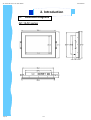
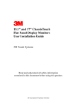
C.
Dimension Diagrams
AP-12AV series
Apr 05
P.3
AP-12AV/ DP-12AV / OP-12AV Series
User Manual
2. Introduction
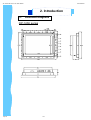
C.
Dimension Diagrams
DP-12AV series
Apr 05
P.4
AP-12AV/ DP-12AV / OP-12AV Series
User Manual
2. Introduction
C.
Dimension Diagrams
OP-12AV series
Apr 05
P.5
AP-12AV/ DP-12AV / OP-12AV Series
User Manual
2. Introduction
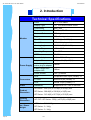
Technical Specifications
Monitor
Power Supply
Connectors
Video
Panel
12.1" LCD Panel
Display Type
TFT LCD active matrix colour
Resolutions
800 x 600
Response Time
Tr=20ms, Tf=35ms
Contrast Ratio
200:1 typical
Brightness
300 cd/m2 typical
Pixel Pitch
0.3075(H) x 0.3075(V)
Panel Colour
262,144 display colour
Viewing Angle
60/60/40/55 ( R/L/U/D )
Storage Temp.
-20° to 60°C
Operating Temp.
0° to 50°C
MTBF
50,000 hours
Remote Adapter
110V - 220V AC Input
Adapter Size
108(L) x 64 (W) x 30(H) mm
Cable Length from
mains plug to adapter
182cm
Cable Length from
adapter Unit
180cm
Power Socket
12V (+) female
RCA
Composite video input (female) x 1
S-Video
MiniDIN 4-pin (female) x 1
VGA
HDDB 15-pin (female) x 1
Standards
Supports NTSC, PAL or SECAM
AP Series : 326.5(W) x 270.4(H) x 58.3(D) mm
Product
Dimension
DP Series : 288.8(W) x 230.6(H) x 54(D) mm
OP Series : 315.4(W) x 257.2(H) x 52.3(D) mm
Packing
Dimension
AP / DP / OP Series : 555(L) x 470(W) x 90(D) mm
AP Series : 2.5 / 4.5 Kg
Net / Gross
Weight
DP Series : 2 / 4 Kg
OP Series : 2 / 4 Kg
Apr 05
P.6
AP-12AV/ DP-12AV / OP-12AV Series
User Manual
3. Installation
A.
Package Contents
After unpacking the carton, check and see if the following items are included in
good condition. Contact your supplier as soon as possible for replacing the
missing / damaged items.
●
12.1” TFT LCD monitor
●
VGA Cable (Male to Male)
●
DC 12V Adapter
●
Power Cord
●
Mounting Bracket (AP Series only)
●
User Manual
●
CD Disc
●
RCA Cable (For AV version only)
●
S-Video Cable (For AV version only)
D.
Caution to the user
To assure continued FCC compliance, please use grounded power supply
cord and the provided shielded video interface cable with bonded ferrite cores.
If a BNC cable is going to be used, use only a shielded BNC (5) cable. Also,
The Federal Communications Commission warns the user that any
unauthorized changes or modifications to the unit if not expressly approved by
the party responsible for compliance could void the user's authority of
operating the equipment.
E.
Cleaning
1. Gently wipe screen with a clean camel hair lens brush, or a soft, clean,
lint-free cloth. This removes dust and other particles that can scratch the
screen.
2. Do not apply excessive pressure to the screen surface when wiping it clean
because this may damage the LCD.
3. Do not pour or spray any liquid directly onto the screen or case of the LCD
monitor. Chemical cleaners have been reported to damage the screen or
case of the LCD monitor.
Apr 05
P.7
AP-12AV/ DP-12AV / OP-12AV Series
User Manual
3. Installation
F.
Precautions
Read all of these instructions and save them for later use. Follow all warnings
and instructions on the product.
Product
●
Do not cover or block the vent holes in the case.
●
Do not insert sharp objects or spill liquid into the LCD monitor through
cabinet slots. They may cause accident fire, electric shock or failure.
●
Disconnect the power plug from the AC outlet if you will not use it for an
indefinite period of time.
●
Do not attempt to service this product yourself, as opening or removing
covers may expose you to dangerous voltage points or other risks.
●
Do not touch the screen directly with your fingers. You may damage the
screen, and oil from your skin in difficult to move.
●
Do not apply pressure to screen. The LCD is very delicate.
Power
1. Use the type of power indicated on the marking label.
Plugs
1. Do not remove any of the prongs of the monitor’s three-pronged power
plug.
2. Disconnect the power plug from the AC outlet under following
conditions :
Apr 05
●
If the product will not be used for an indefinite period time.
●
When the power cord or plug is damaged or frayed.
●
If the product does not operate normally when the operating
instructions are followed.
●
Adjust only those controls that are covered by the operating
instructions.
Improper adjustment of other controls may result in
damage and will often require extensive work by a qualified
technician to restore the product to normal operation.
●
If the product has been dropped or the cabinet has been damaged.
●
If the product exhibits a distinct change in performance, indicating a
need for service.
P.8
AP-12AV/ DP-12AV / OP-12AV Series
User Manual
3. Installation
F.
Precautions (Cont.)
Power and extension cords
1. Do not allow anything to rest on the power cord.
2. Do not locate this product where persons will walk on the cord.
3. Use the proper power cord with correct attachment plug type. If the
power source is 120V AC, use a power cord that has UL and C-UL
approvals. If the power source is a 240V AC supply, use the tandem
(T blade) type attachment plug with ground conductor power cord that
meets the respective European country’s safety regulations, such as
VDE for Germany.
4. Do not overload wall outlets or power cords. Ensure that the total of all
units plugged into the wall outlet does not exceed 10 amperes.
5. Ensure that the total ampere ratings on all units plugged into the
extension cord is not above the cord’s rating.
6. If the power supply cord, which came with your monitor, is to be
connected to the PC instead of the wall outlet, this equipment is to be
used with UL/TÜV approved computers with receptacle rated
100~240V AC, 50/60Hz, 1.0A(minimum).
Environment
1. Place the monitor on a flat and leveled surface.
2. Place the monitor in a well-ventilated place.
3. Keep the monitor away from : Overly hot, cold or humid places, places
directly under sunlight, dusty surroundings, equipment that generate
strong magnetic fields.
Apr 05
P.9
AP-12AV/ DP-12AV / OP-12AV Series
User Manual
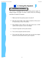
4. Using the System
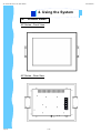
A.
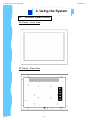
Product Views
AP Series - Front View
AP Series - Rear View
Apr 05
P.10
AP-12AV/ DP-12AV / OP-12AV Series
User Manual
4. Using the System
A.
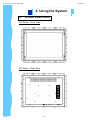
Product Views (Cont.)
DP Series - Front View
DP Series - Rear View
Apr 05
P.11
AP-12AV/ DP-12AV / OP-12AV Series
User Manual
4. Using the System
A.
Product Views (Cont.)
OP Series - Front View
OP Series - Rear View
Apr 05
P.12
AP-12AV/ DP-12AV / OP-12AV Series
User Manual
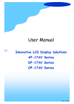
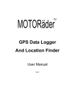
4. Using the System
B.
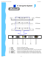
I/O Outlet
AP Series
DP Series
OP Series
(1)
1.
2.
3.
4.
5.
6.
Apr 05
DC IN
PC IN
RCA IN
S-Video IN
USB IN
SERIAL IN
(2)
(3)
(4)
(5)
(6)
: Connect to DC power cable.
: Connect to D-Sub 15 pin signal connector.
: Connect to the composite cable connector. (for AV series only)
: Connect to the S-Video cable connector. (for AV series only)
: Connect to the USB connector. (for Touchscreen series only)
: Connect to the Serial connector. (for Touchscreen series only)
P.13
AP-12AV/ DP-12AV / OP-12AV Series
User Manual
4. Using the System
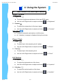
C.
Installation Procedures
This monitor is equipped with an auto-sensing power supply for
voltage ranges 100~240V, 50~60Hz. Please follow the following
instruction to install LCD monitor.
1. Make sure that the system power is turned off.
2. Plug the signal cable to the signal connector at the rear of
PC and the rear of the LCD monitor.
3. Plug adapter output cable to the jack at the rear of LCD
monitor and the power cord to the adapter.
4. Connect the power cord to power source.
5. Turn on the computer and the monitor.
6. Then push the OSD menu button and use the Auto Adjust
function to fine the best mode of your computer.
Apr 05
P.14
AP-12AV/ DP-12AV / OP-12AV Series
User Manual
4. Using the System
D.
Setup Touchscreen
Touchscreen used for UltraView products are manufactured by 3M. Here provide
TouchWareTM Software includes touch screen drivers for your installing.
Note: To configure the settings of the touchscreen, please refer to the
TouchWareTM User Guideline
Note: If you have a Microsoft® IntelliPoint® or Kensington® Mousework® PS/2
mouse, installing TouchWareTM software will disable the special mouse
functionally of these devices
For Windows 95, 98, Me, NT4.0, 2000 & XP
1.
Open the driver CD provided along with the product or download the driver
from our Website.
2.
Make sure you have completed the appropriate hardware connections.
3.
Power on your system. Make sure no other application are opened.
4.
Double click the “TW564SR4.exe” files.
5.
Unzip the file and save it in a default folder
Note: Remember the path of the default folder or create a new folder by your decision.
6.
Follow the onscreen instructions to begin the installation.
Note: Choose Express option for automatically installs the required TouchWareTM
software files, create a TouchWareTM software p r o g r a m f i l e s, a n d p l a c e a
TouchWare TM software icon on the Windows desktop and control panel.
TouchWareTM will also determine multiple monitor configurations at this time.
Note: For details of Custom option, please refer to the website of 3M and download the
user guide of TouchWareTM software.
(http:// www.3m.com/3MTouchSystems/downloads/tecdoc.jhtml)
Apr 05
P.15
AP-12AV/ DP-12AV / OP-12AV Series
User Manual
4. Using the System
D.
Setup Touchscreen
For Windows 95, 98, Me, NT4.0, 2000 & XP (Cont.)
7.
Once installation is complete, restart the system. As the system restarts,
Windows detects and loads the driver.
●
For serial controllers, restart the system. As the system restarts, Windows detects and load the driver
Note: This step is not necessary for Windows 2000 or above system, The driver loads
automatically.
●
For USB controllers, connect the touch screen cable to the USB port in
your computer. After a few seconds, the system beeps to indicate it has
detected the touch screen and loaded the driver.
For DOS
When you install Touchware from DOS, the Install program only loads the
touchscreen files specific to DOS. The installation includes the following files:
●
Touchscreen driver for DOS
●
Touchscreen control panel for DOS
●
Pen Configuration utility for DOS
●
Microcal Diagnostic utility
●
ThruGlass control panel for DOS
●
DOS help files
If you do not plan to use any of the touchscreen files for windows, you may want
to install just the DOS touchscreen files.
Apr 05
1.
Open the driver CD provided along with the product or download the driver
from our Website.
2.
Make sure you have completed the appropriate hardware connections. If
not, the Install program cannot properly configure the touchscreen.
3.
Close all applications and exit from Windows.
4.
Insert the TouchWare Disk into a diskette drive.
5.
Access the DOS command line prompt.
6.
Change to the drive that has the TouchWare diskette. For example, enter A:
if you inserted the TouchWare diskette in Drive A.
P.16
AP-12AV/ DP-12AV / OP-12AV Series
User Manual
4. Using the System
D.
Setup Touchscreen
For DOS (Cont.)
7.
Type INSTALL followed by the source disk drive, the destination drive, and
the destination directory.
For example, the following command copies the files from Drive A (source
drive) to Drive C (destination drive) and the \MTS\TOUCH directory :
INSTALL A: C:\MTS\TOUCH
8.
9.
Press Enter. The system reports that it is about to copy the DOS touchscreen
files and prompt for confirmation that you want to continue.
Press C to start the installation.
●
First, the Install program copies all DOS touchscreen files from the
TouchWare diskette to the specified destination drive and directory.
●
Next, the Install program automatically searched through the system
and configures the touchscreen to the proper COM port, interrupt, and
communication rate.
●
Finally, the Install program prompts if you want it to automatically modify
your AUTOEXEC.BAT file
If you let the Install program modify your AUTOEXEC.BAT file, the system
automatically loads the DOS touchscreen driver whenever you start your
computer.
If you do not let the Install program modify your AUTOEXEC.BAT file, you
must load the DOS touchscreen driver before using a DOS touch application.
For more information, refer to “Loading the DOS Touchscreen Driver” in the
next page
Apr 05
P.17
AP-12AV/ DP-12AV / OP-12AV Series
User Manual
4. Using the System
D.
Setup Touchscreen
For DOS (Cont.)
Loading the DOS Touchscreen Driver
After you install the files for the DOS touchscreen driver, you must load the driver
before you can run a DOS touch application or open the DOS Touchscreen
control panel.
You can run the DOS touchscreen driver from a full-screen DOS session within
Windows. However, the Windows touchscreen driver cannot be running. Error
message reads: “Windows x.x is running in 386 Enhanced mode. Device not
found.”
This means either the Windows Touchscreen driver is loaded or the COM port/
IRQ designations are incorrect.
You can manually load the DOS touchscreen driver when needed, or you can let
the system automatically load the driver when you start up your computer.
●
To manually load the DOS touchscreen driver:
1. Close all applications and exit from Windows.
2. Access the DOS command line prompt.
3. Use the Change Directory (cd) command to switch to the directory that
has the DOS touch driver files. By default, the Install program loads
TouchWare into the C:\MTS|TOUCH directory.
4. Type DOSTOUCH and then press Enter. The system displays a message
that the driver is now installed. For example:
MicroTouch Mouse Emulator - Version x.x
Copyright © 1990 - 1997 MicroTouch Systems, Inc.
Driver Installed
●
To automatically load the DOS touchscreen driver when you start up your
computer, add the following line to your AUTOEXEC.BAT file :
drive-designator :\directory\DOSTOUCH
where drive-designator and directory define the location (disk and path) of
the files for the DOS touchscreen. For example:
C:\MTS\TOUCH\DOSTOUCH
Apr 05
P.18
AP-12AV/ DP-12AV / OP-12AV Series
User Manual
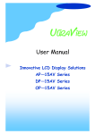
4. Using the System
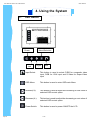
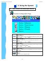
F.
OSD Switch
Power
Left
Apr 05
Menu/Selection
Right
Exit
Input Select:
This button is used to select CVBS for composite video
input, RGB for VGA input and S-Video for Super-Video
input
OSD Menu:
This button is used to enter OSD main Menu
Increase(à):
This button is used to adjust the increasing or next value of
selected OSD control option.
Decrease(ß):
This button is used to adjust the decreasing or next value of
selected OSD control option.
Power Switch:
This button is used to power ON/OFF the LCD
P.19
AP-12AV/ DP-12AV / OP-12AV Series
User Manual
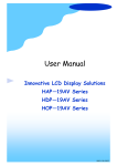
4. Using the System
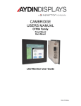
F.
OSD Control For VGA Input Version
LCD Membrane Diagram
Power
Menu/Selection
Left
Right
Exit
Main Menu
BRIGHT / CONTRAST
AUTO ADJUST
PHASE / CLOCK
H/V Position
MISC
RESET
Main Menu
Bright / Contrast
●
To enter into the Bright, Black level & Contrast sub-menu
Auto Adjust
●
To perform automatic optimisations of all functions
●
An “ Adjusting” message is displayed during the process
Phase / Clock
●
To enter into the phase & clock sub menu
H/V Position
●
To enter into the Position sub-menu
MISC
●
To enter into the MISC sub-menu
Reset
● Reset to the default factory settings
Apr 05
P.20
AP-12AV/ DP-12AV / OP-12AV Series
User Manual
4. Using the System
F.
OSD Control For VGA Input Version
Bright / Contrast
1. Brightness
●
To perform brightness adjustment of the input RGB signal
●
Use the Left & Right button to adjust and button
to “Brightness”
2. Contrast
●
To adjust the contrast level of the input signal
●
Use the Left & Right button to adjust and button
to “Contrast”
Auto Adjust
●
●
To perform automatic optimisations of all functions
An “ Adjusting” message is displayed during the process
Phase / Clock
1. Phase
●
To adjust input video sampling clock’s phase
●
Use the Left & Right button to adjust and button
to “Phase”
2. Clock
●
To adjust input video sampling clock
●
Use the Left & Right button to adjust and button
to “Clock”
H/V Position
1. H.Position
●
To adjust the horizontal size of the frame
●
Use the Left & Right button to adjust and button
to “H.position”.
2. V.Position
Apr 05
●
To adjust the vertical position of the frame
●
Use the Left & Right button to adjust and button
P.21
to “V.position”.
AP-12AV/ DP-12AV / OP-12AV Series
User Manual
4. Using the System
F.
OSD Control For VGA Input Version
MISC
1. Information
●
●
●
The first header row shows the current resolution setup
The second header row shows the horizontal frequency of the current
input signal
The third header row shows the vertical frequency of the current input
signal
2. OSD Timer
●
To modify the duration of the OSD time-out
3. Colour
a) 5500K
●
Select Colour Temp at 5500K
b) 6500K
●
Select Colour Temp at 6500K
c) 9500K
●
Select Colour Temp at 9500K
d) User
●
Change Colour Temp by manual
4. Language
● To select the language of OSD menu 7 Languages :
(1) English
(2) Japanese (日本語)
(3) Chinese (中文)
(4) German
(5) Francais
(6) Espanol
(7) Italiano
Apr 05
P.22
AP-12AV/ DP-12AV / OP-12AV Series
User Manual
4. Using the System
F.
G.
OSD Control For Video Input Version
Colour Configuration Page
Colour
Brightness
Contrast
Colour Adjust
Exit
Brightness ︰
Adjust the brightness value from 1 to 100 using (à)
and (ß) buttons.
Contrast ︰
Adjust the contrast value from 1 to 100 using (à) and
(ß) buttons.
Colour Adjust ︰
Select the colour temperature option for
9300K
or 6500K
or RGB
Exit ︰
Exit the Colour configuration Page
Apr 05
P.23
AP-12AV/ DP-12AV / OP-12AV Series
User Manual
4. Using the System
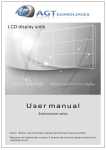
G.
OSD Control For Video Input Version
Picture Configuration Page
Picture
H.Position
V.Position
Sharpness
Phase
Clock
Exit
H.Position ︰
Press (à) shifting display image to right with value from 0 to 100;
Press (ß) shifting display image to left from value 0 to 100.
V.Position ︰
Press (à) shifting display image to upward with value from 0 to 100;
Press (ß) shifting display image to downward from value 0 to 100.
Sharpness ︰
Adjust the sharpness of the S-Video and CVBS image with 5 levels
Phase ︰
Adjust the phase of PPL clock by using (à) and (ß) buttons
Clock ︰
Adjust clock rate to improves colour display by using (à) and (ß)
buttons
Exit ︰
Exit the Picture configuration Page
Apr 05
P.24
AP-12AV/ DP-12AV / OP-12AV Series
User Manual
4. Using the System
G.
OSD Control For Video Input Version
Function Configuration Page
Function
Auto Adjust
Auto Position
Auto Phase
Auto Clock
Exit
Auto Adjust ︰
Enable or disable function for auto adjusting brightness, contrast, color etc.
Yes ︰ Enable
No ︰ Disable
Auto Position ︰
Enable or disable function for auto adjusting horizontal position or vertical
position
Yes ︰ Enable
No ︰ Disable
Auto Phase ︰
Enable or disable function for auto adjusting physical voltage to improves
focus, clarity and image stability
Yes ︰ Enable
No ︰ Disable
Auto Clock ︰
Enable or disable function for auto adjusting to clock rate to improves colour display.
Exit ︰
Exit the Function configuration Page
Apr 05
P.25
AP-12AV/ DP-12AV / OP-12AV Series
User Manual
4. Using the System
G.
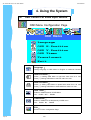
OSD Control For Video Input Version
OSD Menu Configuration Page
OSD Menu
Language
OSD H.Position
OSD V.Position
OSD Timer
Translucent
Exit
Language ︰
Change language of OSD Menu for English or traditional Chinese
OSD H.Position ︰
Press (") shifting OSD Menu to right with value from 0 to 100;
Press (!) shifting OSD Menu to left from value 0 to 100.
OSD V.Position ︰
Press (") shifting OSD Menu to upward with value from 0 to 100;
Press (!) shifting OSD Menu to downward from value 0 to 100.
OSD Timer ︰
Enable or disable timeout of OSD Menu
ON ︰ Enable OFF ︰ Disable
Translucent ︰
Enable or disable for the diaphaneity of OSD menu
Yes ︰ Enable No ︰ Disable
Exit ︰
Exit the Function configuration Page
Apr 05
P.26
AP-12AV/ DP-12AV / OP-12AV Series
User Manual
4. Using the System
G.
OSD Control For Video Input Version
Miscellaneous
Mode Select
Reset
Exit
Mode Select ︰
Switch the display size for 640 x 400 or 720 x 400 in DOS mode
Reset ︰
Enter for reloading all factory default
Exit ︰
Exit the Function configuration Page
Apr 05
P.27