1
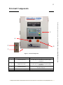
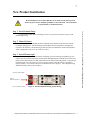
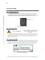
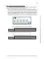
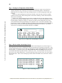
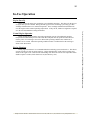
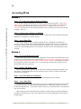
Catalyst Monitoring System User Manual
2
Hazard Warnings
For additional information or assistance contact 952-440-9200 or [email protected]
Do not attempt to work on unit while there is electrical current flowing to unit.
Ensure all power is off to eliminate possibility of electrical shock.
Electrical Shock Warning
To avoid risk of injury from electrical shock, all
work should be performed by a certified
electrician.
High Temperature Warning
To avoid risk of fire and burns , ensure all
flammable items are kept clear of area.
Phillips & Temro Industries • EM Products® Division • Prior Lake, MN 55372 • (952) 440-9200 • www.phillipsandtemro.com
3
Table of Contents
HAZARD WARNINGS ............................................................................................................................... 2
TABLE OF CONTENTS ............................................................................................................................. 3
KEY FUNCTIONS ....................................................................................................................................... 4
EXTERNAL COMPONENTS .................................................................................................................... 5
INTERNAL COMPONENTS ..................................................................................................................... 6
STEP 1.
STEP 2.
STEP 3.
STEP 4.
STEP 5.
INSTALL CONDUIT FITTING ............................................................................................................ 7
MOUNT ENCLOSURE ...................................................................................................................... 7
INSTALL THERMOCOUPLE .............................................................................................................. 7
INSTALL POWER CONNECTION ....................................................................................................... 8
INSTALL PRESSURE CONNECTIONS ................................................................................................ 9
SYSTEM STARTUP .................................................................................................................................. 10
STEP 1.
STEP 2.
STEP 3.
STEP 4.
STEP 5.
STEP 6.
STEP 7.
INSTALL SD MEMORY CARD ....................................................................................................... 10
POWERING ON SYSTEM ................................................................................................................ 10
SETTING TIME AND DATE ............................................................................................................ 10
SETTING DIFFERENTIAL PRESSURE WARNING AND ALARM ......................................................... 11
SETTING TEMPERATURE WARNINGS AND ALARMS .................ERROR! BOOKMARK NOT DEFINED.
SETTING LOW TEMPERATURE ALARM DISABLE ........................ERROR! BOOKMARK NOT DEFINED.
REVIEW ALARM ACKNOWLEDGE SCREEN ...................................................................................... 12
INFORMATION SCREENS ..................................................................................................................... 13
PROCESS SCREEN AND ALARM INDICATION ...........................................ERROR! BOOKMARK NOT DEFINED.
DIFFERENTIAL PRESSURE TREND............................................................................................................... 13
INLET TEMPERATURE TREND ..................................................................................................................... 14
IN-USE OPERATION ............................................................................................................................... 15
ENGINE START-UP .................................................................................................................................... 15
NORMAL ENGINE OPERATION ................................................................................................................... 15
ENGINE SHUTDOWN .................................................................................................................................. 15
ACCESSING DATA .................................................................................................................................. 16
STEP 1.
STEP 2.
STEP 3.
STEP 1.
STEP 2.
STEP 3.
STEP 4.
SET CONNECTED COMPUTERS ETHERNET SETTINGS ......................................................................
CONNECT YOUR COMPUTER VIA ETHERNET ..................................................................................
ACCESS DATA FILES ......................................................................................................................
POWER OFF MONITORING SYSTEM ..............................................................................................
REMOVE SD MEMORY CARD .......................................................................................................
INSERT INTO MEMORY CARD READER .........................................................................................
ACCESS DATA FILES ....................................................................................................................
16
16
16
16
16
16
16
WARRANTY INFORMATION ............................................................................................................... 17
Phillips & Temro Industries • EM Products® Division • Prior Lake, MN 55372 • (952) 440-9200 • www.phillipsandtemro.com
For additional information or assistance contact 952-440-9200 or [email protected]
NEW PRODUCT INSTALLATION .......................................................................................................... 7
4
For additional information or assistance contact 952-440-9200 or [email protected]
Key Functions
Scroll Right within
Screen
Scroll Left within
Screen
Scroll Up within
Screen
Scroll Down within
Screen
Tab Function
Delete Function
Escape Function
Enter Function
Help Function
Alarm Acknowledge
Function
Unassigned
Unassigned
Unassigned
Unassigned
Unassigned
Unassigned
Unassigned
Unassigned
Unassigned
Unassigned
Phillips & Temro Industries • EM Products® Division • Prior Lake, MN 55372 • (952) 440-9200 • www.phillipsandtemro.com
5
External Components
4
2
5
1
Figure 1. External Components
No.
Article Name
1
Low Pressure Port
2
High Pressure Port
3
Controller Interface
4
5
Alarm Indicator Light
Warning Indicator Light
Description
Connects to pressure tap downstream of catalyst.
Location may vary depending on pressure gauge
orientation.
Connects to pressure tap upstream of catalyst.
Location may vary depending on pressure gauge
orientation.
Analog and Digital XLE Operator Control Station, 3
inch Mono Display
Temperature and Differential Pressure Alarm Light
Temperature and Differential Pressure Warning Light
Phillips & Temro Industries • EM Products® Division • Prior Lake, MN 55372 • (952) 440-9200 • www.phillipsandtemro.com
For additional information or assistance contact 952-440-9200 or [email protected]
3
6
For additional information or assistance contact 952-440-9200 or [email protected]
Internal Components
1
2
3
4
5
6
10
7
8
9
Figure 2. Internal Components
No.
1
2
3
4
5
6
7
8
9
10
Article Name
PLC
Pressure Transmitter
Circuit Breaker
Surge Protector
Fuse
Controller Terminal Block
Thermocouple Terminal Block
Low Pressure Port
High Pressure Port
Relays
Description
Siemens S7 1211C
0-20 Inches H2O, 4-20 mA, Differential Pressure
120VAC, 10A, 1 Pole
120 VAC, Gas Tube
3A, Blown Fuse Indicator, Time Delay Glass
600V, 25A Rated
Type K Thermocouple
For Pressure Transmitter
For Pressure Transmitter
120 VAC, SPDT, 6A
Phillips & Temro Industries • EM Products® Division • Prior Lake, MN 55372 • (952) 440-9200 • www.phillipsandtemro.com
7
New Product Installation
Do not attempt to work on unit while there is electrical current flowing to unit.
Ensure all power is off to eliminate possibility of electrical shock. All work should
be performed by a certified electrician.
Use appropriate conduit knock-out fitting to create access point into enclosure for power and
thermocouple wiring.
Step 2. Mount Enclosure
Mounting brackets are included and can be installed on the backside of the enclosure with the
provided mounting points. The monitoring system should be protected from direct sun light and
exposure to the elements. The monitoring system must also be isolated from vibration and operated
within a temperature range of 32° to 122°F (0° to 50°C).
Step 3. Install Thermocouple
Install thermocouple connection into the monitoring system by inserting a stripped K type wire
into the open slot on the thermocouple terminal block and tightening the overhead screws until secure.
Polarity of the thermocouple wire and terminal block must match to function properly. In typical type
K thermocouple wires, the yellow wire refers to positive polarity while the red wire correlates to
negative polarity. For location of the power terminal block, refer to Figure 2. The completed wiring
should be similar to what is seen in Figure 3.
Negative Terminal (Red)
Type K
Thermocouple Wire
Positive Terminal (Yellow)
Figure 3. Thermocouple Monitoring System Wiring
Phillips & Temro Industries • EM Products® Division • Prior Lake, MN 55372 • (952) 440-9200 • www.phillipsandtemro.com
For additional information or assistance contact 952-440-9200 or [email protected]
Step 1. Install Conduit Fitting
8
With the top of the thermocouple removed, feed the thermocouple wire thru the side opening and
secure the positive and negative terminals using the internal screws. Each terminal is marked with the
appropriate polarity for which must be connected. The final wiring assembly should resemble Figure 4.
For additional information or assistance contact 952-440-9200 or [email protected]
Negative Terminal (Red)
Positive Terminal (Yellow)
Figure 4. Thermocouple Internal Wiring
Location of thermocouple port on catalyst housing can be seen in Figure 6. On smaller catalyst
housing models the thermocouple probe may contact the housing. It is recommended that the probe
end has at least 1/2" clearance from the catalyst housing wall. A 1/2" NPT pipe nipple is
recommended in these applications.
Step 4. Install Power Connection
Electrical Shock Warning
To avoid risk of injury from electrical shock, all
work should be performed by a certified
electrician.
Install power connection by inserting the stripped power wires into the L (Phase or Live) and N
(Neutral) slots on the power terminal block and tightening the overhead screws until secure. Live and
neutral wire positions are interchangeable with incoming AC current. The ground wire must be
installed into the grounding terminal and secured using the overhead screw. For location of the power
terminal block, refer to Figure 2. The completed wiring should be similar to what is seen in Figure 5.
Phillips & Temro Industries • EM Products® Division • Prior Lake, MN 55372 • (952) 440-9200 • www.phillipsandtemro.com
9
Ground Connection
Power Connection
Figure 5. Power Wiring
Step 5. Install Pressure Connections
High Temperature Warning
To avoid risk of fire and burns, ensure all
flammable items are kept clear of area.
Install the included compression tube fittings and 12" stainless steel tubing into the high and low
pressure ports on the catalyst housing. To allow for heat dissipation the included stainless steel tubing
must be installed. Additional piping from catalyst housing to monitoring system must be provided by
the user. The high pressure port on the sensor (labeled "high") must be connected to the pressure tap
upstream of the catalyst while the low pressure port (labeled "low") must be connected to the pressure
tap on the housing downstream of the catalyst. Locations of the pressure taps on a typical catalyst
housing are seen in Figure 1. 1/8" NPT is used on pressure sensor for port connections. Incorrect
installation of high and low pressure taps will result in a "++++" display for differential pressure.
Reversing the high and low pressure ports should yield a positive differential pressure reading.
Thermocouple Port
Flow Direction
Low Pressure Tap
High Pressure Tap
Figure 6. Catalyst Housing Port Locations
Phillips & Temro Industries • EM Products® Division • Prior Lake, MN 55372 • (952) 440-9200 • www.phillipsandtemro.com
For additional information or assistance contact 952-440-9200 or [email protected]
Power Connection
10
System Startup
For additional information or assistance contact 952-440-9200 or [email protected]
Step 1. Install SD Memory Card
To begin initial startup of the system, ensure the SD card is installed in the memory card slot
located behind the cover on the top side of the controller as seen in Figure 7. If the memory card is
not installed, insert the memory card into the slot by depressing the SD card until it is securely locked
into the controller. Without the memory card installed monitoring data will not be recorded.
SD Card Slot
Figure 7. SD Memory Card Install
Step 2. Powering On System
Electrical Shock Warning
To avoid risk of injury from electrical shock, all
work should be performed by a certified
electrician.
Power the system by putting the circuit breaker into the "ON" position. The external display will
turn on and the system will perform a self-test to ensure the system is functioning properly. Refer to
Figure 2 for circuit breaker location. In the case the system is not functioning properly contact a
Phillips & Temro representative.
Step 3. Setting Time and Date
Enter the time and date set screen by putting the cursor in the screen field located at the top and
scrolling to the “Date/Time” screen. To edit the time and date values move cursor to text box located
to the right of the “Set Time” button. Enter correct date and time in the exact format shown below.
Move cursor over to the “Set Time” button and hit the Green Enter button on the interface panel.
Figure 8. Date/Time Set Screen
Phillips & Temro Industries • EM Products® Division • Prior Lake, MN 55372 • (952) 440-9200 • www.phillipsandtemro.com
11
Step 4. Setting Warning and Alarm Setpoint Values
Figure 9. Differential Pressure Warning/Alarm Set Screen
Table 1. Recommended Differential Pressure Alarm Set Points
Warning
Alarm
Recommended Set Point for RICE NESHAP Compliance
Initial "Clean" Differential Pressure + 1 in-H2O
Initial "Clean" Differential Pressure + 2 in-H2O
Recommended high temperature values for RICE NESHAP compliance are seen in Table 2,
however catalyst capabilities must be considered to prevent failure of the catalyst.
Table 2. Recommended High Temperature Alarm Set Points
Warning
Alarm
Recommended Set Point for RICE NESHAP Compliance
1200 °F
1350 °F
*Catalyst capabilities must be considered when setting high temperature alarm set points
Phillips & Temro Industries • EM Products® Division • Prior Lake, MN 55372 • (952) 440-9200 • www.phillipsandtemro.com
For additional information or assistance contact 952-440-9200 or [email protected]
To specify warning and alarm values for the differential pressure across the catalyst unit
and inlet exhaust temperature, enter the set point screen seen in
Figure 9 by putting the cursor in the screen field located at the top and scrolling to the “Setpoints”
screen. You will be prompted to input a password. (Contact your Phillips & Temro representative for
the default password.) Within the set points screen the values for each are specified using the ENTER
and arrow functions. Put cursor in appropriate text box and enter values using the function keys and
then pressing enter. The steady state pressure drop from a "clean" catalyst must be accounted for
within the warning and alarm values. For example: if "clean" catalyst reading is at 5 in-H2O, the
warning and alarm values should be set at 6 and 7 in-H2O respectively. Recommended set values for
differential pressure warning and alarm to comply with RICE NESHAP regulations are seen in Table 1.
12
For additional information or assistance contact 952-440-9200 or [email protected]
Step 5. Setting Low Temperature Alarm Disable
As an additional feature the alarm lights can be disabled when the engine is shut off and is at
ambient temperature while continuing to record data on the monitoring system. The alarms are
disabled by one of two things: the low temp warning set point, or a motor running input wired to the
controller.
If there is a motor running status wired to the controller, set the low temp set point to 0 and the
controller will only look at motor running status as the means of alarming. Alarms will be disabled
when motor is not running.
If there is not a motor running status wired to the controller then the low temp warning set point
will need to be set to disable alarming under a “no run” condition. To specify the temperature at which
the alarm lights are disabled see Figure 10. Enter the set points screen by putting the cursor in the
screen field located at the top and scrolling to the “Setpoints” screen. You will be prompted to input
the password. (Contact your Phillips & Temro representative for the default password.) Within the set
points screen the values for each are specified using the ENTER and arrow functions. The default
value for the low temperature alarm disable should be set at 200 °F.
Figure 10. Low Temperature Alarm Disable Set Screen
Step 6. Review Alarm Acknowledge Screen
In addition to the Set Points screen there is an Alarm Acknowledge Screen, shown in Figure 11.
Upon startup the system will be in Warning and Alarm because there are no setpoints set in the PLC. Once
you have input setpoints in the previous steps you will need to go to the “Alarm Acknowledge” Screen and
clear the alarms. To navigate to this screen in Error! Reference source not found. put the cursor in the
screen field located at the top and scroll to the “Alarm Ack” screen. To clear the alarm, move the cursor
down to the “Ack” button and hit enter. To return to the home screen, move the cursor over to the “Home”
button and hit enter. There is also a running log of alarms which will indicate issues such as PLC Fault or
Com Loss.
Figure 11. Alarm Acknowledge Screen
Phillips & Temro Industries • EM Products® Division • Prior Lake, MN 55372 • (952) 440-9200 • www.phillipsandtemro.com
13
Information
Screens
Process Screen and Alarm Indication
The current differential pressure and inlet temperature readings can be viewed on the “Process”
Screen seen in Figure 12; this is also the Home screen upon startup. This screen also indicates Engine
Running status as well as the pressure and temperature alarm statuses.
*note – Alarms will be invisible under normal conditions.
High Temp
Warning
High Temp
Alarm
High Pressure
Warning
High Pressure
Alarm
Figure 12. Process Screen
Differential Pressure Trend
A real time plot of the differential pressure values being recorded can be seen by navigating to the
screen in Figure 13 by putting the cursor in the screen field located at the top and scroll to the “Press
Trend” screen. Differential pressure (in-H2O) is plotted on the y-axis while time is plotted on the xaxis allowing for real time trends to be seen. You can also view the current value to the right of the
graph. To return to the Home screen, put cursor on Home button and hit enter.
Figure 13. Differential Pressure Trend
Phillips & Temro Industries • EM Products® Division • Prior Lake, MN 55372 • (952) 440-9200 • www.phillipsandtemro.com
For additional information or assistance contact 952-440-9200 or [email protected]
Differential Pressure
Value
Inlet Temperature
Value
Engine Running
Status
14
Inlet Temperature Trend
For additional information or assistance contact 952-440-9200 or [email protected]
The recorded values for the inlet temperature are plotted in real time and can be seen by
navigating to the screen in Figure 14 by putting the cursor in the screen field located at the top and
scroll to the “Temp Trend” screen. Temperature (F) is plotted on the y-axis while time is plotted on
the x-axis. To return to the Home screen, put cursor on Home button and hit enter.
Figure 14. Inlet Temperature Trend
Phillips & Temro Industries • EM Products® Division • Prior Lake, MN 55372 • (952) 440-9200 • www.phillipsandtemro.com
15
In-Use Operation
Engine Start-Up
Normal Engine Operation
During normal engine operation, the catalyst monitoring system will continuously monitor
temperature and differential pressure and record data at the plot interval specified via the onboard
memory card. For a warning or error to be detected the operating condition must remain out of
tolerance for 10 seconds. When the operating condition returns to within tolerance the warning or
alarm will be deactivated.
Engine Shutdown
During engine shutdown it is recommended that the monitoring system remain active. This allows
accurate records to be kept of engine inactivity. Engine shutdown may result in false warnings and
alarms as the engine cools. These alarms and warnings will deactivate once the low temperature alarm
disable setpoint is reached, if this function is set (described on p.122).
Phillips & Temro Industries • EM Products® Division • Prior Lake, MN 55372 • (952) 440-9200 • www.phillipsandtemro.com
For additional information or assistance contact 952-440-9200 or [email protected]
Before starting the engine, the monitoring system should be turned on. This allows for the process
of engine start-up to be recorded. During the start-up process the monitoring system may give false
warnings and alarms due to low exhaust temperature. These warnings and alarms should deactivate
once the engine reaches normal operating temperatures. If they do not, further investigation is required
as to the reasons behind the warnings and alarms.
16
Accessing Data
Method 1
For additional information or assistance contact 952-440-9200 or [email protected]
Step 1. Set connected computers Ethernet Settings
Go into My computer and right click on network to open up network properties. Click change
adapter settings. Navigate to your computers LAN connection of your network card. Double click
your connection and when dialog box opens click on properties. Double click Internet Protocol
Version 4. Check the box Use the following IP address. Enter an IP on the same network as the PLC
(example – 10.10.0.3)
Step 2. Connect your computer via Ethernet
Disconnect the Ethernet cord that connects the PLC with the OIT screen on the front of the panel
and hook your computer up to the PLC directly.
Step 3. Access Data Files
Open Internet Explorer on your computer and type the PLC’s IP address in the address bar
(10.10.0.1). This will bring up the Controller Diagnostic Application where you can view data about
the controller and access the .CSV files being stored on the memory card. You have the choice of
viewing live or downloading the file to your computer. Data file will have the month and year as the
file name.
Method 2
Step 1. Power Off Monitoring System
Ensure power to the system is turned off by flipping the circuit breaker to the OFF position. Refer
to Figure 2 for circuit breaker location within enclosure. Not powering off system before removing the
memory card will result in a PLC Fault which will shut down the controller. This happens because the
PLC program is located on the memory card. To reset the fault you will need to cycle power to the
panel with the memory card inserted.
Step 2. Remove SD Memory Card
Remove the SD memory card from the top side of the controller by depressing the memory card.
The memory card should then slide out easily from the memory card slot. Location of the memory
card slot is seen in Figure 7.
Step 3. Insert Into Memory Card Reader
Insert the SD memory card into an appropriate media card reader on the computer.
Step 4. Access Data Files
The data files from the monitoring system are in a .CSV (Comma Separated Values) format which
can be opened using any text editor such as Notepad and Excel. Further data evaluation can also be
performed using these tools. A new data file will be created every month and will have the month and
year as the file name.
When completed, remove the SD card from computer and insert back into controller making sure
to push the card in until secure. The system can then be powered on by flipping the circuit breaker to
the ON position.
Phillips & Temro Industries • EM Products® Division • Prior Lake, MN 55372 • (952) 440-9200 • www.phillipsandtemro.com
17
Warranty Information
Phillips & Temro Industries products are guaranteed for one (1) year from date of purchase by the
consumer against defects due to materials and the Company’s workmanship only, as either and both of
which the Company shall be the sole judge.
Other defects or failures due to improper or careless installation, storage or handling, or usage
contract to manufacturer’s directions, design or specification, as to any and all of which the Company shall
be the sole judge, are specifically excluded from this guarantee.
No liability is accepted for return transportation charge, following repaid or replacement as
aforesaid or for reinstallation costs. No liability for loss or damage of any nature or kind, whether arising
out of or from the use of the produce, whether or not defective, is assumed. No other expressed or implied
warranties exist in the absence of special agreement.
Phillips & Temro Industries • EM Products® Division • Prior Lake, MN 55372 • (952) 440-9200 • www.phillipsandtemro.com
For additional information or assistance contact 952-440-9200 or [email protected]
The sole obligation hereunder shall be to repair, or at the Company’s option to replace products as
aforesaid, provided same are returned “Transportation Prepaid” to the Company’s nearest plant within the
said period.