1
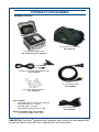
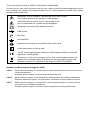
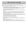
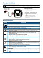
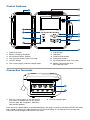
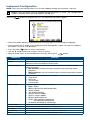
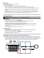
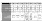
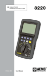
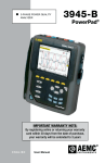
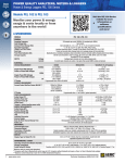
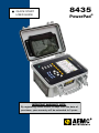
QUICK START USER GUIDE 8435 PowerPad® IMPORTANT WARRANTY NOTE: By registering online within 30 days from the date of purchase, your warranty will be extended to 3 years PRODUCT PACKAGING Shipping Contents: (1) Large Classic Tool Bag Cat. #2133.73 (1) PowerPad® Model 8435 Cat. #2136.41 or Cat. #2136.42 (5) Black Test Leads and Alligator Clips Cat. #2140.73 (1) 110V Power Cord Cat. #5000.63 (12) Color-coded ID Markers Cat. #2140.45 Also Included: • 4 GB USB Stick (DataView/User Manual) • 9.6V NiMh Battery - installed • 2 GB SD-Card - installed • High Voltage Warning/Caution Card (1) 5 ft USB Cable Cat. #2140.46 Kit (Cat. #2136.42 only) also includes: • (4) AmpFlex® Model A196-24-BK USB STICK: DataView® software and complete user manual for the Model 8435 can be located on the USB stick supplied with the instrument. Statement of Compliance Chauvin Arnoux®, Inc. d.b.a. AEMC® Instruments certifies that this instrument has been calibrated using standards and instruments traceable to international standards. We guarantee that at the time of shipping your instrument has met its published specifications. An NIST traceable certificate may be requested at the time of purchase, or obtained by returning the instrument to our repair and calibration facility, for a nominal charge. The recommended calibration interval for this instrument is 12 months and begins on the date of receipt by the customer. For recalibration, please use our calibration services. Refer to our repair and calibration section at www.aemc.com. Serial #: _________________________________ Catalog #:2136.41/2136.42 Model #: 8435 Please fill in the appropriate date as indicated: Date Received: __________________________________ Date Calibration Due: ________________________ Chauvin Arnoux®, Inc. d.b.a AEMC® Instruments www.aemc.com Thank you for purchasing an AEMC® PowerPad® III Model 8435 For best results from your instrument and for your safety, read the enclosed operating instructions carefully and comply with the precautions for use. These products must be only used by qualified and trained users. WARNING, risk of DANGER! The operator must refer to these instructions whenever this danger symbol appears. CAUTION! Risk of electric shock. The voltage at the parts marked with this symbol may be dangerous. Equipment is protected by double insulation. USB socket. SD Card. Ground/Earth. Important instructions to read and to fully understand. Useful information or hint to read. The CE marking guarantees conformity with European directives and with regulations covering EMC. The trash can with a line through it means that in the European Union, the product must undergo selective disposal for the recycling of electric and electronic material, in compliance with Directive WEEE 2002/96/EC. Definition of Measurement Categories (CAT) CAT IV Measurement category IV corresponds to measurements taken at the source of lowvoltage installations. Example: power feeders, counters and protection devices. CAT III Measurement category III corresponds to measurements on building installations. Example: distribution panel, circuit-breakers, machines or fixed industrial devices. CAT II Measurement category II corresponds to measurements taken on circuits directly connected to low-voltage installations. Example: power supply to domestic electrical appliances and portable tools. Precautions for Use This instrument and its accessories comply with safety standards IEC 61010-1, IEC 61010-031, and IEC 61010-2-032 for voltages of 600V in category IV or 1000V in category III. Failure to observe the safety instructions may result in electric shock, fire, explosion, and destruction of the instrument and of the installations. • The operator and/or the responsible authority must carefully read and clearly understand the various precautions to be taken in use. Sound knowledge and a keen awareness of electrical hazards are essential when using this instrument. • If you use this instrument other than as specified, the protection it provides may be compromised, thereby endangering you. • Do not use the instrument on networks of which the voltage or category exceeds those mentioned. • Do not use the instrument if it seems to be damaged, incomplete, or poorly closed. • Before each use, check the condition of the insulation on the leads, housing, and accessories. Any item of which the insulation is deteriorated (even partially) must be set aside for repair or scrapping. • Use only the leads and accessories supplied. Using leads (or accessories) of a lower voltage or category reduces the voltage or category of the combined instrument + leads (or accessories) to that of the leads (or accessories). • Use personal protection equipment systematically. • Keep your hands away from the terminals of the device. • When handling the leads, test probes, and alligator clips, keep your fingers behind the physical guard. • Use only the AC power adapter and battery pack supplied by the manufacturer. They include specific safety features. • Some current sensors must not be placed on or removed from bare conductors at hazardous voltages: refer to the sensor manual and comply with the handling instructions Charging the Battery Fully charge the battery before the first use. NOTE: A full recharge of a completely discharged battery takes approximately 5 hrs. 120V ± 10%, 60Hz 230V ± 10%, 50Hz To recharge the battery: • Unscrew the cover of the battery charging connector. • Connect the supplied power cord to the instrument and AC power. • The button lights and will go out when the power cord is disconnected. Button Functions BUTTON DESCRIPTION Return to the choice of measurement view. Configure the PowerPad® (SET-UP). Take a snapshot of the current screen or access screens already stored in the memory. Record associated waveform and power measurement data. Get help on the current display functions, in the language chosen by the user. Transients or Inrush Current: • Sets and views transient and inrush current waveforms associated with rapid changes in input Harmonics Mode: • Displays the harmonics in percent and value ratios for voltage, current and power for each harmonic through the 50th • Determines harmonic current produced by non-linear loads • Analyzes the problems caused by harmonics according to their order (heating of neutrals, conductors, motors, etc) Waveforms Mode: • Displays voltage and current waveforms or vector representation • Identifies signal distortion signatures • Displays of amplitude and phase unbalance for voltage and current • Checks connections for correct phase order Alarm Events: • Provides a list of the alarms recorded according to the thresholds programmed during configuration • Logs interruption with half-cycle resolution • Determines energy consumption exceedances • Stores value, duration, date, time and set point for up to 4096 events Trend Mode: • Lists all recording trends and views them on the display (Urms, Vrms, Arms, etc) Power / Energy: • Displays power levels and the associated parameters (power factor, displacement and tangent) • Energy monitoring • Four quadrant measurement to discern source/load active energy and inductive/capacitive reactive energy Control Features 6 1 7 8 2 3 9 10 4 11 ? 5 12 1. 2. 3. 4. 5. 6. 7. 8. 9. 10. 11. 12. Protective cover Battery charging connector Six function buttons (yellow) Four function buttons (see chart, left) ON/OFF button Four current inputs and five voltage inputs LCD Display USB port Confirm/Enter button Navigation buttons Six mode buttons (see chart, left) Battery compartment and SD-Card slot cover Connection Terminals L3/C N/D L2/B L1/A 1 2 N/D L3/C 1. Four (4) current inputs on the top of the instrument to enable the use of current sensors (MN, SR, AmpFlex®, MiniFlex®, J93 and MR probes). L2/B L1/A E/GN 2. Five (5) voltage inputs. Each terminal is protected by a weatherproof plug. The plugs must be removed to connect the leads, then stored in the pouch inside the front cover. Leave the plugs on unused terminals to keep the instrument water/air-tight and the terminals clean. Instrument Configuration NOTE: The instrument configurations can also be modified through the DataView® software. NOTE: The instrument must be configured the first time it is used. The configuration is saved in memory when the instrument is turned OFF. Press the button to configure the unit. The following sub-menus appear: • Press the yellow button corresponding to the language to set the display language. • The parameter that is ready to be configured will be highlighted in yellow. To move to a different parameter, use the ▲ and ▼ buttons. • Press the Enter button to select a parameter. • Use the ◄ and ► buttons to change a value or setting. • When finished, return to the Configuration menu by pressing the PARAMETER Date / Time Display Calculation Methods Electrical Connection Sensors & Ratios button. FUNCTION Sets the date and time format Adjusts the contrast and brightness of the display; Defines the color of the voltage and current curves Determines if harmonics are used or not used in calculations of reactive quantities (power and energy) • With harmonics: Harmonics are taken into account when calculating reactive parameters. • Without harmonics: Only the fundamental part is used for the calculation of reactive parameters Determines the type of connection to the network • Single-Phase • Split-Phase • 3-Phase 4-Wire • 3-Phase 5-Wire Defines the type of current probe to connect • • • • MN93: 200AAC MN193: 100A or 5AAC (with variable ratio) SR193: 1000AAC J93: 3500AAC/5000ADC • AmpFlex® Sensors: 6500AAC • MiniFlex® Sensors: 6500AAC • MR193: 1000A/1200A AC/DC • SL261: 100A (sensitivity 10mV/AAC/DC) 10A (sensitivity 100mV/AAC/DC) • 5A three-phase adapter (3-channel only) Transient Mode Trend (Recording) Mode Alarm Mode Erase Memory About Configures the voltage and current thresholds Selects the parameters to record (up to 4 configurations) Defines the parameters of an alarm Deletes configurations, alarm settings, snapshots and recordings Displays the serial number, software and hardware version SD-Card SD-Cards (up to 2GB only) are supported. To access the SD-Card: • Make sure that the instrument is disconnected and off. • Use a screwdriver to unscrew the 6 screws of the battery compartment cover. • Remove the cover and withdraw the battery from its compartment without disconnecting it. • Press on the SD-Card to release it then press on the protecting tab to withdraw it from its slot. • When replacing the SD-Card, the contacts must be on the left side, and the locator down. • Slide it into its slot until it snaps into place. The protecting tab is at the top of the card. • Put the battery back in its compartment and screw the cover back on. Getting Started NOTE: Make sure the PowerPad® is fully charged before use. Connecting: button. • Start the instrument by pressing the • Configure the instrument to obtain the required results and type of network. • Connect the current leads and sensors to the PowerPad®. • Connect the ground and/or neutral lead to the network ground and/or neutral (when distributed), as well as the corresponding current sensor. • Connect the L1 phase lead to the network L1 phase, as well as the corresponding current sensor. • Repeat the procedure for phases L2, L3 and N. Disconnecting: • Proceed in the reverse order to connecting, always finishing by disconnecting the ground and/or neutral (when distributed). button to turn the instrument off. • Disconnect the leads and press the • Recharge the battery, if necessary. Installation of the Leads and Current Sensors Color-coded ID markers are supplied with the PowerPad® to identify the leads and input terminals. • Detach the appropriate inserts from the color-coded marker and place them in the holes provided under the terminals (larger inserts for current terminals, smaller inserts for voltage terminals). • Clip the rings of the same color to the ends of the lead that will connect to the terminal. L3/C N/D N/D L3/C L2/B L2/B L1/A L1/A E/GN Installing DataView® DO NOT CONNECT THE INSTRUMENT TO THE PC BEFORE INSTALLING THE SOFTWARE AND DRIVERS. 1. Insert the USB stick into an available USB port (wait for driver to be installed). 2. If Autorun is enabled, an AutoPlay window should appear. If Autorun is disabled, it will be necessary to open Windows Explorer, then locate and open the USB stick drive labeled “DataView” to view the files on the drive. 3. In the AutoPlay window, select “Open folder to view files.” 4. Double-click on Setup.exe from the opened folder view to launch the Dataview® setup program. NOTE: For more information on using DataView®, refer to the Model 8435 user manual that is supplied on the USB stick. Updating Software & Firmware To provide our customers the best possible service in terms of performance and technical upgrades, AEMC® offers free software and firmware updates on our website. • Visit us at: www.aemc.com • Click on the TECH INFO tab, then click on the Software & Firmware Updates button. DataView® can also be updated by selecting “Update” from the Help menu within the software. WARNING: Updating the firmware will erase all stored data in the instrument. It is recommended to download all stored data before performing any firmware updates. IMPORTANT WARRANTY NOTE: By registering online within 30 days from the date of purchase, your warranty will be extended to 3 years Repair and Calibration To ensure that your instrument meets factory specifications, we recommend that it be scheduled back to our factory Service Center at one-year intervals for recalibration, or as required by other standards or internal procedures. For instrument repair and calibration: You must contact our Service Center for a Customer Service Authorization Number (CSA#). This will ensure that when your instrument arrives, it will be tracked and processed promptly. Please write the CSA# on the outside of the shipping container. If the instrument is returned for calibration, we need to know if you want a standard calibration, or a calibration traceable to N.I.S.T. (Includes calibration certificate plus recorded calibration data). Ship To: Chauvin Arnoux®, Inc. d.b.a. AEMC® Instruments 15 Faraday Drive • Dover, NH 03820 USA Phone: (800) 945-2362 or (603) 749-6434 (Ext. 360) Fax: (603) 742-2346 or (603) 749-6309 E-mail: [email protected] NOTE: You must obtain a CSA# before returning any instrument. Technical and Sales Assistance If you are experiencing any technical problems, or require any assistance with the proper operation or application of your instrument, please call, fax or e-mail our technical support team: Chauvin Arnoux®, Inc. d.b.a. AEMC® Instruments Phone: (800) 343-1391 or (508) 698-2115 (Ext. 351) Fax: (508) 698-2118 E-mail: [email protected] Limited Warranty The Model 8435 is warranted to the owner for a period of one year from the date of original purchase against defects in manufacture. This limited warranty is given by AEMC® Instruments, not by the distributor from whom it was purchased. This warranty is void if the unit has been tampered with, abused or if the defect is related to service not performed by AEMC® Instruments. Full warranty coverage and registration is available on our website: www.aemc.com/warranty.html. Please print the online Warranty Coverage Information for your records. What AEMC® Instruments will do: If a malfunction occurs within the warranty period, you may return the instrument to us for repair, provided we have your warranty registration on file or a proof of purchase. AEMC® Instruments will, at its option, repair or replace the faulty material. Warranty Repairs What you must do to return an Instrument for Warranty Repair: First, request a Customer Service Authorization Number (CSA#) by phone or e-mail from our Service Department, then return the instrument along with the signed CSA Form. Please write the CSA# on the outside of the shipping container. Return the instrument, shipment pre-paid to: Ship To: Chauvin Arnoux®, Inc. d.b.a. AEMC® Instruments 15 Faraday Drive • Dover, NH 03820 USA Phone: (800) 945-2362 or (603) 749-6434 (Ext. 360) E-mail:[email protected] Caution: To protect yourself against in-transit loss, we recommend you insure your returned material. NOTE: You must obtain a CSA# before returning any instrument. 11/14 99-MAN 100390 v2 Chauvin Arnoux®, Inc. d.b.a. AEMC® Instruments 15 Faraday Drive • Dover, NH 03820 USA • Phone: (603) 749-6434 • Fax: (603) 742-2346 www.aemc.com