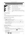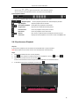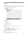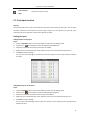
1
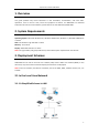
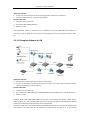
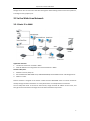
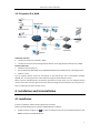
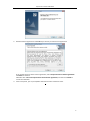
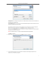
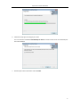
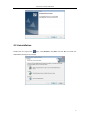
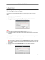
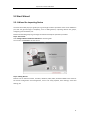
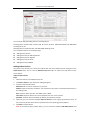
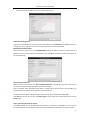
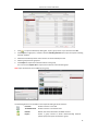
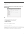
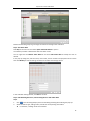
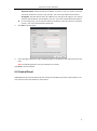
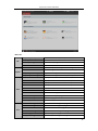
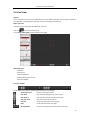
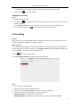
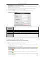
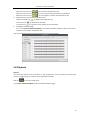
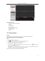
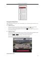
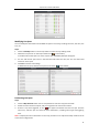
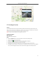
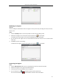
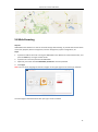
iVMS-4200 Client Software Quick Start Guide UD.6L0202B1538A01 Quick Start Guide of iVMS-4200 Thank you for purchasing our product. If there is any question or request, please do not hesitate to contact the dealer. This manual applies to iVMS-4200. This manual may contain several technically inaccurate points or printing errors, and the content is subject to change without notice. The updates will be added into the new version of this manual. We will readily improve or update the products or procedures described in the manual. 1 Quick Start Guide of iVMS-4200 1. Overview This guide provides only brief instructions on the installation, uninstallation, and some basic operations such as the live view, record and playback of devices via iVMS-4200. For detailed information of how to use the software, please refer to the User Manual of iVMS-4200. 2. System Requirements Operating System: Microsoft Windows XP / Windows 2003 32-bit, Windows 7 / Windows 2008 32-bit or 64-bit CPU: Intel Pentium IV @ 3.00 GHz or above Memory: 1G or above Display: 1024*768 resolution or above Note: For high stability and good performance, these above system requirements must be met. 3. Deployment Schemes iVMS-4200 can be used in the local area network (LAN) and the wide area network (WAN). In this document, only some of the connection deployment schemes are displayed. Note: In the real situation, the devices connected, such as the DVRs, NVRs, network cameras, etc., are scalable. 3.1 In the Local Area Network 3.1.1 A Simplified Scheme in LAN 2 Quick Start Guide of iVMS-4200 Application Scenario: 1. Only one or small quantities of clients need to get video stream from the devices. 2. The client and devices are in the same local subnet. Hardware Required: 1. Network cameras, DVRs, etc. 2. PC installed with iVMS-4200 client. 3. Switch or router. This deployment scheme is convenient and cost-effective. Only the iVMS-4200 client software is required and you can get direct access to the connected devices, such as the network cameras, DVRs, etc. 3.1.2 A Complete Scheme in LAN Application Scenario: 1. Multiple clients need to get video stream from the devices. 2. There is no hard disk on the device side or there are disks on the device side, but the record files need to be backed up for extra insurance. Hardware Required: 1. Network cameras, DVRs, etc. 2. PCs installed with iVMS-4200 client, iVMS-4200 PCNVR, Stream Media Server and Storage Server. 3. Switch or router. The DVR, HDVR, NVR, iVMS-4200 PCNVR can connect to and manage the cameras, speed domes, video encoders, etc., and the iVMS-4200 client can be used to manage the DVR, HDVR, NVR, PCNVR which provide relatively complete function of the management. The stream media server can be adopted to forward the video stream so as to lower the network load of the devices. The record files can be stored on the HDDs of the local device, or on the remote 3 Quick Start Guide of iVMS-4200 storage server. You can also access the client through the web browsing and do some basic operations, including live view, playback, etc. 3.2 In the Wide Area Network 3.2.1 Static IP in WAN Application Scenario: 1. The devices need to be accessed in WAN. 2. Static IP addresses are assigned to the connected devices in WAN. Hardware Required: 1. Network cameras, DVRs, etc. 2. PCs installed with iVMS-4200 client, iVMS-4200 PCNVR, Stream Media Server and Storage Server. 3. Switch or router. Static IP address is assigned to the device in WAN and the iVMS-4200 client can access the device directly through the static IP address. It is costly when there are multiple devices connected. You can adopt the router to connect to the Internet, assign the static IP address to the router, and then get access to the devices through the router static IP address and port No.. 4 Quick Start Guide of iVMS-4200 3.2.2 Dynamic IP in WAN Application Scenario: 1. The devices need to be accessed in WAN. 2. The devices can be accessed through device domain names (registered on DNS Server) in WAN. Hardware Required: 1. Network cameras, DVRs, etc. 2. PCs installed with iVMS-4200 client, iVMS-4200 PCNVR, Stream Media Server and Storage Server. 3. Switch or router. You can register domain names for the devices on the DNS server, such as Peanuthull, DynDNS, HiDDNS, etc., and then get access to the devices through the device domain names. When there are multiple devices connected to the Internet via the router, you can configure domain name on the router, and then get access to the devices through the router domain name and port No., thus to reduce the cost of the domain name. 4. Installation and Uninstallation 4.1 Installation Insert the installation media into the appropriate computer. Perform the following steps to install the iVMS-4200 client software. 1. Double-click the program file to enter the welcome panel of the InstallShield Wizard. Click Next to start the InstallShield Wizard. 5 Quick Start Guide of iVMS-4200 2. Read the License Agreement. Click Print if you want to print the license agreement. 3. If you accept the terms of the license agreement, click I accept the terms of license agreement. Click Next to continue. Otherwise click I do not accept the terms of the license agreement, and then click Cancel to cancel the installation On the next panel, you are prompted to select the function module to install. 6 Quick Start Guide of iVMS-4200 Storage Server: The storage server performs as a NVR installed on the PC and the record files can be stored on the storage server. Stream Media Server: The video stream can be forwarded through the stream media server, thus to lower the network load of the device. Set installation directory where the client software is to be installed. You can either accept the default directory that is displayed, or click Browse and select a different directory. You can also click Disk Space to choose the disk drive to install the software, and check the space information of the disk on the panel. Note: The default directory is C:\Program Files\iVMS-4200 Station\iVMS-4200. Click Next to continue. 4. Read the pre-install information and click Install to begin the installation. 5. A panel indicating progress of the installation is displayed. A percentage completion bar is updated as the installation progresses. 7 Quick Start Guide of iVMS-4200 6. Select the setup type according to your need. You can check the checkbox Create Desktop for Client to create a shortcut icon on the desktop for the client software. 7. Read the post-install information and click Finish. 8 Quick Start Guide of iVMS-4200 4.2 Uninstallation Double-click the program file again, select Remove, click Next and click Yes to uninstall the iVMS-4200 according to the prompts. 9 Quick Start Guide of iVMS-4200 5. Quick Start 5.1 User Registration and Login For the first time to use iVMS-4200 client software, you need to register a super user for login. Steps: 1. Input the super user name and password. 2. Confirm the password. 3. Optionally, check the checkbox Enable Auto-login to log in the software automatically. 4. Click Register. Then, you can log in the software as the super user. Notes: A user name cannot contain any of the following characters: / \ : * ? “ < > | The password cannot be empty and the length of the password should be no less than six characters. When opening iVMS-4200 after registration, you can log in the client software with the registered user name and password. Steps: 1. Input the user name and password you registered. Note: If you forget your password, please click Forgot Password and remember the encrypted string in the pop-up window. Contact your dealer and send the encrypted string to him to reset your password. 2. Optionally, check the checkbox Enable Auto-login to log in the software automatically. 3. Click Login. 10 Quick Start Guide of iVMS-4200 5.2 Start Wizard 5.2.1 Wizard for Importing Device The start wizard will pop up to guide you to go through the basic operations of the client software if you have not gone through it completely, such as adding devices, importing devices into groups, configuring record schedule, etc. Perform the following steps to go through the wizard and study the operations provided. Step 1: Start Guide Click Configure Device and Record Schedule to start the guide. You can also click Closed to exit the wizard. Step 2: Adding Devices Devices such as network cameras, encoders, decoders, DVRs, NVRs, should be added to the client for the remote configuration and management, such as live view, playback, alarm settings, video wall settings, etc. 11 Quick Start Guide of iVMS-4200 You can select adding encoding device or decoding device. Encoding device includes DVR, encoder, NVR, IP camera, IP dome, iVMS-4200 PCNVR and iVMS-4200 encoding server, etc. Decoding device includes decoder and iVMS-4200 decoding server. You can add the device in the following ways: Adding Online Devices Adding Devices by IP Address/Domain Adding Devices by IP Segment Adding Devices by IP Server Adding Devices by HiDDNS Adding Online Devices The active online devices in the same local subnet with the client software will be displayed on the Online Device area. You can click the Refresh Every 15s button to refresh the information of the online devices. Add One Online Device Steps: 1. Select the devices to be added from the list. 2. Click Add to Client to open the device adding dialog box. 3. Input the required information. Nickname: Edit a name for the device as you want. Address: Input the device’s IP address. The IP address of the device is obtained automatically in this adding mode. Port: Input the device port No.. The default value is 8000. User Name: Input the device user name. By default, the user name is admin. Password: Input the device password. By default, the password is 12345. 4. Optionally, you can check the checkbox Export to Group to create a group by the device name. All the cameras under the device will be imported to the corresponding group by default. 5. Click Add to add the device. Note: If you want to add an offline device, you can check the checkbox Add Offline Device and 12 Quick Start Guide of iVMS-4200 enter the number of cameras and alarm inputs of the device. Add All the Online Devices If you want to add all the online devices to the client software, click Add All and click OK in the pop-up message box. Then enter the user name and password for the devices to be added. Modify Network Information Select the device from the list, click Modify Netinfo, edit its IP address, port No., subnet mask and gateway, input the admin password of the device and click OK to modify the network information of the selected device. Restore Default Password Select the device from the list, click Restore Default Password, input the security code, and then you can restore the default admin password of the selected device. Note: The default admin password of the device is 12345, and the security code is returned after you send the data and serial No. of the device to the manufacturer. For details of other device adding methods, please refer to the User Manual of iVMS-4200. Click Next to continue. You can also click Home Page to return to the home page of the wizard, or click Finish to exit. Step 3: Importing Devices into Groups The added devices need to be organized into groups for a convenient management. You can get the live view, play back the record files, and do some other operations of the devices through the group. 13 Quick Start Guide of iVMS-4200 1. Click to open the Add Group dialog box, input a group name as you want and click OK. 2. Click Import on right panel, and then click the Encoding Channel tab to open the Import Encoding Channel interface. 3. Select the thumbnails/names of the cameras in the thumbnail/list view. 4. Select a group from the group list. 5. Click Import to import the selected cameras to the group. You can also click Import All to import all the cameras to the selected group. Note: Up to 64 cameras can be added to one group. The following buttons are available on the Import Encoding Channel interface: List View View the camera in list view. Thumbnail View View the camera in thumbnail view. Refresh Refresh the latest information of added cameras. Import Create a group named as device name-Encoding Channel (Alarm Input) and import the device to group. 14 Quick Start Guide of iVMS-4200 Collapse/Expand Collapse/Expand the thumbnails of cameras. Click Next to continue. Step 4: Configuring the Record Schedule The video files can be recorded on the HDDs, Net HDDs, SD/SDHC cards on the local device, or the storage server connected. Steps: 1. Select the camera from the Camera Group list. 2. Check the checkbox Record Schedule to enable device local recording. 3. Select the record schedule template from the drop-down list. 4. Click Advanced Settings to set the recording parameters. 5. Optionally, click Copy to… to copy the record schedule settings to other cameras. 6. Click Save to save the settings. Step 5: Wizard finished. The wizard is complete. Click Finish to close the wizard. 5.2.2 Wizard for Video Wall The wizard for video wall settings will pop up if you have not gone through it completely. You can also The iVMS-4200 software provides video wall wizard to guide you to go through the basic operations of video wall settings, such as adding decoding devices, linking output with video wall, etc. 15 Quick Start Guide of iVMS-4200 Perform the following steps to go through the wizard and configure the video wall. Step 1: Edit Video Wall Click Help in the menu bar and select Open Video Wall Wizard to open it. The software provides a default video wall view which is 3X3. You can right-click the Default Video Wall tab and select Edit Video Wall to modify the view as desired. In the pop-up dialog box, edit the name, row number, column number and proportion for the video wall. Click Modify to save the settings and back to the video wall settings wizard. In the video wall settings wizard, click Next to continue. Step 2: Add Decoding Resource, Link Decoding Resource with Video Wall Steps: 1. Click 2. Select the device type, adding mode, and edit the corresponding information. in the Decoding Output panel and the adding decoding device dialog box pops up. For decoder, 2 adding modes are selectable. 16 Quick Start Guide of iVMS-4200 IP/Domain Name: Add the device by IP address or Domain name. You need to enter the nickname, IP address or domain name, port No., user name and password of the device. IP Segment: Add the devices whose IP addresses are among the IP segment. You need to enter the start IP address, end IP address, port No., user name and password of the devices. For cascading server, you can add the device by IP address. Enter the nickname, IP address, port No., user name and password of the device. 3. Click Add to add the device. 4. In the decoding output area, drag a decoding output or the device to the video wall view to link them. Note: The decoding output can only be related to one monitor. Click Done to finish the wizard. 5.3 Control Panel iVMS-4200 provides user-friendly GUI for the convenient and effective operation of the software. The main control panel of the software is shown below: 17 Quick Start Guide of iVMS-4200 Menu Bar: Open Captured picture File System View Open Video File Open Log File Search and view the video files recorded on local PC. View the backup log files. Exit Exit the iVMS-4200 client software. Lock Lock screen operations. Log in the client again to unlock. Switch User Switch the login user. Import System Config File Import client configuration file from your computer. Export System Config File Export client configuration file to your computer. 1024*768 Display the window at size of 1024*768 pixels. 1280*1024 Display the window at size of 1280*1024 pixels. 1440*900 Display the window at size of 1440*900 pixels. 1680*1050 Display the window at size of 1680*1050 pixels. Full Screen Display the window in full screen. Control Panel Main View Remote Playback E-map Auxiliary Screen Preview Tool Search and view the captured pictures stored on local PC. Enter Control Panel interface. Open Main View page. Open Remote Playback page. Open E-map page. Open Auxiliary Screen Preview window. Device Management Open the Device Management page. Event Management Open the Event Management page. Record Schedule Account Management Log Search System Configuration Open the Record Schedule page. Open the Account Management page. Open the Log Search page. Open the System Configuration page. 18 Quick Start Guide of iVMS-4200 Broadcast Device Arming Control I/O Control Player Message Queue Open Wizard Open Video Wall Wizard Help User Manual (F1) About Language Select camera to start broadcasting. Set the arming status of devices. Turn on/off the alarm output. Open the player to play the video files. Display the information of Email message to be sent. Open the guide for the client configuration. Open the guide for the video wall configuration. Click to open the User Manual; you can also open the User Manual by pressing F1 on your keyboard. View the basic information of the client software. Select the language for the client software and reboot the software to activate the settings. The iVMS-4200 client software is composed of the following function modules: The Main View module provides live view of network cameras and video encoders, and supports some basic operations, such as picture capturing, recording, PTZ control, etc. The Remote Playback module provides the search, playback, export of record files. The Video Wall module provides the management of decoding device and video wall and the function of displaying the decoded video on video wall. The E-map module provides the displaying and management of E-maps, alarm inputs, hot regions and hot spots. The Device Management module provides the adding, modifying and deleting of different devices and the devices can be imported into groups for management. The Event Management module provides the settings of arming schedule, alarm linkage actions and other parameters for different events. The Record Schedule module provides the schedule settings for recording. The Account Management module provides the adding, modifying and deleting of user accounts and different permissions can be assigned for different users. The Log Search module provides the query of system log files and the log files can be filtered by different types. The System Configuration module provides the configuration of general parameters, file saving paths, alarm sounds and other system settings. Note: The Video Wall module only displays when decoding devices are added to the client. The function modules are easily accessed by clicking the navigation buttons on the control panel or by selecting the function module from the View or Tool menu. You can check the information, including current user, network usage, CPU usage, memory usage and time, in the upper-right corner of the main page. 19 Quick Start Guide of iVMS-4200 5.4 Live View Purpose: You can view the live video of the added cameras on the Main View page. And some basic operations are supported, including picture capturing, manual recording, PTZ control, etc. Before you start: A camera group is required to be defined for live view. Click the icon on the control panel, or click View->Main View to open the Main View page. Main View Page 1 View List 2 Camera List 3 PTZ Control Panel 4 Display Window of Live View 5 Live View Toolbar Live View Toolbar: On the Main View page, the following toolbar buttons are available: Set Screen Layout Set the screen layout mode. Save View Save the new settings for the current view. Save View as Save the current view as another new view. Stop Live View Stop the live view of all cameras. Previous Go for live view of the previous page. Next Go for live view of the next page. Resume/Pause Click to resume/pause the auto-switch in live view. 20 Quick Start Guide of iVMS-4200 Auto-switch Show /Hide the Menu Show/Hide the menu of auto-switch. Click again to hide. Mute/Audio On Turn off/on the audio in live view Full Screen Display the live view in full screen mode. Press ESC to exit. Starting Live View for One Camera Steps: 1. Open the Main View page. 2. 3. Optionally, click the icon in live view toolbar to select the screen layout mode for live view. Click-and-drag the camera to the display window, or double-click the camera name after selecting the display window to start the live view. Note: You can click-and-drag the video of the camera in live view to another display window if needed. Starting Live View for Camera Group Steps: 1. Open the Main View page. 2. Click-and-drag the group to the display window, or double-click the group name to start the live view. Note: The display window number is self-adaptive to the camera number of the group. Starting Live View in Default View Mode Purpose: The video of the added cameras can be displayed in different view modes. 4 frequently-used default view modes are selectable: 1-Screen, 4-Screen, 9-Screen and 16-Screen. Steps: 1. Open the Main View page. 2. Click the icon 3. Click to select the default view mode, and the video of the added cameras will be displayed in a to expand the default view list. sequence in the selected view. Note: Right-click the current default view name on the list and click Save View As., and you can save the default view as a custom view. Starting Live View in Custom View Mode Purpose: The view mode can also be customized for the video live view. Steps: 1. Open the Main View page. 2. Click the icon 3. Click New View in the custom view list to create a new view. 4. Input the view name and click Add. The new view is of 4-Screen mode by default. to expand the custom view list. Optionally, click the view. 5. icon in live view toolbar and select the screen layout mode for the new Click-and-drag the camera/group to the display window, 21 Quick Start Guide of iVMS-4200 or double-click the camera/group name in custom view mode to start the live view. 6. Click the icon to save the new view. Stopping the Live View Steps: 1. Select the display window. 2. Click the icon display window, that appears in the upper-right corner when the mouse pointer is over the or click Stop Live View on the right-click menu to stop the live view of the display window. You can also click the button in live view toolbar to stop all the live view. 5.5 Recording Purpose: Some local devices, including the DVRs, NVRs, and Network Cameras, provide storage devices such as the HDDs, Net HDDs and SD/SDHC cards for record files. Before you start: The newly installed storage devices need to be formatted. In the Device Management page, enter the remote configuration interface of the device, click Storage->General, select the HDD or SD/SDHC card, and click Format to initialize the selected storage device. Click the icon on the control panel, or click Tool->Record Schedule to open the Record Schedule page. Steps: 1. Open the Record Schedule page. 2. Select the camera from the Camera Group list. 3. Check the checkbox Record Schedule to enable device local recording. 4. Select the record schedule template from the drop-down list. All-day Template: for all-day continuous recording. Weekday Template: for working-hours continuous recording from 8:00 AM to 8:00 PM. 22 Quick Start Guide of iVMS-4200 Event Template: for the event triggered recording. Template 01-08: fixed templates for specific schedules. You can edit the templates if needed. Custom: can be customized as desired. If you need to edit or customize the template, see Configuring Record Schedule Template. 5. Click Advanced Settings to set the recording parameters. 6. Optionally, click Copy to… to copy the record schedule settings to other cameras. 7. Click Save to save the settings. Parameters Pre-record Post-record Video Expired Time Redundant Record Descriptions Normally used for the event triggered record, when you want to record before the event happens After the event finished, the video can also be recorded for a certain time. The time for keeping the record files in the storage device, once exceeded, the files will be deleted. The files will be saved permanently if the value is set as 0. Save the video files not only in the R/W HDD but also in the redundant HDD. Record Audio Record the video files with audio or not. Video Stream Select the stream type for the recording. Configuring Record Schedule Template Perform the following steps to configure the record schedule template: If Template 01-08 is selected from the drop-down list, start from step 1; If Custom is selected from the drop-down list, start from step 2. 1. Click Edit to enter the Templates Management interface. Select the template to be set and you can edit the template name. 2. Set the time schedule for the selected template. refer to normal schedule record. The schedule time bar is marked with marked with refers to the schedule record triggered by the event. The schedule time bar is . marked with refers to the schedule record triggered by command. The schedule time bar is . . Note: Record triggered by command is only available for the ATM transactions when the ATM DVR is added to iVMS-4200. 23 Quick Start Guide of iVMS-4200 3. When the cursor turns to , you can edit the schedule time bar. When the cursor turns to , you can move the selected time bar you just edited. When the cursor turns to , you can lengthen or shorten the selected time bar. Optionally, you can select the schedule time bar, and then click the icon or click the icon or click the icon 4. to delete the selected time bar, to delete all the time bars, to copy the time bar settings to the other dates. Click OK to save the settings. You can click Save as Schedule Template on the Custom Schedule interface, and then the custom template can be saved as template 01--08. Note: Up to 8 time periods can be set for each day in the record schedule. 5.6 Playback Purpose: The record files stored on the local device or the storage server can be searched by custom view, camera or triggering event, and then can be played back remotely. Click the icon on the control panel, or click View->Remote Playback to open the Remote Playback page. 24 Quick Start Guide of iVMS-4200 Remote Playback Page 1 View List, Camera List and Event List 2 Calendar 3 Search Options 4 Search Result List 5 Display Window of Playback 6 Playback Toolbar 7 Timeline 5.6.1 Normal Playback Purpose: The record files can be searched by custom view or camera for the Normal Playback. Searching Record Files for Normal Playback Steps: 1. Open the Remote Playback page. 2. Click 3. Select the view or camera to be searched from the list. 4. Select the day to be searched on the calendar. to expand the View List or Camera List on the left-side. You can also click to show more search options, and then click the icon start time and end time for the search. 5. to specify the Click Search. The record files of the selected view or camera will be displayed on the Search Result list. You can filter the results through the Filter text field. Note: Up to 16 cameras can be searched simultaneously. 25 Quick Start Guide of iVMS-4200 Playing Back Record Files After searching the record files for the normal playback, you can play back the record files in the following two ways: Playback by File List Select the record file from the search result list, and then click the icon on the record file, or double-click the record file to play the video on the display window of playback. You can also select a display window and click the icon corresponding record file. in the toolbar to play back the Playback by Timeline The timeline indicates the time duration for the record file, and the record files of different types are color coded. Click on the timeline to play back the video of the specific time. You can click or to scale up or scale down the timeline bar. You can click or to go to the previous or the next time period. You can use the mouse wheel to zoom in or zoom out on the timeline. Normal Playback Toolbar: 26 Quick Start Guide of iVMS-4200 On the Normal Playback page, the following toolbar buttons are available: Playback Speed Set the playback speed for the selected display window. Async/Sync Click Playback synchronously/asynchronously. Stop Playback Stop the playback of all cameras. Pause/Start to play back the record files Pause/Start the playback of the record files. Playback Single Frame Play back the record files frame by frame. Volume Click to turn on/off the audio and adjust the audio volume. Display the video playback in full screen mode. Press ESC to Full Screen exit. 5.6.2 Event Playback Purpose: The recordings triggered by event, such as motion detection, video loss or alarm input, can be searched for Event Playback and this function requires the support of the connected device. Searching Record Files for Event Playback Steps: 1. Open the Remote Playback page. 2. Click 3. Select the event type from the drop-down list, and select the cameras or alarm input sensors. 4. Select the day to be searched on the calendar. to expand the Event List on the left-side. You can also click to show more search options, and then click the icon start time and end time for the search. 5. to specify the Click Search. The recordings from the selected cameras and sensors triggered by event will be displayed on the Search Result list. Playing Back Record Files After searching the recordings triggered by the event, you can play back the record files in the following two ways: Playback by File List Select the record file from the search result list, and then click the icon on the record file, or double-click the record file to play the video on the display window of playback. You can also select a display window and click the icon corresponding record file. in the toolbar to play back the Playback by Timeline The timeline indicates the time duration for the record file. Click on the timeline to play back the video of the specific time. You can click or to scale up or scale down the timeline bar. 27 Quick Start Guide of iVMS-4200 You can click or to go to the previous or the next time period. You can use the mouse wheel to zoom in or zoom out on the timeline. Event Playback Toolbar: On the Remote Playback page, the following toolbar buttons are available: Playback Speed Set the playback speed for the selected display window. Stop Playback Stop the playback of all channels. Pause/Start Playback Pause/Start the playback of record files. Single Frame Play back the record files frame by frame. Previous Event Go to the playback of the previous event. Next Event Go to the playback of the next event. Volume Click to turn on/off the audio and adjust the audio volume. Full Screen Display the video playback in full screen mode. Press ESC to exit. 5.6.3 Synchronous Playback Purpose: In synchronous playback, the record files can be played back in synchronization. Note: Record files from up to 16 cameras can be played back simultaneously. Steps: 1. Search the record files for the normal playback. 2. Click 3. Select the record file from the list and click , or click on the timeline to start the synchronous playback for all searched cameras. 4. To disable the synchronous playback, click the icon in the toolbar to enable the synchronous playback. The icon turns to . . 28 Quick Start Guide of iVMS-4200 5.7 E-map Purpose: The E-map function gives a visual overview of the locations and distributions of the installed cameras and alarm input devices. You can get the live view of the cameras on the map, and you will get a notification message from the map when alarm is triggered. Click the icon on the control panel, or click View->E-map to open the E-map page. E-map Page 1 Group List 2 Map Display Area 3 E-map Toolbar 5.7.1 Adding an E-map Purpose: An E-map needs to be added as the parent map for the hot spots and hot regions. Steps: 1. Open the E-map page. 2. Select a group for which you want to add a map. 3. 4. Click the icon in the Map Display Area to open the map adding dialog box. Input a descriptive name of the added map as desired. 5. 6. Click the icon and select a map file from the local path. Click OK to save the settings. Notes: The picture format of the map can only be *.png, *.jpg or *.bmp. Only one map can be added to a group. 29 Quick Start Guide of iVMS-4200 The map added is displayed in the Map Display Area. Use the mouse wheel or click or , to zoom in or zoom out on the map. You can click-and-drag the yellow window in the lower-right corner or use the direction buttons and zoom bar to adjust the map area for view. Click the button Edit Map or Map Preview in the E-map toolbar to enter the map editing mode or map preview mode. E-map Toolbar in Map Editing Mode: E-map Toolbar in Map Preview Mode: On the E-map page, the following toolbar buttons are available: Modify Map Modify the map information, including the map name and file path. Delete Map Delete the current map. Add Camera Add a camera as the hot spot on the map. Add Alarm Input Add an alarm input sensor as the hot spot on the map. Add Hot Region Add a map as the hot region on the current map. Modify Modify the information of the selected hot spot or hot region. Delete Delete the selected hot spot or hot region. Clear Alarm Info Clear the alarm information displayed on the map. 30 Quick Start Guide of iVMS-4200 Back to Parent Map Go back to the parent map. 5.7.2 Hot Spot Function Purpose: The cameras and alarm inputs can be added on the map and are called the hot spots. The hot spots show the locations of the cameras and alarm inputs, and you can also get the live view and alarm information of the surveillance scenarios through the hot spots. Adding Hot Spots Adding Cameras as Hot Spots Steps: 1. Click the Edit Map button in the E-map toolbar to enter the map editing mode. 2. 3. Click the icon in the toolbar to open the Add Hot Spot dialog box. Check the checkboxes to select the cameras to be added. 4. Optionally, you can edit hot spot name, select the name color and select the hot spot icon. 5. Click OK to save the settings. You can also click-and-drag the camera icons from the group list to the map directly to add the hot spots. Adding Alarm Inputs as Hot Spots Steps: 1. Click the Edit Map button in the E-map toolbar to enter the map editing mode. 2. 3. Click the icon in the toolbar to open the Add Hot Spot dialog box. Check the checkboxes to select the alarm inputs to be added. 4. Optionally, you can edit hot spot name, select the name color and select the hot spot icon. 5. Click OK to save the settings. You can also click-and-drag the alarm input icons from the alarm input list to the map directly to add the hot spot. 31 Quick Start Guide of iVMS-4200 Modifying Hot Spots You can modify the information of the added hot spots on the map, including the name, the color, the icon, etc. Steps: 1. Click the Edit Map button in the E-map toolbar to enter the map editing mode. 2. Select the hot spot icon on the map and then click in the toolbar, or double-click the hot spot icon on the map to open the Modify Hot Spot dialog box. 3. You can edit the hot spot name in the text field and select the color, the icon and the linked camera or alarm input. 4. Click OK to save the new settings. To delete the hot spot, select the hot spot icon and click in the toolbar. Previewing Hot Spots Steps: 1. Click the Map Preview button in the E-map toolbar to enter the map preview mode. 2. Double-click the camera hot spots, and you can get the live view of the cameras. 3. If there is any alarm triggered, an icon will appear and twinkle near the hot spot. Click the alarm icon, and then you can check the alarm information, including alarm type and triggering time. Note: To display the alarm information on the map, the Alarm on E-map functionality needs to be set as the alarm linkage action. 32 Quick Start Guide of iVMS-4200 5.7.3 Hot Region Function Purpose: The hot region function links a map to another map. When you add a map to another map as a hot region, an icon of the link to the added map is shown on the main map. The added map is called child map while the map to which you add the hot region is the parent map. Note: A map can only be added as the hot region for one time. Adding Hot Regions Before you start: Add another map to the group. Steps: 1. Click the Edit Map button in the E-map toolbar to enter the map editing mode. 2. Select an added map as the parent map. 3. 4. Click the icon in the toolbar to open the Add Hot Region dialog box. Check the checkbox to select the child map to be linked. 5. Optionally, you can edit the hot region name, and select the hot region color and icon. 6. Click OK to save the settings. The child map icons are added on the parent map as the hot regions. You can click-and-drag the child map icons to move the hot regions to the desired locations. 33 Quick Start Guide of iVMS-4200 Modifying Hot Regions Purpose: You can modify the information of the hot regions on the parent map, including the name, the color, the icon, etc. Steps: 1. Click the Edit Map button in the E-map toolbar to enter the map editing mode. 2. Select the hot region icon on the parent map and then click in the toolbar, or double-click the hot region icon to open the Modify Hot Region dialog box. 3. You can edit the hot region name in the text field and select the color, the icon and the linked child map. 4. Click OK to save the new settings. To delete the hot region, select the hot region icon and click in the toolbar. Previewing Hot Regions Steps: 1. Click the Map Preview button in the E-map toolbar to enter the map preview mode. 2. Click the hot region icon to go to the linked child map. 3. The hot spots can also be added on the hot regions. 4. You can click the icon You can also click the icon in the toolbar to go back to the parent map. in the toolbar to clear the alarm information. 34 Quick Start Guide of iVMS-4200 5.8 Web Browsing Purpose: iVMS-4200 client software can also be accessed through web browsing. It provides the functionalities of live view, playback, device management, account management, system configuration, etc. Steps: 1. Input the IP address of the PC running the iVMS-4200 in the address bar of the web browser, and press the Enter key. The login window shows. 2. Input the user name and password of iVMS-4200. 3. Optionally, check the checkbox Remember password to save the password. 4. Click Login. Note: You can set the language as Chinese or English in the upper-right corner of the login interface. The home page of the web browser after you login is shown as below. 35 Quick Start Guide of iVMS-4200 6. Exit System Click File on the top menu and select Exit, or click on the upper-right corner of the main interface, and then a confirmation dialog box pops up. Click OK to exit iVMS-4200. 0202001040612 36