1
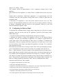
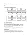
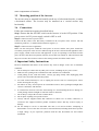
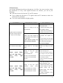
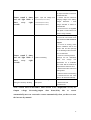
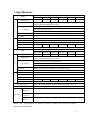
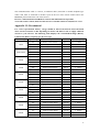
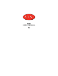
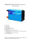
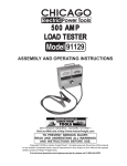
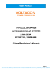
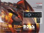
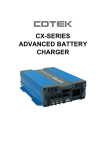
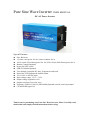
Pure Sine Wave Inverter USER MANUAL DC-AC Power Inverter Special Features: Fuse: Built-out 1.5 times rated power for 10s,2 times continue for 2s 120%<Load<150% Rated power for 10s,150%<Load<200% Rated power for 2s Remote Control(Optional) Power ON-OFF switch USB:5V,500mA(Optional) Two multiple controlled DC fans: Temperature and Load. Protection: LED Indicator& Audible Alarm. 12V or 24V or 48VDC input Input voltage range: -15% ~ +25% Output voltage regulation: 10% Output waveform: Pure sine wave Frequency: 50Hz±1%,60±1%,50Hz/60Hz(Optional) switch, switch by manual CE and RoHS Approved Thank you for purchasing ours Pure Sine Wave Inverter, Please Carefully read, understand and comply with all instructions before using. Table of contents 1. Introduction………………………………………………………….3 1.1 What’s an inverter…………………………………………….3 1.2 Pure Sine Wave Inverter……………………………………. .3 2. Main Components………………………………………………...3-6 2.1 Front panel…………………………………………………….5 2.2 Rear panel………………………………………………...…...6 3. How to Use Inverter….…………………………………….…..…...6 3.1 Load consideration………………………………………….…6 3.2 Configuring the Battery Bank …………………………...……7 3.3 Battery wiring examples………………………………….……8 3.4 Placement of the inverter…………………………….………..8 3.5 Mounting position of the inverter…………………….………9 3.6 Getting Connected……………………………………….…….9 4. Important Safety Instructions………………………………………9 5. Protection Feature………………………………………………….10 6. Troubleshooting Reference………………………………...…........10 7. Main Specifications………………………………………...............13 8. Maintenance………………………………………………………..14 9. Warranty……………………………………………………….…..14 Appendix I: Remote Control Switch ………..…………………….14 Appendix I I: Recommend………….……………………………..…15 Notice that specifications and product functionality may change without notice. 2 1. Introduction 1.1 What is an Inverter? Power inverter is an electronic device that convert DC(Direct Current) battery power to standard AC(Alternating Current) power. DC is the power that is produced by battery while AC is the standard power needed to run electrical equipment. A power inverter does the opposite of a rectifier and is used in places and situations where AC power is not available. 1.2 Pure Sine Wave Inverter If you want to run your equipment exactly to the manufacturer’s specifications, choose a pure sine wave inverter. With pure sine wave, motor loads start easier and run cooler. Some equipment only operate properly with pure sine wave inverter, such as laser printers, variable speed motors and digital clocks. 2. Main Components 2.1 Front Panel The front panel view shows the inverter’s ON/OFF Switch, AC Output Receptacle, LED Indicator Light, Vent Outlet, Remote Control port 3 A. ON/OFF Switch. This switch controls ON/OFF operation of the inverter. B. LED Indicator Light: Fault, Inverter. a) Fault: Turns Red shows fault, reference to Troubleshooting b)Inverter: This light will illuminate continuously whenever connected equipment is receiving battery-supplied, inverted AC power. C. AC Output Receptacle: For application demands of different geographic areas all over the world, there are many different kinds of optional AC receptacle to choose from. D. Vent Outlet. To decrease the temperature of the inverter. E. Chassis Ground Properly grounds the Inverter to vehicle grounding system or to earth ground. F. Remote Switch Port(Optional): Use to connect the remote ON/OFF switch via a communication cable. Refer to Appendix G. Hardwire Terminal Block(2500W to 6000W): Note: When the load current is >15A, must use output terminal connection which can be found inside the AC output panel of the inverter. Ensure the inverter is turned off if connecting the Hard Wire option. 4 "L" means LIVE WIRE, "G" means GROUND WIRE, "N" means Null Line Seek professional assistance if you are unfamiliar with electrical wiring. I. USB Port(Optional): Powers and charges USB-enabled devices. 2.2 Rear Panel The rear panel view shows the inverter’s Cooling fan, DC Battery Terminals, Fuse, Chassis Ground A. Temperature and Load controlled Multi-Speed Cooling Fan Quiet, efficient fan prolongs equipment service life. 1. Load<40% or inner temperature less than 30℃,fan don’t run 2. 40%<Load<60%,the fan’s rotational speed is 40% 3. 60%<Load<80%,the fan’s rotational speed is 60% 4. 80%<Load<100%,the fan’s rotational speed is 80% 5. 100%<Load, the fan’s rotational speed is 100% Once Inner temperature is more than 45℃, the fan’s rotational speed is 100%. B. DC Battery Terminals Connect the inverter to battery or other power sources. 5 Negative (-) and Positive (+) DC terminals should be kept insulated to protect from accidental short circuits. a) Connect the black cable to the black post marked (-) on the back of the inverter. Connect the other end to the negative terminal on the battery. b) Connect the red cable to the red post marked (+) on the back of the inverter. Connect the other end to the positive terminal on the battery. If you connect the cables to the incorrect terminals, you will reverse the polarity and damage the inverter. PROHIBITED REVERSE POLARITY. DAMAGE CAUSED BY REVERSE POLARITY WILL NOT BE COVERED BY WARRANTY. C. Fuse Fuse was built-out is a very good design as you can very easy to change the fuse outside the inverter if your inverter fuse was blown. 3. How To Use Inverter 3.1 Load consideration When an appliance with a motor starts, it requires a momentary surge of power. This surge of power is the “starting load” or “peak load”. Once started, the appliance requires less power to continue to operate. This is known as the “continuous load”. It is important to know the starting loads and the continuous loads of the appliances that are to be powered by the inverter. Appliance power is rated in watts. This information is usually stamped or printed on most appliances and equipment. In some cases, a tool will be rated in amperes. To convert from amps to watts, multiply: 6 Amps x AC voltage = Watts This formula yields an approximation of the continuous wattage load of that appliance. The startup load of an appliance is a major factor of whether this inverter can power it. Startup load is momentary. With many appliances, it is approximately twice the continuous load, but some appliance startup loads can be as high as eight times the continuous load. To determine if an appliance or tool will operate with this inverter, run a test. This inverter will automatically shut down in the event of an output overload, so there is no danger of damaging either the inverter or the equipment. When lit, a red LED indicator and Buzzer signals a fault. 3.2 Configuring the Battery Bank To determine the minimum battery ampere-hour rating that you will need to operate appliances from the inverter and any DC appliances powered by the battery bank, follow these steps: 1. List the maximum continuous wattage that the inverter has to supply. 2. Estimate the number of hours the appliances will be in use between battery recharges. This will vary depending on appliances. For example, a typical home-use coffee maker draws 500 watts during its brew time of 5 minutes. It maintains the temperature of the pot, requiring 100 watts. Typical use of a microwave oven is only for a few minutes. Some longer operating time appliances are lamps, TVs, computers and refrigerator/freezers. Determine the total watt-hours of energy needed. This is done by multiplying average power consumption in watts by hours of run time. For example: 500 watts for 10 hours = 5000 watt hours. To get an estimate of the maximum current (in amps) that a battery bank must be capable of delivering to the inverter, divide the load watts by ten. For example a 500 watt appliance load will need 50 amps at 12 volts DC. Using the 500 watts (or 50 amps) for 10 hours example as above, then 50 amps is needed for 10 hours. This provides us with the basic amp-hours (AH) of battery that is required. Ten hours at 50 amps equals 500 amp-hours (AH). There are additional factors that determine actual run time. These include: •AC appliance load and time in use (basic AH). • Cable gauge and length (cable losses). • Charge level of the batteries (between use, chargers have to be able to fully charge the batteries). • Temperature of the batteries (colder batteries provide fewer amps). • Age and condition of the batteries (older batteries lose AH capacity). • Compliance with turning off unnecessary AC loads. • Use of DC appliances and compliance with turning off unnecessary DC loads. 7 3.3 Battery Wiring Examples In renewable energy systems, batteries are connected to each other in one of three ways: • Series (voltage increases, amperage stays the same as a single battery) • Parallel (voltage stays the same as a single battery, amperage increases) • Series/Parallel (both voltage and amperage increase) 3.4 Placement of inverter The location where to install inverter must be: A. Dry: Do not allow water to drip or splash onto it. B. Cool: Ambient air temperature should be between 0º C and 40º C - ideally between 15º C and 25º.Do not place the inverter on or near a heating vent or any piece of equipment which is generating heat above room temperature. Do not place the inverter in direct sunlight unnecessarily. C. Ventilated: Allow at least one inch of clearance around the unit for air flow. Do not place items on or over the inverter during operation. Make sure that air is allowed to circulate freely around the unit. A fan is helpful in the case where the inverter is operating at maximum D. Safe: Do not install the inverter in the same compartment as the batteries or in any compartment where flammable liquids or fumes may be or may become present. E. Dust Do not install the inverter in a dusty environments. The dust can be inhaled into the unit when the cooling fan is working. F. Close to batteries: Avoid excessive cable lengths. Do not install the inverter in the 8 same compartment as batteries. 3.5 Mounting position of the inverter The inverter may be mounted horizontally on the top of a horizontal surface or under a horizontal surface. The inverter may be mounted on a vertical surface only horizontally. 3.6 Connections Follow the connection sequence described below. Step 1 Ensure that the ON/OFF switch on the Inverter is in the OFF position. If the power source is a DC power supply, switch it OFF as well. Step 2 Connect inverter to power source. Connect the DC cables to the DC battery terminals on the rear panel of the inverter. The red terminal is positive (+) and the black terminal is negative (-). Step 3 Connect inverter to appliances. Make sure the load power within the rated power of inverter and the start power should not exceed the peak power of the inverter. When having the inverter connected with appliances and a power supply, switch on the inverter and appliances. If you are operating several loads from the power inverter, turn them on separately after the inverter has been turned on. This will ensure that the power inverter does not have to deliver the starting currents for all the loads at once. 4. Important Safety Instructions Incorrect installation and misuse of the inverter may result in danger to the user or hazardous conditions. 1. Do not attempt to connect the any other power source, including any AC power source . 2. Make sure the opening to the ventilation fan and vent holes are not blocked. 3. Avoid pulling on the cords and cables. Always grip plugs firmly when unplugging from power source and when disconnecting cables. 4. To avoid electrical hazard, be sure to unplug the inverter from its external power source before inserting the AC plug. 5. For indoor use only. Avoid exposure to external heat sources; direct, prolonged sunlight; dust; corrosive chemicals; and moisture. 6. It is normal for inverters to become warm during use. Avoid touching the device during use. Avoid placing in direct sunlight or near heat-sensitive materials. 7. Do not drop or subject the inverter to undue shock. 8. Do not place anything on top of the inverter. 9. Always with the supplied cables and connectors as shown. Use of cables, connectors, or accessories not supplied with this product constitutes misuse and may result in injury or damage. 10. Do not attempt to service or dissemble. The unit is not user-serviceable. Attempting to disassemble or service the unit can result in electrical hazard, including death from exposure to high voltage. If you experience problems with the unit, discontinue use and Contact Technician. 9 11. When cleaning the inverter, please switch off power(unplug the inverter).Carefully clean with dry cloth. Do not use wet cloth or cleanser. 12. Disconnect all AC and DC side connections before working on any circuits associated with the inverter. Turning the ON/OFF switch on the inverter to off position may not entirely remove dangerous voltage. 13. Keep away from children. 5. Protection Feature Inverter is equipped with numerous protection features to ensure safe operation. Input Low Voltage Protection: A: When battery voltage is below 10.8V±0.2V(for 12V input inverter)/21.6V±0.4V(for 24V input inverter)/ 43.2V±0.8V(for 48V input inverter), Buzzer sound 2times and red light blink 2 times every eight seconds, which indicates DC power supply voltage is descending and batteries need to recharge. B: When input voltage is below 10.2V±0.2V(for 12V input inverter)/20.4V±0.4V(for 24V input inverter)/ 40.8V±0.8V(for 48V input inverter), Buzzer sound 3 times and red light blink 3times every eight seconds, AC output will be automatically shut off. Input Over Voltage Protection When input voltage reach 15.5V±0.2V (for 12V input inverter)/31V±0.4V (for 24V input inverter)/62V±0.8V (for 48V input inverter), Buzzer sound 4times and red light blink 4 times every eight seconds, the AC output will be shut off automatically. Short Circuit Protection When short circuits occur, red light constantly flashing, output will be shut off. Overload Protection When overloads occur, red light constantly flashing, output will be shut off. Reverse polarity protection:Fuses or Mosfet a. via Fuses:When battery terminals are reverse connected, fuse will be burned to protect appliances. b. Via Mosfet(optional): When battery terminals are reverse connected, the inverter won’t work unit correct connect. Over Temperature Protection When heat sink temperature exceeds 45ºC, the inner cooling fan will automatically turn on to cool the inverter; when less than 30ºC,the inner cooling fan will automatically shut off. When inner temperature exceeds 75ºC, AC output will automatically shut off, Buzzer sound 5 times and red light blink 5times every eight seconds, 6.Troubleshooting Reference Acoustics buzzer alarms When applying the inverter to acoustics devices, some inferior acoustics devices will buzz, this is because the output wave from the inverter is modified sine wave inverter. 10 TV Interference You can get minimum interference through use of a filter. On some occasions, when the interference of every weak signals becomes too obvious, you can try the following: Place the inverter far from the TV and TV antenna. Try to change the direction of TV signals cable and TV antenna to reduce the interference to minimum. Use screen cable antenna of highly quality. SYMPTOM POSSIBLE CAUSE SOLUTIONS 1. Check the continuity of the battery input circuit There is no voltage at the DC 2. Check that the battery fuse is input Terminals intact. Replace if blown 3. Check that all connections in ON/OFF switch is switched on, the battery input circuit are tight LED does not light. Buzzer is Correct the polarity of the input off. There is no AC voltage Polarity of the input voltage has connections and replace the been reversed that has blown the fuse. DC side fuses. If the unit does not work after ( Note: Reverse polarity may replacing the fuse, the unit has cause permanent damage) been permanently damaged Call Technical Support Buzzer alarm is sounded 1 1.Loose AC output connections. 1.Tighten AC output connections time. There is no AC voltage. 2.Short circuit of 2.Check AC wiring for short AC Output wiring. circuit. 1.Check that the battery is fully Buzzer sound 2times and red light blink 2 times every eight seconds Voltage at the DC input terminals reads below 10.8±0.2VDC(12V version),21.6±0.4VDC(24V version),43.2±0.8VDC(48V version). charged. Recharge, if low 2. Check that the battery cables are thick enough to carry the required current over the required length. Use thicker cables, if required 3. Tighten connections of the battery input circuit 1.Check that the battery is fully charged. Recharge, if low Buzzer sound 3times and red light blink 3 times every eight seconds Voltage at the DC input terminals reads below 10.2±0.2VDC(12V version) 20.4±0.4VDC(24V version) 40.8±0.8VDC(48V version) 2. Check that the battery cables are thick enough to carry the required current over the required length. Use thicker cables, if required 3. Tighten connections of the battery input circuit. 11 1. Check that the voltage at the DC input terminals is more than 15V/30V/60V DC. Buzzer sound 4 times and red light blink 4 times every eight seconds Higher input DC voltage than 2. Ensure that the maximum 15.5±0.2VDC(12V version), charging voltage of the battery 31±0.4VDC(24V version), charger 62±0.8VDC(48V version) charge controller is below 15 /alternator / solar V/30V/60VDC 3. Ensure that an un-regulated solar panel or wind turbine is not used to charge a battery 1. Check that the fan is working. If not, the fan / fan control circuit may be defective Call Technical Support 2. If the fan is working, check that the ventilation slots on the suction side and the openings on the discharge side of the fan are not obstructed Buzzer sound 5 times and red light blink 5 times every eight seconds 3. If the fan is working and the System overheating openings are not obstructed, check that enough cool replacement air is available. Also check that the ambient air temperature is less than 45º C 4. Reduce the load to reduce the heating effect 5. After the cause of overheating is removed and the unit cools down, it will reset automatically Red light constantly flashing The loads is 200% higher than 1. Disconnect the load rated power. 2. Reduce the load 3.Cool the unit. Note:* When 190%<Load<200%, limit current of AC output,that's to say AC Output voltage decreasing,output shut down,delay 60s to restart automatically,once ten consecutive restart automatically, then you have to start the inverter by manual. 12 7. Specifications Item Rated Power O U T P U T I N P U T Surge Power I N P U T SR-500-S 300W 500W 600W 1000W SR-1500-S SR-2000-S 1500W 2000W 120%<Load<150% Rated power for 10s 150%<Load<200% Rated power for 2s 100V/110V/115V/120Vac or 220V/230V/240Vac AC Voltage AC output regulation: 10% Frequency:50Hz±1%,60±1%,50/60Hz(Optional),switch by manual Waveform Pure Sine Wave Inverter(THD<3%) at rated input voltage Protection AC short circuit, Overload, Over temperature Bat. Voltage Range 10.8V-15.5V(12V version) 21.6V-31V(24V version) 43.2V-62V(48V version) Efficiency More than 85% Protection Battery Low Alarm, Battery Low Shutdown, Battery Polarity Reverse by Fuse Battery Types Open & sealed lead acid battery Item O U T P U T SR-300-S Model SR-600-S SR-1000-S Rated Power Surge Power SR-2500-S SR-3000-S 2500W 3000W Model SR-4000-S SR-5000-S 4000W 5000W SR-6000-S 6000W 120%<Load<150% Rated power for 10s 150%<Load<200% Rated power for 2s 100V/110V/115V/120Vac or 220V/230V/240Vac AC Voltage AC output regulation: 10% Frequency:50Hz±1%,60±1%,50/60Hz(Optional),switch by manual Waveform Pure Sine Wave Inverter(THD<3%) at rated input voltage Protection AC short circuit, Overload, Over temperature Bat. Voltage Range 10.8V-15.5V(12V version) 21.6V-31V(24V version) 43.2V-62V(48V version) Efficiency More than 85% Protection Battery Low Alarm, Battery Low Shutdown, Battery Polarity Reverse by Fuse Battery Types Open & sealed lead acid battery AC Out Receptacle USA, UK, Germany, France, Australia, Brazil, Italy, South Africa, etc. Cooling Operating Temperature and Load Controlled -15 ° C to 40° C Temperature Environment Storage -40 to 85°C Temperature Relative 20% ~ 90% RH non-condensing Humidity Note: *The specifications are subject to change without prior notice for further improvement of products. 13 8. Maintenance To keep your inverter operating properly, there is very little maintenance required. You should clean the exterior periodically with a dry cloth to prevent accumulation of dust and dirt. At the same time, tighten the screws on the DC input terminals. 9. Warranty We guarantee this product against defects in materials and workmanship for a period of 12 months from the date of retail purchase by end user. This warranty will be considered void if the unit has been misused, altered, or accidentally damaged. We are not liable for anything that occurs as a result of the user’s fault. If the warranty period for your product has expired, if the unit was damaged by misuse or incorrect installation, if other conditions of the warranty have not been met, or if no dated proof of purchase is available, your unit may be serviced or replaced for a flat fee. Appendix Appendix I: Remote Control Switch ● Power ON/OFF Switch Power ON/OFF switch is to turn the inverter on or off. ●Battery Capacity/Load Voltage indicator Load: Slow flash, 1time per 1seconds. Show the approximate connected equipment load level. Five Levels---20%,40%,60%,80%,100%. Battery: Solid green. Show the battery residual capacity. Five Levels---20%,40%,60%,80%,100%. Transfer time(Between Load and battery ):1time per 8seconds ● Standby/AC ON Indicator ● Standby: Slow flash, load power is less than 5% of rated power or standby; conversely,solid green. ● AC ON: solid green, inverter’s output is continuous ● Fault: Turns red show fault, refer to Troubleshooting of Invertr Manual. Connecting the Communications Cable 14 The communications cable is 3 meters, 6-conductor cable (wired like a normal telephone-type cable). This cable is connected to the RJ11 jack on the rear of the remote control and to the REMOTE port located on the rear of the inverter. Inverter’s ON/OFF Switch and Remote control’s ON/OFF Switch is in parallel. To use this remote control, must turn the inverter’s ON/OFF Switch to OFF,and vice versa. Appendix I I: Recommend For correct operation,the battery voltage should be between 0.9xVnom and 1.29xVnom where Vnom is 12V,24V or 48V depending on model, and must be able to supply sufficient current to your inverter. The following table displays the recommended things (Battery Cables,Fuses,Battery Capacity) per inverter type. Inverter Type 300W 500W/600W 1000W 1500W 2000W 2500W 3000W 4000W 5000W 6000W Input Voltage DC Battery Cable Fuse Battery Capacity 12V 4mm²(1*red/1*black) 35A*1 ≥ 50Ah 24V 2.5mm²(1*red/1*black) 20A*1 ≥ 25Ah 48V 2.5mm²(1*red/1*black) 10A*1 ≥ 12Ah 12V 6mm²(1*red/1*black) 35A*4 ≥ 100Ah 24V 4mm²(1*red/1*black) 20A*4 ≥ 50Ah 48V 2.5mm²(1*red/1*black) 10A*4 ≥ 25Ah 12V 10mm²(1*red/1*black) 35A*4 ≥ 160Ah 24V 6mm²(1*red/1*black) 20A*4 ≥ 80Ah 48V 4mm²(1*red/1*black) 10A*4 ≥ 40Ah 12V 10mm²(2*red/2*black) 35A*6 ≥ 250Ah 24V 6mm²(2*red/2*black) 20A*6 ≥ 125Ah 48V 4mm²(2*red/2*black) 10A*6 ≥ 60Ah 12V 16mm²(2*red/2*black) 35A*8 ≥ 320Ah 24V 10mm²(2*red/2*black) 20A*8 ≥ 160Ah 48V 6mm²(2*red/2*black) 10A*8 ≥ 80Ah 12V 16mm²(2*red/2*black) 35A*10 ≥ 400Ah 24V 10mm²(2*red/2*black) 20A*10 ≥ 200Ah 48V 6mm²(2*red/2*black) 10A*10 ≥ 100Ah 12V 16mm²(2*red/2*black) 35A*12 ≥ 480Ah 24V 10mm²(2*red/2*black) 20A*12 ≥ 240Ah 48V 6mm²(2*red/2*black) 10A*12 ≥ 120Ah 12V 25mm²(2*red/2*black) 35A*12 ≥ 640Ah 24V 16mm²(2*red/2*black) 20A*12 ≥ 320Ah 48V 10mm²(2*red/2*black) 10A*12 ≥ 160Ah 12V 35mm²(2*red/2*black) 35A*20 ≥ 800Ah 24V 25mm²(2*red/2*black) 20A*20 ≥ 400Ah 48V 16mm²(2*red/2*black) 10A*20 ≥ 200Ah 12V 35mm²(2*red/2*black) 35A*20 ≥ 960Ah 24V 25mm²(2*red/2*black) 20A*20 ≥ 480Ah 48V 16mm²(2*red/2*black) 10A*20 ≥ 240Ah 15