1
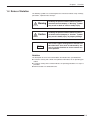
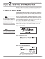
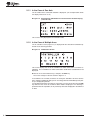
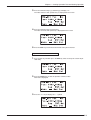
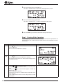
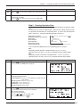
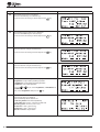
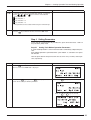
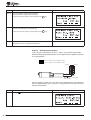
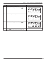
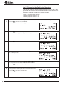
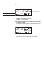
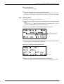
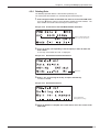
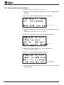
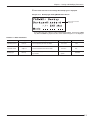
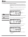
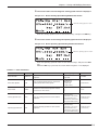
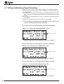
HL-0134-2
EZS/EZC Series Controller
DATA SETTING MANUAL
ORIENTAL MOTOR CO., LTD.
Notes to the User
● This product must be handled by qualified personnel with expert knowledge of elec-
trical and mechanical engineering.
● Should you require the inspection or repair of internal parts, please contact the
Oriental Motor branch or sales office from which you purchased the product.
● The figures and tables provided in this document are intended to help you under-
stand the content of the text. They should not be construed in any way as guaranteeing the resultant operation.
● Oriental Motor shall not be liable whatsoever for any patent-related problem arising in connection with the use of any information, circuit, equipment or device described in this document.
● The technical specifications are subject to change without prior notice for the purpose of improvement in product performance.
● This document is protected under the applicable copyright laws. No part of this
document may be reproduced, stored, changed, duplicated or transmitted digitally
(via printing, copying, microfilming or any other manner) without prior written consent from Oriental Motor.
●
and
are trademarks of Oriental Motor Co., Ltd.
● Other product names and company names are the trademarks or registered trademarks of their respective companies. The products by other manufacturers referred
to in this installation manual are mentioned for reference purposes only; their use
is not enforced in any way. Oriental Motor shall not be liable whatsoever for the
performance of another manufacturer’s product or any problem arising from the use
thereof.
© Copyright ORIENTAL MOTOR CO., LTD. 2002
4
Table of Contents
Chapter
1 Overview
1.1
1.2
1.3
1.4
Chapter
…………………………………………… 1- 1
Introduction …………………………………………… 1- 1
Functions of the Teaching Pendant ………………… 1- 1
Contents of the Manual ……………………………… 1- 2
Rules of Notation ……………………………………… 1- 3
2 Startup and Operation
……………… 2- 1
2.1 Starting the Teaching Pendant ……………………… 2- 1
2.1.1 In the Case of One Axis ……………………… 2- 2
2.1.2 In the Case of Multiple Axes ………………… 2- 2
2.1.3 Switching Between Languages ……………… 2- 3
2.1.4 First Screen of Each Mode …………………… 2- 3
2.1.5 Error Display Screens ………………………… 2- 6
Chapter
3 Creating Operation Data
and Starting Operation
…………… 3-1
3.1 Procedure for Creating Slider Operation Data
and Starting Operation………………………………… 3-2
3.2 Procedure for Creating Cylinder Operation Data
and Starting Operation………………………………… 3-11
Chapter
4 Creating and
Modifying Operation Data ……… 4 -1
Operation Data ………………………………………… 4 -1
Functions Available in the PRG Mode ……………… 4 -2
Operation Data Creation Screens …………………… 4 -2
Creating New Operation Data ……………………… 4 -3
Editing Operation Data ……………………………… 4 -6
4.5.1 Editing Existing Data ………………………… 4 -6
4.5.2 Clearing Data…………………………………… 4 -7
4.5.3 Inserting Data ………………………………… 4 -8
4.5.4 Deleting Data …………………………………… 4 -9
4.6 Clearing All Operation Data ………………………… 4 -10
4.7 Remote Teaching ……………………………………… 4 -11
4.8 Direct Teaching ………………………………………… 4 -13
4.9 Setting Range of Operation Data …………………… 4 -15
4.10 Performing Positioning Operation …………………… 4 -16
4.1
4.2
4.3
4.4
4.5
EZS/ EZC Series Controller DATA SETTING MANUAL
i
Chapter
5 Setting and
Modifying Parameters ……………… 5 -1
5.1
5.2
5.3
5.4
5.5
5.6
5.7
5.8
5.9
Chapter
Parameters……………………………………………… 5 -1
Functions Available in the PAR Mode ……………… 5 -1
Parameter Setting Screens…………………………… 5 -2
Setting and Modifying I/O Parameters ……………… 5 -3
Setting and Modifying Motor Parameters…………… 5 -6
Setting and Modifying Home Parameters ………… 5 -8
Setting and Modifying Speed Parameters ………… 5 -10
Setting and Modifying Common Parameters ……… 5 -12
Initializing All Data …………………………………… 5 -15
6 Monitoring Operation Data
…… 6 -1
6.1 Monitoring Functions ………………………………… 6 -1
6.2 Monitor Items Available in the EXT Mode ………… 6 -2
6.3 Descriptions of Monitor Screens …………………… 6 -4
Chapter
7 Manual Operation and
I / O Checking
………………………………… 7-1
7.1 Manual Operation ……………………………………… 7-1
7.1.1 Manual Operation ……………………………… 7-1
7.1.2 Positioning Operation ………………………… 7-2
7.2 I/O Checking …………………………………………… 7-3
7.2.1 I/O Checking Items …………………………… 7-4
Chapter
8 Troubleshooting
…………………………… 8-1
8.1 Error Messages ………………………………………… 8-1
8.2 Checking the Alarm History ………………………… 8-3
ii
Appendix
A Table of Operation Switching
…A-1
A.1 External (EXT) Mode Operation Monitor
< Controller Mode > (English display) …………………A-1
A.2 Program (PRG) Mode Operation Data Setting
< Controller Mode > (English display) …………………A-2
A.3.1 Parameter (PAR) Mode 1 Parameter Setting
< Controller Mode > (English display) ………………A-3
A.3.2 Parameter (PAR) Mode 2 Parameter Setting
< Controller Mode > (English display) ………………A-4
A.4 Test (TST) Mode Manual Drive and I/O Checking
< Controller mode > (English display) …………………A-5
A.5 External (EXT) Mode Operation Monitor
< Driver Mode > (English display) ………………………A-6
A.6 Parameter (PAR) Mode 1 Parameter Setting
< Driver Mode > (English display) ………………………A-7
A.7 Test (TST) Mode I/O Checking
< Driver Mode > (English display) ………………………A-8
A.8 External (EXT) Mode Operation Monitor
< Controller Mode > (Japanese display) ………………A-9
A.9 Program (PRG) Mode Operation Data Setting
< Controller Mode > (Japanese display) ………………A-10
A.10.1 Parameter (PAR) Mode 1 Parameter Setting
< Controller Mode > (Japanese display) ……………A-11
A.10.2 Parameter (PAR) Mode 2 Parameter Setting
< Controller Mode > (Japanese display) ……………A-12
A.11 Test (TST) Mode Manual Drive and I/O Checking
< Controller mode > (Japanese display) ……………A-13
A.12 External (EXT) Mode Operation Monitor
< Driver Mode > (Japanese display) …………………A-14
A.13 Parameter (PAR) Mode 1 Parameter Setting
< Driver Mode > (Japanese display) …………………A-15
A.14 Test (TST) Mode I/O Checking
< Driver Mode > (Japanese display) …………………A-16
EZS/ EZC Series Controller DATA SETTING MANUAL
iii
iv
Chapter
1 Overview
1.1 Introduction
Chapter 1 Overview
This manual describes how to set data for the EZS/EZC Series controller using the
EZT1 teaching pendant.
Operating any EZS/EZC Series slider or cylinder requires the setup of the slider/cylinder and controller, as well as the creation of operation data via a teaching pendant.
Please refer to the following manuals for the EZS/EZC Series, and follow the instructions:
● EZS/EZC Series Controller Data Setting Manual (this document)
● EZS/EZC Series Slider/Cylinder Installation Manual
This manual explains the installation and troubleshooting of the slider and cylinder.
● EZS/EZC Series Controller User Manual
This manual explains the installation, wiring, I / O, setting and troubleshooting of the
controller.
● Teaching Pendant EZT1 User Manual
This manual explains the key layout of the teaching pendant.
1.2 Functions of the Teaching Pendant
It is possible to create and monitor operation data for up to 16 controllers with one
teaching pendant.
● A unique individual axis number (ID) must be set for each controller.
● Controller link cables (optional) are required for the connection of the controllers.
The following modes can be executed with the teaching pendant if a controller is set
to the controller mode:
● External
(EXT) mode:
Perform operation via the controller’s I / O and monitor
command position, I / O status, alarms and alarm
history.
● Program (PRG) mode:
Create and modify operation data, as well as clear all
data.
● Parameter (PAR) mode: Set and modify parameters for operation and function
settings.
● Test (TST) mode:
Perform manual operation and I / O checking.
The following modes can be executed with the teaching pendant if a controller is set
to the driver mode:
● External
(EXT) mode: Perform I / O status, alarms and alarm history.
(PAR) mode: Set and modify parameters for operation and function
settings.
● Test (TST) mode:
Perform I / O checking.
● Parameter
Operation data can be created using any one of the following three options:
● Numerical
value input: Enter numerical values using the numerical keys.
teaching input: Operate the slider/cylinder with the arrow keys to enter
the stopping position.
● Direct teaching input:
Move the slider/cylinder manually to enter the stopping
position.
● Remote
EZS/ EZC Series Controller DATA SETTING MANUAL
1-1
1.3 Contents of the Manual
This manual consists of chapters 1 through 8 and appendixes A. The table below
gives a brief explanation of the content of each chapter and section.
Chapter
1-2
Description
Chapter 1
Overview
This chapter gives an overview of the functions of the teaching pendant and the contents
of this manual.
Chapter 2
Startup and Operation
This chapter explains how to perform a self-check at startup and select each menu.
Chapter 3
Creating Operation Data
and Starting Operation
This chapter provides examples of how to create operation data for sliders/cylinders,
as well as examples of operation control.
Chapter 4
Creating and
Modifying Operation Data
This chapter explains how to create and modify data for positioning operation.
Chapter 5
Setting and
Modifying Parameters
This chapter explains how to set and modify common parameters for operation and
parameters for setting controller functions.
Chapter 6
Monitoring Operation Data
This chapter explains the minimum maintenance required for the controller.
Chapter 7
Manual Operation
and I/O Checking
This chapter explains how to perform manual operation and operation check of controller
I/O via the teaching pendant.
Chapter 8
Troubleshooting
This chapter explains how to check error messages and alarm history, as well as the
appropriate actions to be taken.
Appendix A
Table of
Operation Switching
This section describes the operations of the teaching pendant and how the screens shift.
Chapter 1 Overview
1.4 Rules of Notation
The following symbols are used throughout this manual to indicate safety warnings,
precautions, important notes and tips:
Warning
Handling the product without observing the instructions that accompany a “Warning” symbol
may result in death or serious bodily injury.
Caution
Handling the product without observing the instructions that accompany a “Caution” symbol
may result in bodily injury or property damage.
Note
These notes appear throughout the manual and
describe items that must be observed by the
user in certain situations to ensure correct use
of the product.
Notation
The description of text in this manual follows the notation rules specified below:
● A sentence starting with a filled circle provides information, not an operating pro-
cedure.
● A sentence starting with a number indicates an operating procedure or a step in a
procedure.
● Referenced titles are denoted in italics.
EZS/ EZC Series Controller DATA SETTING MANUAL
1-3
1-4
2 Startup and Operation
Chapter 2 Startup and Operation
Chapter
This chapter describes the representative screens of the teaching pendant displayed
in the controller mode, as well as the basic key operations using those screens.
2.1 Starting the Teaching Pendant
The power to the teaching pendant is supplied from the controller via the cable connecting the teaching pendant and controller. This means the power is supplied to the
teaching pendant at the time the power supply to the controller is turned on if the teaching pendant is already connected to the controller and the pendant switch (PENDANT / PC) is turned to “ON ”.
Note
When the controller is of the absolute
type, an alarm will be generated if power is supplied under the following conditions. Take an appropriate action by
referring to “Alarm Codes ” on p. 8-4.
● The battery is not connected
● The battery is not charged
● The battery is used for the first time
The startup screen shown in Figure 2-1 is displayed for approximately a second after turning on the power supply to the teaching pendant, followed by the screen (Figure
2-2) indicating that the axis number (ID) of the connected controller is being checked.
The language setting screen (1) (Figure 2-3) is displayed after the ID checking screen
has been displayed only when the power supply is turned on for the first time. Press
the ← or → key to select a language, and press the ENT key.
When normal communication with the controller is established and there are no errors in ID settings, the default screen (Figure 2-4) will be displayed if one axis is used.
The ID selection screen (Figure 2-5) will be displayed if multiple axes are used.
■ Figure 2-1 Startup Screen
Note
Do not input the alarm clear signal via
user I / O while starting up the pendant.
This will cause a communication error.
■ Figure 2-2 ID Checking Screen
■ Figure 2-3 Language Setting Screen (1)
Either Japanese or English can be selected.
EZS/ EZC Series Controller DATA SETTING MANUAL
2-1
2.1.1 In the Case of One Axis
The ID number of the connected controller is displayed. (The example below shows
the display when the ID is 00.)
■ Figure 2-4 Default Screen (EXT Mode: First Screen / Current Position Display)
(when ID is 00)
This screen is only displayed in the controller mode.
2.1.2 In the Case of Multiple Axes
The ID selection screen ( Figure 2-5) is displayed for the selection of controllers operated via the teaching pendant.
■ Figure 2-5 ID Selection Screen
This screen displays the IDs of the controllers for which connections have been established. IDs of controllers for which connections could not be established are not
displayed.
● Enter an ID via the numerical keys, and press the ENT key.
The screen changes to the one shown in Figure 2-4.
In the SELECT ID: nn field, the lowest ID among the controllers for which connections could be established during the ID checking performed immediately after power-up is displayed by default.
It is possible to perform ID checking as many times as necessary by pressing the ESC
key while the first screen of the EXT or driver mode is displayed. If ID checking is
performed with this operation, the ID previously selected is displayed in the SELECT
ID field.
2-2
Chapter 2 Startup and Operation
2.1.3 Switching Between Languages
To switch display languages, call up the first screen (Figure 2 -4) of the EXT mode
and press the SHIFT key continuously.
After confirming that the screen changes to the one shown in Figure 2 -6, press the
F4 key to display the language setting screen (2) (Figure 2 -7). Press the ← or →
key to select a language, and press the ENT key.
■ Figure 2-6 Default Screen (when switching language)
■ Figure 2-7 Language Setting Screen (2)
Either Japanese or English can be selected.
2.1.4 First Screen of Each Mode
When power is supplied to the teaching pendant and the ID checking of controllers
has been completed, the default EXT mode main screen is displayed. Four modes —
PRG, PAR, TST and EXT— are provided at the same hierarchy. Press the F1 key in
order to switch among these modes.
■ Figure 2-8 Operation Modes
Startup screen
EXT mode
PRG mode
PAR mode
TST mode
EZS/ EZC Series Controller DATA SETTING MANUAL
2-3
(1) EXT Mode
Figure 2-9 shows the first screen of the EXT mode. The EXT mode is used to perform controller operations. It also allows the user to monitor I / O status and slider /
cylinder operation, as well as to display alarm information.
■ Figure 2-9 First Screen of the EXT Mode / Current Position Display
Command position
Selected operation data number
Controller ID
Press the [F4] key to switch to the
operation data information screen.
Press the [SHIFT] key and [F4] key
at the same time to switch to the
language setting screen.
Press the [F3] key to switch to the
alarm information screen.
Press the [F2] key to switch
to the I/O monitor screen.
Press the [F1] key to switch to the PRG mode.
(2) PRG Mode
Figure 2 -10 shows the first screen of the PRG mode. The PRG mode is used for the
creation and editing of slider/cylinder operation data.
■ Figure 2-10 First Screen of the PRG Mode / Number Selection 1
Selected operation data number
Controller ID
Data description
Press the [ENT] key to
enter/change the data.
Press the [F4] key to switch to a screen in
which you can confirm data deletion.
Press the [F3] key to switch to a screen in
which you can confirm data insertion.
Press the [F2] key to switch to a screen in
which you can confirm the clearing of data.
Press the [F1] key to switch to the PAR mode.
2-4
Chapter 2 Startup and Operation
(3) PAR Mode
Figure 2 -11 shows the first screen of the PAR mode. The PAR mode is used for the
creating / editing of common operation parameters and parameters for controller function settings.
■ Figure 2-11 First Screen of the PAR Mode / Item Selection 1
Press the [SHIFT] key to switch to another parameter setting screen.
Data description
Controller ID
Press the [F4] key to switch
to a screen for the setting of
return-to-home operation.
Press the [F3] key to switch to the
operating-current setting screen.
Press the [F2] key to switch
to the I/O setting screen.
Press the [F1] key to switch to the TST mode.
(4) TST Mode
Figure 2 -12 shows the first screen of the TST mode. The TST mode is used to perform manual operation of the slider / cylinder and check the I / O status.
■ Figure 2-12 First Screen of the TST Mode / Item Selection
Controller ID
Press the [F4] key to switch
to a screen in which you can
perform positioning operation.
Press the [F3] key to switch to a
screen in which you can perform
manual operation.
Press the [F2] key to switch
to the I/O checking screen.
Press the [F1] key to switch to the PRG mode.
EZS/ EZC Series Controller DATA SETTING MANUAL
2-5
2.1.5 Error Display Screens
The error screens shown in figures 2 -13 to 2 -16 are displayed if controller errors are
detected. The red backlight turns on if an error screen is displayed.
■ Figure 2-13 No ID Connected
Check the connection between the teaching pendant and controllers, as well as the
ID settings of the controllers, then press the F1 key to return to the ID checking screen.
■ Figure 2-14 ID Duplication
Check the ID settings of the controllers, and press the F1 key to return to the ID checking screen.
Press the F2 key to disconnect a controller with a duplicate ID.
■ Figure 2-15 Communication Error
Check the ID settings of the controllers, and press the F1 key to return to the ID checking screen.
Press the F2 key to disconnect a controller that generates communication errors.
■ Figure 2-16 No ID Recognized
Change the duplicated ID or remove the cause of communication error, and press the
F1 key to return to the ID checking screen.
2-6
Operation Data
3 Creating
and Starting Operation
Chapter 3 Creating Operation Data and Starting Operation
Chapter
This chapter describes the procedures used to create operation data and start the operation of the slider/cylinder via the teaching pendant. Operation data is created in
the same way for both sliders and cylinders. However, it is necessary that you understand the principles of “ push-motion operation ” in order to create operation data
for cylinders.
● In order to avoid injury and equipment damage, be
sure that engineers having expert knowledge of the
structure and operation of the EZS/EZC Series controllers and sliders/cylinders, along with an awareness
of the degree of risk involved in the operation, perform
the connection of the teaching pendant.
● In order to avoid injury and equipment damage, per-
Warning
form the following operation as the first operation after recovery of the power supply if the product is of the
absolute type.
● Perform return-to-home operation or absolute positioning operation.
● If an incremental positioning operation is performed
immediately after recovery of the power supply, the
following accidents may occur:
● If the moving part of the slider/cylinder has shifted during the battery backup period due to an external force, the new position of the moving part will
be recognized as the home in the positioning operation and the stopping position will deviate accordingly.
In this chapter the following operations are described in the sequence.
Note that the explanation here assumes that the installation and wiring of the slider,
controller and power supply are complete.
It is also assumed that the controller has been started in the controller mode, and that
two or more controllers are not connected via a daisy chain using controller link cables.
Please refer to Chapter 2, “ Startup and Operation ”, to fully understand the functions
of the display screens on the teaching pendant.
● Turning on the power supply
● Checking slider operations
● Creating operation data
● Setting parameters
● Performing the positioning operation
For the purpose of the explanations provided in this chapter, the minimum numerical
values and conditions are set for operation data and parameters. Default values are
used for the data displayed in screen images.
For convenience, data values shown in this manual include both metric and (imperial) units.
However, the EZT1 Teaching Pendant only displays metric units.
Operation data and parameters are saved even after the power supply to the controller is turned off. Refer to the procedure explained below for the editing of operation data and parameters.
EZS/ EZC Series Controller DATA SETTING MANUAL
3-1
3.1 Procedure for Creating Slider Operation Data and Starting Operation
This section explains the steps involved in checking slider operation, creating data
for positioning operation and performing positioning.
The setting values for position data must be adjusted according to the slider’s stroke.
Turn the controller’s switch (No. 4) to the “OFF ” position (controller mode).
Step 1 Turning on the Power Supply to the Controller
Turn on the power supply to the controller and confirm that communication between
the teaching pendant and controller is performed correctly.
When the communication is being performed correctly, the teaching pendant is automatically placed in the external (EXT) mode, and it displays the current position.
Step
Operation and explanation
1.1
Turn on the controller’s power supply.
The POWER LED of the controller lights in green. The startup screen
is displayed and communication with the controller starts (ID check).
When the ID check is complete, the RDY/ ALM LED lights in green and
the first screen of the EXT mode is displayed.
In the EXT mode it is possible to perform operation via the controller
I / O and monitor the operations.
Screen display
How to Enter Numerical Values in the Teaching Pendant
The basic operation for entry of numerical values is explained here, as it will be used
to create operation data in step 3.
The operation mode used in this case is the program (PRG) mode.
When you enter a numerical value using the numerical keys, the numerical value entered shifts from the right edge toward the left in order each time a numerical key is
pressed.
If you want to enter 15.000 for Pos (Position)
1. Press the F1 key and then press the ENT key twice to call up the screen for position entry.
2. Press the SHIFT key to clear the previous numerical value.
0000.000 is displayed.
3-2
Chapter 3 Creating Operation Data and Starting Operation
3. Press the numerical keys [ 1 ] and then [ 5 ] to display “ 15 ”.
The value 0000.015 mm (0.0006 inch) is displayed on the screen.
4. Press the numerical key [ 0 ] three times.
The value 0015.000 mm (0.59 inch) is displayed on the screen.
5. Press the ENT key to commit the numerical value you’ve entered.
If you want to enter -30.000 for Pos
1. Press the F1 key and then press the ENT key twice to call up the screen for position entry.
2. Press the SHIFT key to clear the previous numerical value.
0000.000 is displayed.
3. Press the + / - key to display the “- ” symbol.
EZS/ EZC Series Controller DATA SETTING MANUAL
3-3
4. Press the numerical key [ 3 ] to display “3”.
The value -0000.003 mm (-0.0001 inch) is displayed on the screen.
5. Press the numerical key [ 0 ] four times.
The value -0030.000 mm (-1.18 inch) is displayed on the screen.
6. Press the ENT key to commit the numerical value you’ve entered.
Step 2 Checking Slider Operations
In this step you perform manual operation and the return-to-home operation of the
slider in the test (TST) mode in order to confirm that there are no problems with slider operations.
Step
Operation and explanation
2.1
Press the F1 key three times in the first screen of the EXT mode to
select the TST mode.
The first screen of the TST mode is displayed.
3-4
2.2
Press the F3 key to select manual operation.
The screen for performing manual operation is displayed.
The absolute position relative to the home position is displayed in the
Pos field on the screen.
2.3
Press the
or
key to operate the slider.
If you press the
key, the slider will move to the motor side (default
value).
If you press the
key, the slider will move opposite the motor side
(default value).
Check the direction of movement.
Proceed to the next step if it is confirmed that the slider moves in the
correct directions.
If you cannot operate the slider, check the wiring between the slider
and controller.
Screen display
Chapter 3 Creating Operation Data and Starting Operation
Step
Operation and explanation
2.4
Press the
tion.
2.5
If the slider has returned to the home position normally, the slider operation check is complete.
Press the ESC key to switch to the first screen of the TST mode.
F4
Screen display
key for the slider to perform the return-to-home opera-
Step 3 Creating Operation Data
In this step you create operation data for positioning operation in the program (PRG)
mode.
It is necessary to create the following data. Note that the starting speed has been
set separately and cannot be set via operation data. (It can be set in the parameter
mode. Refer to 5.7, “Setting and Modifying Speed Parameters ”).
● Positioning method
● Position (distance of movement)
● Direction
● Acceleration
● Deceleration
● Operating speed
● Operation function
Motor side
Opposite the motor side
Operating speed
Acceleration
Deceleration
Position (travel amount)
In this example the following two sets of positioning data are created:
No.1:
Positioning method: Absolute, Position/direction: 45 mm (1.77 inch),
Operating speed: 300 mm/s (11.81 in/sec), Operation function: Single-motion
No.2:
Positioning method: Incremental, Position/direction: -24 mm (-0.94 inch),
Operating speed: 150 mm/s (5.91 in/sec), Operation function: Single-motion
Step
3.1
Operation and explanation
Press the
F1
Screen display
key twice to select the PRG mode.
The first screen of the PRG mode is displayed.
3.2
Enter the following data in data No. 01.
Positioning method: Absolute
Position/direction: 45 mm (1.77 inch) opposite the motor side from
home position
Operating speed: 300 mm/s (11.81 in/sec)
Acceleration: 1.5 m/s2 (4.92 ft / sec2)
Deceleration: 1.8 m/s2 (5.90 ft / sec2)
Operation function: Single-motion
3.3
Press the ENT key to allow editing the operation data.
The positioning-method setting screen is displayed.
Abs: Absolute positioning
Inc: Incremental positioning
Press the
or
key to select Abs or Inc.
Here, select Abs and press the ENT key.
EZS/ EZC Series Controller DATA SETTING MANUAL
3-5
Step
3.4
Operation and explanation
The position setting screen is displayed.
Enter the value 45 using the numerical keys.
Check to see that the setting is correct and press the
3.5
ENT
key.
ENT
key.
ENT
key.
The deceleration setting screen is displayed.
Enter the value 1.8 using the numerical keys.
Check to see that the setting is correct and press the
3.8
key.
The acceleration setting screen is displayed.
Enter the value 1.5 using the numerical keys.
Check to see that the setting is correct and press the
3.7
ENT
The operating-speed setting screen is displayed.
Enter the value 300 using the numerical keys.
Check to see that the setting is correct and press the
3.6
Screen display
The operation-function setting screen is displayed.
SingleMotion: Single-motion positioning operation
LinkedMotion: Linked-motion positioning operation
PushMotion: Push-motion operation
Press the
or
key to select SingleMotion, LinkedMotion or
PushMotion.
Here, select SingleMotion and press the ENT key.
3.9
The data number is automatically incremented by one, and the setting screen for No. 02 is displayed.
Enter the following data for data No. 02.
Positioning method: Incremental positioning
Position/direction: 24 mm (0.94 inch) to motor side
Operating speed: 150 mm/s (5.91 in/sec)
Acceleration: 1.8 m/s2 (5.90 ft / sec2)
Deceleration: 1.8 m/s2 (5.90 ft / sec2)
Operation function: Single-motion
3-6
Chapter 3 Creating Operation Data and Starting Operation
Step
3.10
Operation and explanation
Screen display
Press the ENT key.
The positioning-method setting screen is displayed.
Abs: Absolute positioning
Inc: Incremental positioning
Press the
or
key to select Abs or Inc.
Here, select Inc and press the ENT key.
3.11
The position setting screen is displayed.
Enter the value - 24 using the numerical keys.
Set the direction of movement using the +/- key.
Press the +/- key to display the “ - ” symbol.
The default values are as follows:
No display: Opposite the motor side
-: Motor side
Check to see that the setting is correct and press the
3.12
key.
ENT
key.
ENT
key.
The deceleration setting screen is displayed.
Enter the value 1.8 using the numerical keys.
Check to see that the setting is correct and press the
3.15
ENT
The acceleration setting screen is displayed.
Enter the value 1.8 using the numerical keys.
Check to see that the setting is correct and press the
3.14
key.
The operating-speed setting screen is displayed.
Enter the value 150 using the numerical keys.
Check to see that the setting is correct and press the
3.13
ENT
The operation-function setting screen is displayed.
SingleMotion: Single-motion positioning operation
LinkedMotion: Linked-motion positioning operation
PushMotion: Push-motion operation
Press the
or
key to select SingleMotion, LinkedMotion or
PushMotion.
Here, select SingleMotion and press the ENT key.
EZS/ EZC Series Controller DATA SETTING MANUAL
3-7
Step
3.16
Operation and explanation
Screen display
It is possible to enter up to 63 operation data from No. 01 to No. 63.
Use the
,
,
and
keys to select a certain data No.
key: Data No. + 1
key: Data No. - 1
key: Data No. + 10
key: Data No. - 10
It is also possible to select a data number using the numerical keys.
3.17
The operation data is now created.
Press the ESC key to switch to the first screen of the EXT mode.
Step 4 Setting Parameters
In this step you set parameters for areas 1 and 2 in the parameter (PAR) mode.
It is possible to set up to 20 parameter items via the teaching pendant. Here, areas
for area output are set. With area settings the controller activates the area output
when the slider’s table moves to a certain position.
If area 1 > area 2, the area output is active.
If area 1 < area 2, the area output is active.
Mechanical
home position
Area 2
Area 1
Travel limit
Here the setting is made in such a way that the area output becomes active when the
table is positioned between area 1 [45 mm (1.77 inch)] and area 2 [ 24 mm (0.94 inch) ]
from the home position.
Step
4.1
Operation and explanation
Press the
F1
key twice to select the PAR mode.
The first screen of the PAR mode is displayed.
3-8
Screen display
Chapter 3 Creating Operation Data and Starting Operation
Step
4.2
Operation and explanation
Hold down the SHIFT key and press the F4 key to display the first
screen for the setting of common parameters.
When the
SHIFT
key is pressed:
The push-distance setting screen is displayed.
When the
SHIFT
and
4.3
Press the
4.4
Enter the value 45 using the numerical keys.
F4
keys are pressed:
key five times to display the area 1 setting screen.
Check to see that the setting is correct and press the
4.5
The area 2 setting screen is displayed.
4.6
Enter the value 24 using the numerical keys.
Check to see that the setting is correct and press the
4.7
Screen display
ENT
key.
ENT
key.
The area parameters are now set.
Press the ESC key to switch to the first screen of the PAR mode.
EZS/ EZC Series Controller DATA SETTING MANUAL
3-9
Step 5 Performing the Positioning Operation
In this step you perform the slider positioning operation in the test (TST) mode.
The operation data created in step 3 is called up and used to actually operate the slider.
Positioning is performed according to the following procedure:
● Return to mechanical home operation
● Positioning operation of data No. 01
● Positioning operation of data No. 02
Step
5.1
Operation and explanation
Press the
F1
Screen display
key once to select the TST mode.
The first screen of the TST mode is displayed.
5.2
Press the
F4
key to select positioning operation.
The screen for performing positioning operation is displayed.
5.3
Press the
5.4
Check that data No. 01 is displayed, and press the
the positioning operation.
5.5
Select data No. 02 using the
,
,
and
keys.
It is also possible to select a data number using the numerical keys.
Press the
5.6
START
key to perform the return-to-mechanical home operation.
START
key to perform
key to perform the positioning operation.
Upon completion of the operations you’ve performed so far, the positioning-operation check is complete.
Press the
3-10
F4
F1
key to switch to the EXT mode.
Chapter 3 Creating Operation Data and Starting Operation
3.2 Procedure for Creating Cylinder Operation Data and Starting Operation
This section explains the steps involved in checking cylinder operation, creating data for positioning operation and performing positioning.
The setting values for position data must be adjusted according to the cylinder’s
stroke.
Step 1 Turning on the Power Supply to the Controller
Turn on the power supply to the controller and confirm that communication between
the teaching pendant and controller is performed correctly.
When communication is being performed correctly, the teaching pendant is automatically placed in the external (EXT) mode, and it displays the current position.
Step
Operation and explanation
1.1
Turn on the controller’s power supply.
The POWER LED of the controller lights in green. The startup screen
is displayed and communication with the controller starts (ID check).
When the ID check is complete, the RDY/ALM LED lights in green and
the first screen of the EXT mode is displayed.
In the EXT mode it is possible to perform operation via the controller
I / O and monitor operations.
Screen display
Step 2 Checking Cylinder Operations
In this step you perform manual operation and the return-to-home operation of the
cylinder in the test (TST) mode in order to confirm that there are no problems with
cylinder operations.
Step
2.1
Operation and explanation
Press the
F1
Screen display
key three times to select the TST mode.
The first screen of the TST mode is displayed.
2.2
Press the F3 key to select manual operation.
The screen for performing manual operation is displayed.
The absolute position relative to the home position is displayed in the
Pos field on the screen.
2.3
Press the
or
key to operate the cylinder.
If you press the
key, the cylinder will move to the motor side (default value).
If you press the
key, the cylinder will move opposite the motor side
(default value).
Check the direction of movement.
Proceed to the next step if it is confirmed that the cylinder moves in the
correct directions.
If you cannot operate the cylinder, check the wiring between the cylinder and controller.
EZS/ EZC Series Controller DATA SETTING MANUAL
3-11
Step
Operation and explanation
2.4
Press the
ation.
2.5
If the cylinder returns to the home position normally, the cylinder operation check is complete.
Press the ESC key to switch to the first screen of the TST mode.
F4
Screen display
key for the cylinder to perform the return-to-home oper-
Step 3 Creating Operation Data
In this step you create operation data for positioning operation in the program (PRG)
mode.
It is necessary to create the following data. Note that the starting speed and pushmotion operating speed have been set separately and cannot be set via operation data. ( They can be set in the parameter mode. Refer to 5 -7, “Setting and Modifying
Speed Parameters ”).
● Positioning method
● Position (distance of movement)
● Direction
● Acceleration
● Deceleration
● Operating speed
● Operation function
In this example the following two sets of positioning data are created:
No.1:
Positioning method: Absolute, Position/direction: 45 mm (1.77 inch),
Operating speed: 300 mm/s (11.81 in/sec), Operation function: Push-motion
No.2:
Positioning method: Incremental, Position/direction: -24 mm (-0.94 inch),
Operating speed: 150 mm/s (5.91 in/sec), Operation function: Single-motion
Step
3.1
Operation and explanation
Press the
F1
key twice to select the PRG mode.
The first screen of the PRG mode is displayed.
3.2
Enter the following data in data No. 01.
Positioning method: Absolute
Position/direction: 45 mm (1.77 inch) opposite the motor side from
home position
Operating speed: 300 mm/s (11.81 in/sec)
Acceleration: 1.5 m/s2 (4.92 ft / sec2)
Deceleration: 1.8 m/s2 (5.90 ft / sec2)
Operation function: Push-motion
3.3
Press the ENT key to allow editing the operation data.
The positioning-method setting screen is displayed.
Abs: Absolute positioning
Inc: Incremental positioning
Press the
or
key to select Abs or Inc.
Here, select Abs and press the ENT key.
3-12
Screen display
Chapter 3 Creating Operation Data and Starting Operation
Step
3.4
Operation and explanation
The position setting screen is displayed.
Enter the value 45 using the numerical keys.
Check to see that the setting is correct and press the
3.5
ENT
key.
ENT
key.
ENT
key.
The deceleration setting screen is displayed.
Enter the value 1.8 using the numerical keys.
Check to see that the setting is correct and press the
3.8
key.
The acceleration setting screen is displayed.
Enter the value 1.5 using the numerical keys.
Check to see that the setting is correct and press the
3.7
ENT
The operating-speed setting screen is displayed.
Enter the value 300 using the numerical keys.
Check to see that the setting is correct and press the
3.6
Screen display
The operation-function setting screen is displayed.
SingleMotion: Single-motion positioning operation
LinkedMotion: Linked-motion positioning operation
PushMotion: Push-motion operation
Press the
or
key to select SingleMotion, LinkedMotion or
PushMotion.
Here, select PushMotion and press the ENT key.
3.9
The data number is automatically incremented by one, and the setting screen for No. 02 is displayed.
Enter the following data for data No. 02.
Positioning method: Incremental positioning
Position/direction: 24 mm (0.94 inch) to motor side
Operating speed: 150 mm/s (5.91 in/sec)
Acceleration: 1.8 m/s2 (5.90 ft / sec2)
Deceleration: 1.8 m/s2 (5.90 ft / sec2)
Operation function: Single-motion
EZS/ EZC Series Controller DATA SETTING MANUAL
3-13
Step
3.10
Operation and explanation
Screen display
Press the ENT key.
The positioning-method setting screen is displayed.
Abs: Absolute positioning
Inc: Incremental positioning
Press the
or
key to select Abs or Inc.
Here, select Inc and press the ENT key.
3.11
The position setting screen is displayed.
Enter the value - 24 using the numerical keys.
Set the direction of movement using the +/- key.
Press the +/- key to display the “ - ” symbol.
The default values are as follows:
No display: Opposite the motor side
-: Motor side
Check to see that the setting is correct and press the
3.12
key.
ENT
key.
ENT
key.
The deceleration setting screen is displayed.
Enter the value 1.8 using the numerical keys.
Check to see that the setting is correct and press the
3.15
ENT
The acceleration setting screen is displayed.
Enter the value 1.8 using the numerical keys.
Check to see that the setting is correct and press the
3.14
key.
The operating-speed setting screen is displayed.
Enter the value 150 using the numerical keys.
Check to see that the setting is correct and press the
3.13
ENT
The operation-function setting screen is displayed.
SingleMotion: Single-motion positioning operation
LinkedMotion: Linked-motion positioning operation
PushMotion: Push-motion operation
Press the
or
key to select SingleMotion, LinkedMotion or
PushMotion.
Here, select SingleMotion and press the ENT key.
3-14
Chapter 3 Creating Operation Data and Starting Operation
Step
3.16
Operation and explanation
Screen display
It is possible to enter up to 63 operation data from No. 01 to No. 63.
Use the
,
,
and
keys to select a certain data No.
key: Data No. + 1
key: Data No. - 1
key: Data No. + 10
key: Data No. - 10
It is also possible to select a data number using the numerical keys.
3.17
The operation data is now created.
Press the ESC key to switch to the first screen of the EXT mode.
Step 4 Setting Parameters
In this step you set parameters for push distance, push current and areas 1 and 2 in
the parameter (PAR) mode.
Step 4.1
Setting Push-Motion Operation Parameters
A “push-motion operation” is one in which the load is continuously subjected to pressure.
Push-motion operation is performed when “ push-motion ” is selected as the operation function.
Here the push distance and push current are set to 4.5 mm (0.18 inch) and 30 percent, respectively.
Step
4.1.1
Operation and explanation
Press the
F1
Screen display
key twice to select the PAR mode.
The first screen of the PAR mode is displayed.
4.1.2
Hold down the SHIFT key and press the F4 key to display the first
screen for the setting of common parameters.
When the
SHIFT
key is pressed:
When the
SHIFT
and
F4
keys are pressed:
EZS/ EZC Series Controller DATA SETTING MANUAL
3-15
Step
4.1.3
Operation and explanation
Screen display
The push-distance setting screen is displayed.
Enter the value 4.5 using the numerical keys.
Check to see that the setting is correct and press the
4.1.4
key.
ENT
key.
The push-current setting screen is displayed.
Enter the value 30 using the numerical keys.
Check to see that the setting is correct and press the
4.1.5
ENT
The push-motion operation parameters are now set.
Now perform step 4.2, “Setting Area Parameters”.
Step 4.2
Setting Area Parameters
In this step you set parameters for areas 1 and 2 in the parameter (PAR) mode.
With area settings the controller activates the area output when the cylinder’s rod moves
to a certain position.
If area 1 > area 2, the area output is active.
If area 1 < area 2, the area output is active.
Area 2
Mechanical
home position
Area 1
Travel limit
Here the setting is made in such a way that the area output becomes active when the
rod is positioned between area 1 [45 mm (1.77 inch)] and area 2 [ 24 mm (0.94 inch) ]
from the home position.
Step
4.2.1
3-16
Operation and explanation
Press the
key three times to display the area 1 setting screen.
Screen display
Chapter 3 Creating Operation Data and Starting Operation
Step
4.2.2
Operation and explanation
Enter the value 45 using the numerical keys.
Check to see that the setting is correct and press the
4.2.3
The area 2 setting screen is displayed.
4.2.4
Enter the value 24 using the numerical keys.
Check to see that the setting is correct and press the
4.2.5
Screen display
ENT
key.
ENT
key.
The area parameters are now set.
Press the ESC key to switch to the first screen of the PAR mode.
EZS/ EZC Series Controller DATA SETTING MANUAL
3-17
Step 5 Performing the Positioning Operation
In this step you perform the cylinder positioning operation in the test (TST) mode.
The operation data created in step 3 is called up and used to actually operate the slider.
Positioning is performed according to the following procedure:
● Return to mechanical home operation
● Positioning operation of data No. 01
● Positioning operation of data No. 02
Step
5.1
Operation and explanation
Press the
F1
Screen display
key once to select the TST mode.
The first screen of the TST mode is displayed.
5.2
Press the
F4
key to select positioning operation.
The screen for performing positioning operation is displayed.
5.3
Press the
5.4
Check that data No. 01 is displayed, and press the
the positioning operation.
5.5
Select data No. 01 or No. 02 using the
,
,
and
keys.
It is also possible to select a data number using the numerical keys.
Press the
5.6
START
key to perform the return-to-home operation.
START
key to perform
key to perform the positioning operation.
Upon completion of the operations you’ve performed so far, the positioning-operation check is complete.
Press the
3-18
F4
F1
key to switch to the EXT mode.
and
4 Creating
Modifying Operation Data
Chapter 4 Creating and Modifying Operation Data
Chapter
This chapter explains the procedures involved in setting and modifying operation data, which are performed in the program (PRG) mode.
● In order to avoid injury and equipment damage, be
Warning
4.1 Operation Data
sure that engineers having expert knowledge of the
structure and operation of the EZS/EZC Series controllers and sliders/cylinders, along with an awareness
of the degree of risk involved in the operation, perform
the connection of the teaching pendant.
Operation data specifies the values necessary for positioning operations, such as position, direction and speed of movement.
Operation data created by the teaching pendant is stored in the controller’s memory.
It is possible to create up to 63 operation data from No. 1 to No. 63.
Table 4-1 lists the items that should be set for each data number.
■ Table 4-1 Items Set for Data Numbers
Item
ABS/INC
Screen display
Abs/Inc
Description
Positioning method
Position ( travel amount )
Pos
Position of moving part (mm)
Operating speed
Spd
Operating speed (mm/s)
Acceleration
Acc
Acceleration (m/s2 )
Deceleration
Dec
Deceleration (m/s2 )
Operation function
Func
Setting of single-motion positioning operation,
linked-motion positioning operation or
push-motion operation
The position can be entered in one of the following three ways:
● Numerical
value input: Enter numerical values using the numerical keys.
teaching input: Operate the slider/cylinder with the arrow keys to enter the
stopping position.
● Direct teaching input:
Move the slider/cylinder manually to enter the stopping position.
● Remote
EZS/ EZC Series Controller DATA SETTING MANUAL
4-1
4.2 Functions Available in the PRG Mode
Functions available in the PRG mode are those to set and change the following operation data and clear all operation data.
Figure 4-1 shows the items that can be set and changed in the PRG mode.
■ Figure 4-1 Parameters Set and Changed in the PRG Mode
PRG mode
Select operation
data number
Abs /Inc
Position
(numerical value entry)
Position (remote teaching)
Position (direct teaching)
Operating speed
Acceleration
Deceleration
Operation function
Clear data
Insert data
Delete data
Clear all operation data
4.3 Operation Data Creation Screens
Press the F1 key once in the EXT mode to switch to the first screen of the PRG mode.
There are two types of operation-data number selection screens: the first screen
shown in Figure 4-2 and the screen shown in Figure 4-3. The screen shown in Figure
4-3 is displayed when the SHIFT key is pressed in the first screen.
■ Figure 4-2 First Screen of the PRG Mode/Number Selection 1
Press the SHIFT key to
display the screen for
number selection 2.
This screen is used to create and modify operation data, as well as to clear,
insert and delete data.
■ Figure 4-3 Screen for Number Selection 2
Release the SHIFT key to
display the screen for
number selection 1.
This screen is used to clear all the data.
4-2
Chapter 4 Creating and Modifying Operation Data
4.4 Creating New Operation Data
You can create operation data according to the following procedure:
1. Press the F1 key to switch to the first screen of the PRG mode.
■ Figure 4-4 First Screen of the PRG Mode / Number Selection 1
Select a data number
2. Press the ↑ , ↓ , ← or → key to select the data number for which
operation data is to be created.
Pressing the ↑ and ↓ keys causes the number of tens to increase and decrease,
respectively. Pressing the ← and → keys causes the number of units to increase
and decrease, respectively. A data number can also be selected by the numerical keys.
In this example, the following data is set for data No. 01.
3. Press the ENT key.
The data of the selected data number can now be entered.
■ Figure 4-5 Positioning-Method Setting Screen
Select either the absolute or
incremental positioning method
Press either the ← or → key to select a positioning method, and press the ENT
key.
4. The selected positioning method is saved and the position (travel amount)
setting screen is displayed.
■ Figure 4-6 Position Setting Screen
Enter the target position to which
the moving part should travel in
the positioning operation.
Enter the position via the numerical keys, and press the ENT key.
Press the F3 key to perform remote teaching (see 4 . 7, “Remote Teaching ” ).
Press the F4 key to perform direct teaching (see 4 . 8, “Direct Teaching ” ).
EZS/ EZC Series Controller DATA SETTING MANUAL
4-3
5. The position entered is saved and the operating-speed setting screen is
displayed.
■ Figure 4-7 Operating-Speed Setting Screen
Enter the operating speed
Enter the operating speed via the numerical keys, and press the ENT key.
6. The set operating speed is saved and the acceleration setting screen is
displayed.
■ Figure 4-8 Acceleration Setting Screen
Enter the acceleration
Note
The maximum acceleration is 2 m/s2.
Do not set a value that exceeds the
maximum value.
Enter the acceleration via the numerical keys, and press the ENT key.
7. The set acceleration is saved and the deceleration setting screen is
displayed.
■ Figure 4-9 Deceleration Setting Screen
Enter the deceleration
Enter the deceleration via the numerical keys, and press the ENT key.
4-4
Chapter 4 Creating and Modifying Operation Data
8. The set deceleration is saved and the operation-function setting screen is
displayed.
■ Figure 4-10 Operation-Function Setting Screen
Select an operation function
Note
Do not perform push-motion operation
using sliders.
Press either the ← or → key to select an operation function, and press the ENT
key.
SingleMotion: Single-motion positioning operation
LinkedMotion: Linked-motion positioning operation
PushMotion: Push-motion operation
9. The operation function selected is saved and the setting of operation data
for data No. 01 is complete.
The data number is incremented to data No. 02, and the screen returns to the first
screen.
■ Figure 4-11 First Screen of the PRG Mode/Number Selection 1
In order to create operation data for another data number, repeat steps 3 through 9.
In order to stop creating operating data, press the F1 key and switch to a mode
other than the PRG mode.
Press the F1 key once to switch to the first screen of the PAR mode.
EZS/ EZC Series Controller DATA SETTING MANUAL
4-5
4.5 Editing Operation Data
4.5.1 Editing Existing Data
Information stored in existing operation data can be edited.
1. Press the F1 key to switch to the first screen of the PRG mode.
■ Figure 4-12 First Screen of the PRG Mode / Number Selection 1
Select a data number
2. Press the ↑ , ↓ , ← or → key to select the data number for which operation
data is to be edited. The data number can also be selected using the
numerical keys.
Pressing the ↑ and ↓ keys causes the number of tens to increase and decrease,
respectively. Pressing the ← and → keys causes the number of units to increase
and decrease, respectively.
3. Press the ENT key.
The data of the selected data number can now be edited.
■ Figure 4-13 Positioning-Method Setting Screen
4. Continue pressing the ↑ or ↓ key until the item you want to edit is displayed.
5. When the item to be edited is displayed, the setting value can be changed
as explained in 4.3, “Operation Data Creation Screens ”, on p. 4 -2.
Example: To change the position
Enter the position via the numerical keys, and press the ENT key.
The set position is saved and the next item is displayed.
■ Figure 4-14 Position Setting Screen
Edit the position
4-6
Chapter 4 Creating and Modifying Operation Data
6. Press the ENT key.
The changed value is saved.
7. Press the ESC or F1 key once you’ve finished editing.
If you press the ESC key, the screen will return to the first screen of the PRG mode.
If you press the F1 key, the screen will switch to the first screen of the PAR mode.
4.5.2 Clearing Data
The following operation clears data previously set.
1. Select the data number you want to clear from the first screen of the PRG
mode.
Press the ↑ , ↓ , ← or → key to select the data number you want to clear. The data number can also be selected using the numerical keys.
■ Figure 4-15 First Screen of the PRG Mode / Number Selection 1
Select a data number and
then select the Clr option.
2. Press the F2 key (corresponding to the Clr option) to clear the data number.
The message “Data clear OK?: No” is displayed.
■ Figure 4-16 Data Clear Confirmation Screen
Select Yes
3. Select “ Yes ” by pressing the F3 key, and press the ENT key.
The data is cleared, and the screen returns to the first screen of the PRG mode.
EZS/ EZC Series Controller DATA SETTING MANUAL
4-7
4.5.3 Inserting Data
The following operation inserts new operation data between data numbers already
set. The subsequent data numbers are automatically incremented by one.
1. Select the data number to be inserted from the first screen of the PRG mode.
The operation data will be inserted before the data number you select in this step.
Press the ↑ , ↓ , ← or → key to select the data number you want to insert. The
data number can also be selected using the numerical keys.
■ Figure 4-17 First Screen of the PRG Mode / Number Selection 1
Note
If operation data has already been set
in No. 63, inserting any new operation
data will delete the data in No. 63.
Select a data number and
then select the Ins option.
2. Press the F3 key (corresponding to the Ins option) to insert the data.
The message “ Data insert OK?: No ” is displayed.
■ Figure 4-18 Data Insertion Confirmation Screen
Select Yes
3. Select “ Yes ” by pressing the F3 key, and press the ENT key.
The data is inserted.
■ Figure 4-19 Data Insertion Screen
Screen displayed
during the processing
4. When the insertion is complete, the screen returns to the first screen of the
PRG mode.
4-8
Chapter 4 Creating and Modifying Operation Data
4.5.4 Deleting Data
The following operation deletes a data number previously set.
The subsequent data numbers are automatically decremented by one.
1. Select the data number to be deleted from the first screen of the PRG mode.
Press the ↑ , ↓ , ← or → key to select the data number you want to delete. The
data number can also be selected using the numerical keys.
■ Figure 4-20 First Screen of the PRG Mode / Number Selection 1
Select a data number and
then select the Del option.
2. Press the F4 key (corresponding to the Del option) in order to delete the
data number.
A message “ Data delete OK?: No ” is displayed.
■ Figure 4-21 Data Deletion Confirmation Screen
Select Yes
3. Select “ Yes ” by pressing the F3 key, and press the ENT key.
The data is deleted.
■ Figure 4-22 Data Deletion Screen
Screen displayed
during the processing
4. When the deletion is complete, the screen returns to the first screen of the
PRG mode.
EZS/ EZC Series Controller DATA SETTING MANUAL
4-9
4.6 Clearing All Operation Data
The following operation deletes all data previously set.
1. Continue pressing the SHIFT key while the first screen of the PRG mode is
displayed.
■ Figure 4-23 Screen for Number Selection 2 of the PRG Mode
Select the Aclr option
2. Hold down the SHIFT key, and press the F2 key (corresponding to the Aclr
option).
The message “ Clearing data OK?: No ” is displayed.
■ Figure 4-24 Confirmation Screen for Clearing All Operation Data
Select Yes
3. Select “Yes” by pressing the F3 key, and press the ENT key.
All the operation data is cleared.
■ Figure 4-25 Screen for Clearing All Operation Data
Screen displayed
during the processing
4. When all the operation data is cleared, the screen returns to the first screen
of the PRG mode.
4-10
Chapter 4 Creating and Modifying Operation Data
4.7 Remote Teaching
In the remote teaching method, you operate the slider/cylinder via the arrow keys of
the teaching pendant and enter the stopping position.
1. Press the F1 key and switch to the first screen of the PRG mode.
■ Figure 4-26 First Screen of the PRG Mode / Number Selection 1
Select a data number
2. Press the ↑ , ↓ , ← or → key to select the data number for which you want to
perform remote teaching.
Pressing the ↑ and ↓ keys causes the number of tens to increase and decrease,
respectively. Pressing the ← and → keys causes the number of units to increase
and decrease, respectively. The data number can also be selected using the numerical keys.
3. Press the ENT key.
The data of the selected data number can now be edited.
■ Figure 4-27 Positioning-Method Setting Screen
4. Press the ↓ key to call up the position setting screen.
■ Figure 4-28 Position Setting Screen
Select the Rmt option
EZS/ EZC Series Controller DATA SETTING MANUAL
4-11
5. Press the F3 key (corresponding to the Rmt option) to select remote
teaching.
The slider/cylinder can now be moved by pressing the ← and → keys.
■ Figure 4-29 Remote Teaching Screen
Operate the slider/cylinder
6. Press the ← and → keys to change the position.
If you press one of the keys once, the slider/cylinder will move by 0.015 mm
(0.0006 inch).
If you keep the key pressed for more than a second, the slider/cylinder will begin
to move at low speed as long as the key is pressed. When the key is released,
the slider/cylinder decelerates to a stop.
If the SHIFT key is pressed during operation, the slider/cylinder will accelerate and
operate at high speed ∗1. When the SHIFT key is released, the slider/cylinder decelerates and returns to operation at low speed ∗2.
The current position is displayed on the screen in real time.
∗1 The common operating speed (Vr) set in the speed parameters of the PAR
mode
∗2 The starting speed (Vs) set in the speed parameters of the PAR mode
7. Determine the position, and press the ENT key.
The current position is set as the positioning position, and the operating-speed input screen is displayed.
4-12
Chapter 4 Creating and Modifying Operation Data
4.8 Direct Teaching
In the direct teaching method, you can move the moving part of the slider/cylinder directly in order to adjust the positioning position manually.
● In order to avoid injury and equipment damage, do not
Caution
perform direct teaching unless the slider/cylinder is installed in the horizontal direction. When performing direct teaching, the motor will lose its holding brake force
and the load may drop. ( The motor’s output current
will be cut off, and the electromagnetic brake will be
released as well.)
1.Press the F1 key and switch to the first screen of the PRG mode.
■ Figure 4-30 First Screen of the PRG Mode / Number Selection 1
Select a data number
2. Press the ↑ , ↓ , ← or → key to select the data number for which you want to
perform direct teaching.
Pressing the ↑ and ↓ keys causes the number of tens to increase and decrease,
respectively. Pressing the ← and → keys causes the number of units to increase
and decrease, respectively. The data number can also be selected using the numerical keys.
3. Press the ENT key.
The data of the selected data number can now be edited.
■ Figure 4-31 Positioning-Method Setting Screen
4. Press the ↓ key to call up the position setting screen.
■ Figure 4-32 Position Setting Screen
Select the Dct option
EZS/ EZC Series Controller DATA SETTING MANUAL
4-13
5. Press the F4 key (corresponding to the Dct option) to call up the direct
teaching screen (1).
Select “ Yes ” by pressing the F3 key, and press the ENT key.
■ Figure 4-33 Direct Teaching Screen (1)
Select Yes
Press the F4 key to return to the position setting screen.
6. The screen switches to the one shown in Figure 4 -34.
The moving part of the slider/cylinder can now be moved by hand.
■ Figure 4-34 Direct Teaching Screen (2)
Move the moving part
by hand
7. Move the moving part manually and change the position.
The current position is displayed on the screen in real time.
8. Determine the position, and press the ENT key.
The current position is set as the positioning position, and the operating-speed input screen is displayed.
4-14
Chapter 4 Creating and Modifying Operation Data
4.9 Setting Range of Operation Data
Table 4 -2 lists the setting ranges of operation data that can be set and changed in
the PRG mode.
■ Table 4-2 Data Setting Range of the PRG Mode
Data
Display
Description
Positioning
method
Abs / Inc
Sets the positioning method.
There are two positioning methods that can be used for positioning operation: absolute (Abs) and incremental (Inc). In the absolute method, the travel amount (distance) from the mechanical home position is set. In the incremental method, the position to which the motor moved in the last operation (current position) is set as the start point of the next move. It is suitable when the same travel amount (distance) is repeated.
Absolute method (Abs)
Inc
Abs
Initial value
Inc
Incremental method (Inc)
Mechanical home position
Mechanical home position
-50mm
(-1.97 inch) 0
Setting range
100mm
200mm
(3.94 inch) (7.87 inch)
100mm
200mm
(3.94 inch) (7.87 inch)
0
100mm
100mm
(3.94 inch) (3.94 inch)
-250mm
(-9.84 inch)
Position
Pos
Sets the position used for positioning operation
-9999.990 to
9999.990 mm
(-393.70 to
+ 393.70 inch)
Operating speed
Spd
Sets the operating speed used for positioning operation
0.015 to 300.000 mm / s 60.000 mm / s
(0.0006 to 11.81 in/sec) (2.36 in/sec)
Acceleration
Acc
Sets the acceleration used for positioning operation
0.015 to 150.000 m / s2
(0.05 to 492 ft /sec2 )
0.450 m / s2
(1.48 ft /sec2 )
Deceleration
Dec
Sets the deceleration used for positioning operation
0.015 to 150.000 m / s2
(0.05 to 492 ft /sec2 )
0.450 m / s2
(1.48 ft /sec2 )
Operation
function
Func
Sets an additional function used in the positioning operation.
SingleMotion
● SingleMotion: Single-motion positioning is performed.
LinkedMotion
SingleMotion
PushMotion
Speed
In this case, the positioning operation of
the selected data number only is carried out.
0
0.000 mm
Time
● LinkedMotion: Linked-motion positioning operation is performed.
In this case, the positioning operations
of the data numbers for which
“ linked-motion ” is selected as
the operation function are
carried out in sequence.
Speed
The operation ends when
the positioning operation of a
data number for which
“single-motion ” is selected
is completed.
Only operation data of the
0
same direction can be linked.
Time
● PushMotion: Push-motion operation is performed.
In this case, a push-motion
operation is carried out after
the positioning operation is
completed.
The push distance is set via
parameters.
Speed
0
Push distance
Time
EZS/ EZC Series Controller DATA SETTING MANUAL
4-15
4.10 Performing Positioning Operation
Press the F1 key or turn the power supply off and then on again, and select the EXT
mode.
Run the data saved in the controller’s memory.
The I/O connector to which the user-defined controller is connected has the M0 to
M5 input used to select the data number and the START input used to start the operation.
Select the data numbers by setting the M0 to M5 input and activate the START input
to perform the operation.
4-16
Data No.
M5
M4
M3
M2
M1
M0
No.1
OFF
OFF
OFF
OFF
OFF
ON
No.2
OFF
OFF
OFF
OFF
ON
OFF
:
:
:
:
:
:
:
:
:
:
:
:
:
:
No.62
ON
ON
ON
ON
ON
OFF
No.63
ON
ON
ON
ON
ON
ON
and
5 Setting
Modifying Parameters
Chapter 5 Setting and Modifying Parameters
Chapter
This chapter explains the procedures involved in setting and changing parameters,
which are performed in the PAR mode.
● In order to avoid injury and equipment damage, be
Warning
5.1 Parameters
sure that engineers having expert knowledge of the
structure and operation of the EZS/EZC Series controllers and sliders/cylinders, along with an awareness
of the degree of risk involved in the operation, perform
the connection of the teaching pendant.
In order to operate sliders/cylinders, it is necessary to set not only operation data but
data that defines the slider/cylinder operating environment. Such data is referred to
as parameters.
There are five types of parameters: common parameters intrinsic to the slider/cylinder; motor parameters that specify the motor current; speed parameters relating to
the operating speed; I/O parameters relating to control; and home parameters relating to return-to-home operation. The speed parameters are commonly used in positioning and return-to-home operations.
5.2 Functions Available in the PAR Mode
Functions available in the PAR mode are those to set and change the following parameters and initialize all the data/parameters.
Figure 5-1 shows the items that can be set and changed in the PAR mode.
■ Figure 5-1 Parameters Set and Changed in the PAR Mode
PAR mode
I / O parameters
Motor parameters
Home parameters
Speed parameters
Common parameters
Pause logic
Stop action
Stop logic
Sensor enable / disable
LS logic
HOME logic
Overtravel action
Operating current
Standstill current
Backup type
Return direction
Home offset
Return mode
Starting speed of return
Operating speed of return
Starting speed
Acceleration
Deceleration
Common operating speed
Push-motion operating speed
Push distance
Push current
Softlimit
Upper softlimit
Lower softlimit
Area 1
Area 2
Coordinate setting
← key direction
Initialize all data
EZS/ EZC Series Controller DATA SETTING MANUAL
5-1
5.3 Parameter Setting Screens
Press the F1 key twice in the EXT mode to switch to the first screen of the PAR mode.
There are two types of parameter-item selection screens: the first screen shown in
Figure 5-2 and the screen shown in Figure 5-3. The screen shown in Figure 5-3 is
displayed when the SHIFT key is pressed in the first screen.
■ Figure 5-2 First Screen of the PAR Mode / Item Selection 1
Press the SHIFT key to
display the screen for
item selection 2.
This screen is used to set and change I / O parameters, motor parameters and home
parameters.
■ Figure 5-3 Screen for Item Selection 2
Release the SHIFT key to
display the screen for
number selection 1.
This screen is used to set and change speed parameters and common
parameters, and to initialize all the data.
5-2
Chapter 5 Setting and Modifying Parameters
5.4 Setting and Modifying I / O Parameters
I / O parameters can be set and changed according to the following procedure.
It is possible to set and change the logic of a controller’s PAUSE input, STOP input,
LS inputs and HOME input, the stop action used for the slider/cylinder at overtravel
action and the enabling / disabling of sensor usage. Table 6-1 shows the parameters
that can be set and changed by I / O parameters.
1. Press the F2 key (corresponding to the I / O option) in the screen for item
selection 1.
2. The screen used to set and change the pause logic is displayed.
■ Figure 5-4 Pause Logic Setting / Modification Screen
Select either
NO (normally-open) or
NC (normally-closed).
Press either the ← or → key to select a pause-logic option, and press the ENT
key.
3. The screen used to set and change the stop action is displayed.
■ Figure 5-5 Stop Action Setting / Modification Screen
Select either deceleration
stop or immediate stop.
Press either the ← or → key to select a stop-action option, and press the ENT
key.
4. The screen used to set and change the stop logic is displayed.
■ Figure 5-6 Stop Logic Setting / Modification Screen
Select either
NO (normally-open) or
NC (normally-closed).
Press either the ← or → key to select a stop-logic option, and press the ENT key.
EZS/ EZC Series Controller DATA SETTING MANUAL
5-3
5. The screen used to set and change the sensor enable/disable status is
displayed.
■ Figure 5-7 Sensor Enable / Disable Setting / Modification Screen
Select either Off or On.
Press either the ← or → key to select the sensor enable/disable status, and press
the ENT key.
6. The screen used to set and change the LS logic is displayed.
■ Figure 5-8 LS Logic Setting / Modification Screen
Select either
NO (normally-open) or
NC (normally-closed).
Press either the ← or → key to select an LS-logic option, and press the ENT key.
7. The screen used to set and change the HOME logic is displayed.
■ Figure 5-9 HOME logic Setting / Modification Screen
Select either
NO (normally-open) or
NC (normally-closed).
Press either the ← or → key to select a HOME-logic option, and press the ENT
key.
5-4
Chapter 5 Setting and Modifying Parameters
8. The screen used to set and change the overtravel action is displayed.
■ Figure 5-10 Overtravel Action Setting / Modification Screen
Select either deceleration
stop or immediate stop.
Press either the ← or → key to select an overtravel-action option, and press the
ENT key.
When the ENT key is pressed, the screen shown in Figure 5-4 is displayed.
■ Table 5-1 I / O Parameters
Parameter
Display
Description
Setting range
Initial value
Pause logic
PAUSE LGC
Sets the logic of the PAUSE input
NO set
NC set
NO set
Stop action
STOP Act
Sets how the slider / cylinder is stopped when the
STOP input becomes active
Dec stop
Imd stop
Dec stop
Stop logic
STOP LGC
Sets the logic of the STOP input
NO set
NC set
NO set
Sensor enable / disable
Sensor
Sets whether to enable or disable the sensor
On
Off
Off
LS logic
LS LGC
Sets the logic of the LS sensor input
NO set
NC set
NO set
HOME logic
HOME LGC
Sets the logic of the HOME sensor input
NO set
NC set
NO set
Overtravel action
LS Action
Sets how the slider / cylinder is stopped when the
sensor input becomes active
Dec stop
Imd stop
Imd stop
EZS/ EZC Series Controller DATA SETTING MANUAL
5-5
5.5 Setting and Modifying Motor Parameters
Motor parameters can be set and changed according to the following procedure.
It is possible to set and change the operating current, standstill current and backup
type∗ of the motor for driving the slider/cylinder (∗ only in the case of the absolute
type).
These parameters represent the current values (internal setting values) used as references for the operating current and standstill current set by the RUN0 to RUN2 and
STOP0 to STOP2 inputs, respectively. Table 5-2 lists the motor parameters that can
be set and changed.
1. Press the F3 key (corresponding to the Mtr option) in the screen for item
selection 1.
2. The screen used to set and change the operating current is displayed.
■ Figure 5-11 Operating Current Setting / Modification Screen
Enter a current ratio
Enter the operating current via the numerical keys, and press the ENT key.
3. The screen used to set and change the standstill current is displayed.
■ Figure 5-12 Standstill Current Setting / Modification Screen
Note
Decrease the operating current and
standstill current when there is an allowance in the slider/cylinder’s thrust
force and you wish to reduce vibration
during operation or suppress heat generation from the motor. However, be
careful of an excessive decrease in current, since the thrust force and holding
brake force will drop in rough proportion
to the operating current.
5-6
Enter a current ratio
Enter the standstill current via the numerical keys, and press the ENT key.
When the ENT key is pressed, the screen shown in Figure 5-11 is displayed if the
incremental positioning method has been specified. The screen shown in Figure
5-13 will be displayed if the absolute positioning method has been specified.
Chapter 5 Setting and Modifying Parameters
4. The screen used to set and change the backup type is displayed.
■ Figure 5-13 Backup Type Setting/Modification Screen
Select either standard
or optional
Press either the ← or → key to select a backup-type option, and press the ENT
key. When the ENT key is pressed, the screen shown in Figure 5-11 is displayed.
■ Table 5-2 Motor Parameters
Parameter
Display
Description
Setting range
Initial value
Operating current
Run Cur.
ets the operating current of the motor
10 to 100%
100%
Standstill current
Stop Cur.
Sets the standstill current of the motor
10 to 50%
50%
Backup type
Backup
Sets the backup type for the absolute positioning method
Standard
Option
Standard
EZS/ EZC Series Controller DATA SETTING MANUAL
5-7
5.6 Setting and Modifying Home Parameters
Home parameters can be set and changed according to the following procedure.
It is possible to set and change the return direction, home offset position, return mode,
starting speed of return and operating speed of return to the return-to-home operation of the slider/cylinder. Table 5-3 lists the home parameters that can be set and
changed.
1. Press the F4 key (corresponding to the Hmp option) in the screen for item
selection 1.
2. The screen used to set and change the return direction is displayed.
■ Figure 5-14 Return Direction Setting / Modification Screen
Select either
opposite the motor side
or motor side
Note
Do not change the return direction of
the cylinder’s return-to-home operation.
Note
The values specified by the speed parameters are set for starting speed, acceleration, deceleration and operating
speed at the return-to-home operation.
Press either the ← or → key to select a return-direction option, and press the ENT
key.
3. The screen used to set and change the home offset position is displayed.
■ Figure 5-15 Home Offset Position Setting / Modification Screen
Enter the home
offset position
Enter the home offset position via the numerical keys, and press the ENT key.
4. The screen used to set and change the return mode is displayed.
■ Figure 5-16 Return Mode Setting / Modification Screen
Select the return mode
Press either the ← or → key to select a return mode, and press the ENT key.
push : Push-motion
2 : 2-sensor
3 : 3-sensor
5-8
Chapter 5 Setting and Modifying Parameters
5. The screen used to set and change the starting speed of return is displayed.
■ Figure 5-17 Return Starting Speed Setting / Modification Screen
Enter the starting speed of return
Enter the starting speed of return via the numerical keys, and press the ENT key.
6. The screen used to set and change the operating speed of return is displayed.
■ Figure 5-18 Return Operating Speed Setting / Modification Screen
Enter the operating speed of return
Enter the operating speed of return via the numerical keys, and press the ENT
key.
When the ENT key is pressed, the screen shown in Figure 5-14 is displayed.
■ Table 5-3 Home Parameters
Parameter
Display
Description
Setting range
Initial value
Home Dir
Sets the direction of the return-to-home
operation
To Motor
Opp motor
To Motor
Home offset position
Pos
Sets the offset position from the mechanical
home position of the slider/cylinder
-9999.990 to
9999.990 mm
(-393.70 to
+ 393.70 inch )
0000.000 mm
Return mode
Home
Selects the return-to-home operation method,
sensor-less or with sensors
Push
2
3
Push
Sets the starting speed of the return-to-home
operation
0000.015 to
0300.000 mm /s
( 0.0006 to 11.81 in/sec )
[up to 0006.000 mm /s
(0.24 in/sec ) in the case
of a push-motion return ]
0006.000 mm /s
(0.24 in/sec)
Sets the operating speed of the return-to-home
operation
0000.015 to
0300.000 mm /s
( 0.0006 to 11.81 in/sec )
[up to 0006.000 mm /s
(0.24 in/sec ) in the case
of a push-motion return ]
0006.000 mm /s
(0.24 in/sec)
Return direction
Starting speed of return
Operating speed of return
HVs
HVr
EZS/ EZC Series Controller DATA SETTING MANUAL
5-9
5.7 Setting and Modifying Speed Parameters
Speed parameters can be set and changed according to the following procedure:
● Set and change the starting speed, which is commonly used when the slider/cylin-
der is operated.
● Set and change the acceleration, deceleration and operating speed, which are com-
monly used to return to mechanical home operation, manual operation and remote
teaching.
● Set and change the operating speed, which is used during push-motion operation
of the cylinder.
Table 5-4 lists the speed parameters that can be set and changed.
1. Press the F3 key (corresponding to the Spd option) in the screen for item
selection 2 (displayed by pressing the SHIFT key).
2. The screen used to set and change the starting speed is displayed.
■ Figure 5-19 Starting Speed Setting / Modification Screen
Enter the starting speed
Enter the starting speed via the numerical keys, and press the ENT key.
3. The screen used to set and change the acceleration is displayed.
■ Figure 5-20 Acceleration Setting / Modification Screen
Enter the acceleration
Enter the acceleration via the numerical keys, and press the ENT key.
4. The screen used to set and change the deceleration is displayed.
■ Figure 5-21 Deceleration Setting / Modification Screen
Enter the deceleration
Enter the deceleration via the numerical keys, and press the ENT key.
5-10