1
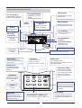
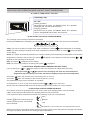
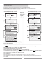
USER MANUAL CONTROL OLT-1X English/03-2005 CONTENTS PAGE TERMINAL-THERMOSTAT INSTALLATION AND UNIT CONFIGURATION USER INTERFACE DESCRIPTION SELECTING UNIT OPERATING MODE AND SET-POINT PROGRAMMING ADJUSTMENT ALARM CODES UNIT PROTECTION DEVICES 1 2 3-4 5 6 6 Your new LENNOX Thermostat has been designed to provide accurate control and display of room temperature. In addition, it will also display all relevant information pertaining to your system. The clearly marked buttons and informative display make it extremely easy to understand and simple to use. Please take a few moments to read the brief instructions and familiarise yourself with the various functions in order to obtain maximum benefit from this truly unique electronic control. This electronic control is organised into two integrated systems: a terminal, installed in the room, and a power board for managing the actuators in the electrical panel. The terminal is connected to the power board using a four-lead cable, thus greatly simplifying installation, with shield cable (supplied with the unit). IMPORTANT Prior of making the electrical connections, set the switch for heat pump unit or for cooling only unit. NOT USED FOR CASSETTE UNITS. (See documentation for the unit) COOLING ONLY (factory setting) This unit is valid for operating as a cold only or heat pump application. The unit should be configured prior to making the electrical connections, by setting the configuration switch as follows: J_MODE HEAT PUMP J_MODE J_MODE P.C.B. TERMINAL-THERMOSTAT INSTALLATION For correct installation the following warnings must be heeded: Always disconnect the power supply before performing any operations on the board during assembly, maintenance or replacement. The terminal should be fastened to the wall vertically, allowing for air to circulate through the instrument's vent-holes, in order to detect the correct ambient temperature Avoid places where the measurement of the ambient temperature by the internal sensor may be altered, such as outside walls, near doors leading outside, in direct sunlight, etc. INSTALLATION GUIDE FOR CONTROL CABLE (TO AVOID INTERFERENCES): Use the screened 15 m cable supplied with terminal (3 wires + screen). Wire the cable separated from electrical power wiring by a physical distance of 500 mm. Wire the cable separated from halogen lamps/fluorescent tube lighting... by a physical distance of 500 mm. Wire the cable separated from radio frequency sources such as radio transmitter... at least 500 mm. NEVER WIND THE REMAINING CABLE AROUND, CUT THE CABLE BY THE TERMINAL END. TERMINAL INSTALLATION The installation procedure is as following: 1º To detach the front panel of the terminal from the rear shell, insert a flat-head screwdriver in the slot in the centre of the bottom of the box and release the locking flap. 2º Raise the front panel using a hinge movement, using the upper edge of the instrument as the pivot and raising the lower edge. 3º To fasten the rear part of the box to the wall, use the mounting holes on the shell. 4º Connect the cables to the terminals on the electrical box, as indicated in electrical diagram. AUTO SLEEP DRY AUTO COOL HEAT FAN SWING KEY LOCK MON TUE WED THU FRI SAT SUN TIMER ACTIVE SET TIMER SET CLOCK COOL TEMP. HEAT TEMP. ROOM TEMP. ON / OFF SLEEP SWING FAN MODE ON TIMER OFF TIMER DAY HOUR SET TEMP Cable supplied with the unit Maximum length allowed is 15m 2 ON / ON / OFF OFF Sub-base Terminal-Thermostat UNIT Power board CLOCK HOLD 1 MINUTE 5º Finally, close the instrument, moving the front panel onto the rear shell with a hinge movement, in the opposite way as used for opening. First the long side of the front panel near the display is snapped onto the rear shell, then the opposite side, being careful that the terminal pins slide into their corresponding female terminals. 1 USER INTERFACE DESCRIPTION Key Lock Display Fan Speed Display Display indicates when key lock function is activated. Displays the fan speed setting. (Auto/High/Medium/Low) Sleep Display Display the sleep / energy saving status. Operation Mode Display Alarm indicator Displays the current mode of operation. Current Time Display Display the current time Display the temperature in °C or °F. AUTO SLEEP DRY AUTO COOL HEAT FAN SWING KEY LOCK Set Temperature or Room Temperature Display MON TUE WED THU FRI SAT SUN TIMER ACTIVE SET TIMER SET CLOCK ROOM TEMP. ON / OFF Indicates we are setting the clock Sleep button Fan button Press SLEEP button to activate the sleep or energy saving mode. Press FAN button to select Auto, High, Medium or Low fan speed. Swing button Press SWING button to activate the air sweep function. Clock Press MODE button to select operation mode from Cool, Heat, Auto, Dry and Fan. Pressing them the display shows the set point or the room temperature, and with them we can select the desired temperature (setpoint) SLEEP FAN MODE SWING ON TIMER OFF TIMER HOLD CLOCK DAY SET TEMP HOUR Minute button MINUTE When the control is in set clock or set timer mode, pressing the MINUTE button will change the set minute. Hour button Day button When the control is in set clock or set timer mode, pressing the DAY button will change the set day. Mode button Temperature button Hold button To adjust the actual real time Display the set or room temperature. On/Off Status Lamp Display Indicates that a programming is setting To resume the timer setting after the timer has been placed on hold Display the air swing status, (if incorporated on the unit) °C or °F Display Start / Stop Time Display Display the start and stop time programmed. Swing Display ON TIMER/OFF TIMER button Used to adjust an ON/OFF TIMER to the unit 2 When the control is in set clock or set timer mode, pressing the HOUR button will change the set hour. SELECTING UNIT OPERATING MODE AND SET-POINT TEMPERATURE A ) HOW TO TURN ON/OFF THE UNIT Operating Lamp On / Off AUTO TIMER ACTIVE Starting operation: When the unit is off, press the ON/OFF button. The operation LED lights and the unit will be turned on. Stopping operation: When the unit is on, press the ON/OFF button. The operation LED is extinguished and controls are turned off. SLEEP DRY AUTO COOL HEAT FAN SWING KEY LOCK MON TUE WED THU FRI SAT SUN SET TIMER SET CLOCK COOL TEMP. HEAT TEMP. ROOM TEMP. ON / OFF B) SELECTING THE UNIT'S OPERATING MODE The operating mode is always indicated on the display Pressing the mode button repeatedly you can change the unit operating mode, and choose the one desired: Cool Heat Auto Dry Fan COOL: The unit is working on cooling mode, when compressor is working symbol will appear on the display HEAT: The unit is working on heating mode, when compressor or electrical heater is working symbol will appear on the display AUTO: The system automatically switches from cooling to heating mode, depending on the position of the ambient temperature in respect to the set-point, the symbol will appear on the display and also the symbols or depends on the operating mode selected DRY: The symbol will appear on the display FAN: Fan control only; when fan is working the symbol will appear C) SELECTING DESIRED ROOM TEMPERATURE (SET-POINT) If unit is working, the SET TEMP or buttons allow to select the desired room temperature (set-point) When the button or are pressed one, the display will show the selected desired temperature (set-point) during 5 seconds, after that the display will show the room temperature SET TEMP The button allow the increase of the current set-point by 1ºC/1ºF The button allow the decrease of the current set-point by 1ºC/1ºF The temperature range is from 16ºC/60ºF to 30ºC/85ºF SET TEMP To change from ºC to ºF or vice versa, press the buttons SET TEMP y at the same time NOTE: If we have selected FAN as the unit operating mode, the SET POINT can not be modified D) SELECTING THE FAN OPERATING MODE To be able to select a fan operating mode, cool, heat or auto unit's operating mode must be selected. If DRY mode have been selected the fan operating mode can not be selected. If Fan mode have been selected the automatic fan operating mode can not be selected HIGH Pressing button scrolls through the following modes, and we can selected the one desired MEDIUM FAN LOW AUTO AUTOMATIC: The fan selects the most appropriated fan speed NOTE: Even when a low speed have been selected on heating mode, the unit self protective changing automatically to a higher fan speed, when the unit is working at high temperatures. 3 SETTING THE TIMER Our electronic climate control with timer operation is a programmable terminal. With this terminal you can program the unit to stop and start on each of the 7 days of the week. The ON TIMER and OFF TIMER functions may be combined. To set the timer, follow the instructions given below: PROGRAMMING THE UNIT TO START (ON TIMER) 1 Press the ON TIMER button. The and symbols will flash on the screen. SET TIMER button, select the With the DAY day of the week that you wish to program. Any previous settings will be displayed. 2 3 Mo (Monday) Tu (Tuesday) We (Wednesday) Th (Thursday) Fr (Friday) Sa (Saturday) Su (Sunday) PROGRAMMING THE UNIT TO STOP (OFF TIMER) 1 2 With the and buttons, MINUTE HOUR enter the exact time at which you wish the unit to start. The symbol will flash. 3 SET TIMER With the button, select the DAY day of the week that you wish to program. Any previous settings will be displayed. With the and buttons, MINUTE HOUR enter the exact time at which you wish the unit to stop. The symbol will flash. TIMER ACTIVE TIMER ACTIVE Push the DAY button to finish the programming for that day and to program a different day. Push the DAY button to finish the programming for that day and to program a different day. 4 Press the OFF TIMER button. The and symbols will flash on the screen. 4 Push or wait 15 seconds ON TIMER for the programming to be accepted, after which the symbol will remain visible and the clock will show the real time. Push or wait 15 seconds OFF TIMER for the programming to be accepted, after which the symbol will remain visible and the clock will show the real time. TIMER ACTIVE TIMER ACTIVE With the ON TIMER function, the unit will automatically start at the selected time, in the same operating mode as when it was switched off. NOTE: If the TIMER ACTIVE symbol does not remain visible on the screen, the control has not stored the settings. HOW TO DEACTIVATE THE ON TIMER / OFF TIMER FUNCTION To deactivate the settings and store them for future use: Press the button for 3 seconds, until the indication disappears. HOLD To activate them once again, press the button for 3 seconds once again, until the TIMER ACTIVE HOLD TIMER ACTIVE indication appears HOW TO DELETE THE ON TIMER / OFF TIMER FUNCTION Push the button. Push the button and select the day of the week that you wish to delete from the settings. Push the button as many times as necessary until - : - - appears, showing that the setting for that day has been deleted. ON TIMER DAY HOUR 4 OPERATING HOUR ADJUSTMENT Press button CLOCK once to set the clock mode, the indication Press button DAY Press button HOUR Press button Press button MINUTE CLOCK SET CLOCK will appear on the display blinking repeatedly, scrolls through the following days of the week, and we can selected the one desired to set the hour MON TUE WED THU FRI SAT SUN to set the minutes to accept The unit is supplied with a lithium battery acting as a power back up in the case of a power failure. The real time clock and other settings are maintained during the power failure and reset when power is restored. SLEEP Pressing the button , we activate this function. It is registered on the display with the symbol SLEEP SLEEP COOLING MODE HEATING MODE ºC Set Point+2ºC Set Point 0.5 1 2 HOURS Set Point - 0.5ºC Set Point+1ºC Set Point - 1ºC Set Point+0.5ºC Set Point 0.5 1 2 Set Point - 2ºC HOURS ºC SLEEP FUNCTION ON Decrease the set point temperature as the above drawing shows SLEEP FUNCTION ON Increase the set point temperature as the above drawing shows FUNCTION SWING Press button SWING , the function swing gets activated, the symbol SWING will appear on the LCD display KEY LOCK This feature protects the controls from being tampered with by children or unauthorized persons. To activate, press the MINUTE button three times consecutively, KEY LOCK symbol will appear on the LCD display. During this time, only button can be used. To cancel this feature, press the button again three times consecutively. and the indication KEY LOCK will MINUTE disappear on the display ON / OFF 5 ALARM CODES The unit self-protect through safety devices, when any of these safety devices detect an anomaly, shown in the display in order to advise the installer. The activation of an alarm brings about: - The display of the alarm code on the display. - The blocking of some or all the outputs, depending on the type of alarm. VIS (Visualization): Indicates the type of alarm shown on the display. RE (Reset): Type of reset: AUT: AUTOMATIC RESET: Some alarms are automatically reset, when the cause is no longer present, they disappear from the display. MAN: MANUAL RESET: Press "ON/OFF" button. VIS. DESCRIPTION Ambient temperature regulation probe error. Indoor coil temperature probe error. EFFECTS Unit will stop Compressor will stop ACTION Check connections between unit and thermostat. AUT Check connections of indoor coil temperature probe. AUT These protections are automatic reset for the first time. To reset for second time press button "ON/OFF" until alarm disappears. If the alarm shows up again, check: Connections of indoor coil temperature probe. Indoor unit works properly. Clean air filters. Compressor These protections are automatic reset, the alarm resets automatically when there is no more water. will stop. Condensate If the alarm shows again, check the water drain, and the pump working. connections of float switch. Compressor overload. During heating cycle the indoor Compressor coil temperature has been too will stop high. Overflow of water condensing. The float switch has detected water overflow. RE AUT/ MAN AUT Short circuited temperature probe. Unit will stop Check probe connection. AUT Temperature probe open. Unit will stop Check probe connection. AUT WARNINGS VIS. DESCRIPTION Probe temperature lower than 8ºC. Probe temperature higher than 37ºC. EFFECTS The unit is working, and the warning disappears when temperature is between 8ºC and 37ºC. UNIT PROTECTION DEVICES AGAINST FREQUENT COMPRESSOR CYCLING When COOL/HEAT/AUTOMATIC is selected, the start up of the unit will be delayed for 3 minutes, to protect the unit against frequent compressor cycling. AIR PREHEATING On heat mode, the indoor unit fan will not start or will start at low speed, to prevent from air cool feeling, until the indoor unit temperature reaches the set temperature then the unit will operate to the selected temperature. DEFROST CYCLE When the unit is operating on heating mode, the unit will do defrost to eliminate the ice that will produce the outdoor unit; on this cycle, the indoor unit fan switches off. AUTO RESTART If power failure occurs during operation, the unit will start in the same operation mode as before after power recovery. FREEZE-UP PROTECTION If the unit is operating on cooling only mode, and the indoor unit coil temperature is below a set value, the unit stops. DETECTING BROKEN SENSOR If the control system detects a sensor reading out of permissible deviation, the unit stops. 6 www.lennoxeurope.com BELGIUM, LUXEMBOURG : CZECH REPUBLIC : FRANCE : GERMANY : IRELAND : NETHERLANDS : POLAND : PORTUGAL : RUSSIA : SLOVAKIA : SPAIN : UKRAINE : UNITED KINGDOM : OTHER COUNTRIES : COD: MUL30E-0303 03-2005 LENNOX BENELUX N.V./S.A. www.lennoxbelgium.com LENNOX JANKA a.s. www.janka.cz LENNOX FRANCE www.lennoxfrance.com LENNOX DEUTSCHLAND GmbH www.lennoxdeutschland.com LENNOX IRELAND www.lennoxireland.com LENNOX BENELUX B.V. www.lennoxbenelux.com LENNOX POLSKA Sp. z o. o. www.lennoxpolska.com LENNOX PORTUGAL Lda. www.lennoxportugal.com LENNOX DISTRIBUTION MOSCOW www.lennoxrussia.com LENNOX SLOVENSKO s.r.o. www.lennoxdistribution.com LENNOX REFAC S.A. www.lennox-refac.com LENNOX DISTRIBUTION KIEV www.lennoxrussia.com LENNOX UK www.lennoxuk.com LENNOX DISTRIBUTION www.lennoxdistribution.com Due to Lennox's ongoing commitment to quality, Specifications, Ratings and Dimensions subject to change without notice and without incurring liability. Improper installation, adjustment, alteration, service or maintenance can cause property damage or personal injury. Installation and service must be performed by a qualified installer and servicing agency.