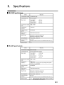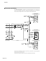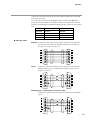
1
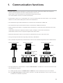
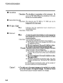
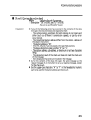
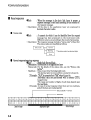
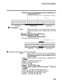
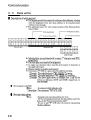
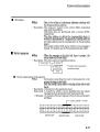
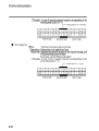
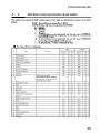
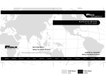
No. CP-UM-1583E DIGITRONIK CPL COMMUNICATION SDC40A/40G User's Manual Thank you for purchasing the SDC40A /40G. This manual contains information for ensuring correct use of the SDC40A /40G. It also provides necessary information for installation, maintenance, and troubleshooting. This manual should be read by those who design and maintain devices that use the SDC40A/40G. Be sure to keep this manual near by for handy reference. RESTRICTIONS ON USE This product has been designed, developed and manufactured for general-purpose application in machinery and equipment. Accordingly, when used in applications outlined below, special care should be taken to implement a fail-safe and/or redundant design concept as well as a periodic maintenance program. • Safety devices for plant worker protection • Start/stop control devices for transportation and material handling machines • Aeronautical/aerospace machines • Control devices for nuclear reactors Never use this product in applications where human safety may be put at risk. REQUEST Ensure that this User's Manual is handed over to the user before the product is used. Copying or duplicating this User's Manual in part or in whole is forbidden. The information and specifications in this User's Manual are subject to change without notice. Considerable effort has been made to ensure that this User's Manual is free from inaccuracies and omissions. If you should find any inaccuracies or omissions, please contact Yamatake Corporation. In no event is Yamatake Corporation liable to anyone for any indirect, special or consequential damages as a result of using this product. 1994 Yamatake Corporation ALL RIGHTS RESERVED The DIGITRONIK® is a registered trademark of Yamatake Corporation. Windows ®, Windows NT ® and Microsoft ® are registered trademark of Microsoft Co.,Ltd. Other company names and product names listed in this manual are registered trademark or trademark of respective companies. The Role of This Manual In all, 2 manuals have been prepared for the SDC40A Read the manual according to your specific requirements. The following lists all the manuals that accompany the SDC40A and gives a brief outline of the manual: If you do not have the required manual, contact Yamatake Corporation or your dealer. Digitronik Line SDC40A Digital Indicating Controller User's Manual No.CP-SP-1043E The manual is provided with SDC40A. People who are involved in hardware design to build the SDC40A into a control panel and maintenance must read this manual. This manual describes the outlines of hardware and controllers, installation/wiring, maintenance/checking, troubleshooting measures and the hardware specification. DIGITRONIK CPL COMMUNICATION SDC40A/40G User's Manual No.CP-UM-1583E This manual is required reading for those using the CPL communications functions of the SDC40A. This manual describes an outline of CPL communications, wiring, communications procedures and SDC40A communications data, how to remedy trouble, and communications specifications. 1. Communication functions • In the RS-232C system, this instrument is connected with one master station (also called a host computer as which a personal computer or the like is used) in the form of one to one. In this system, only one instrument can communicate with the master station. The "station address" must be set to make communication. • In the RS-485 system, up to 31 instruments (see *1) can be connected with one master station. The “instrument addresses” are then used to identify mate stations for communication • The communication procedure and format are in common to the both RS-232C and RS-485. • The communication protocol and format conform to the RS-232C and RS-485 interfaces. • When the following procedure is completed during communication, various data for the instrument can be read or written. (1)The master station (host computer) transmits a request message to a slave station (instrument) (2)The master station receives a response message from the slave station. • Instructions from master station to slave station are classified into two types; “read” and “write”. • The type of ready/write data can be optionally selected by “data address”. • CPL (Controller Peripheral Link) communications network is the Yamatake Corporation's host-communications. RS-232C connection example RS-485 connection example Master station RS-232C RS-485 connection example Master station RS-232C RS-232C RS-232C/RS-485 converter RS-485 (5-wire system) Slave station Connection between master station and slave station Master station Slave station CMC10L001A000 (*2) RS-485 (3-wire system) Connection between master station and slave station Slave station • The high-performance communication controller CMC410A102 is available for conversion between the RS232C and RS-485 interfaces. (*1) When the master station is an MA500 DIM or CMC410, it can be connected to up to 16 slave stations. (*2) The CMC10L001A000 communication controller is an RS-232C/RS-485 (3-wires type) converter available from Yamatake Corporation. 1-1 2. Wiring 2 - 1 RS-232C Connection The DIGITRONIK instrument with the RS-232C communication function is wired for communication as shown below. ● Connection with the master station in the form of 1 to 1. This instrument is provided with three communication terminals (RD, SD, and SG). Data may not be output unless the other kind terminals of the master station side RS232C interface are short-circuited as shown in the figure below. Usually, the pin array of the RS-232C connector of a personal computer, or the like is as shown below (Terminal mode). In a rare case, pins (2) and (3), (4) and (5), and (6) and (20) may be replaced with each other, respectively (MODEM mode). Check the RS-232C pin array by referring to the instruction manual for the host computer. RD SD SG RS CS DR CD ER SD 2 3 RD 5 SG 7 8 6 1 4 Host computer (master station) DIGITRONIK instrument (slave station) Example of connection using Yamatake Corporation CBL232FNZ02 Note Cable catalog No. : CBL232FNZ02 (2m cable for RS-232C, 9-pin, D-Sub socket, contact - crimp style terminal) ● RS-232C connector signals (9 pins) Example: IBM and compatibles Pin No. JIS Code Name Signal Direction Host-station 1 CD DCD ← 2 RD RxD ← 3 SD TxD → → 4 ER DTR 5 SG GND 6 DR DSR ← 7 RS RTS → 8 CS CTS ← (25 pins) Example: PC-9800 Series Pin No. JIS Code Name Signal Direction Host-station (14 pins) Example: PC-9821Ne Pin No. JIS Code Name Signal Direction Host-station 1 — FG 1 RD RxD ← 2 SD TxD → 2 DR DSR ← 3 RD RxD ← 3 CD DCD ← RTS → 4 CS CTS ← 4 RS 5 CS CTS ← 9 SD TxD → 6 DR DSR ← 10 RS RTS → 7 SG GND 11 ER DTR → 8 CD DCD ← 13 SG GND 20 ER DTR → 14 SG GND 2-1 2. Wiring 2-2 RS-485 Connection ■ 5-wire system When the DIGITRONIK instruments with the communication functions in compliance with the RS-485 are used in the 5-wires system, they are connected, for example, as follows: Terminating resistor Terminating resistor Shielded cable Master station 5-wire system DIGITRONIK instrument (slave station) SDA SDB RDA RDB SG FG RDA RDB SDA SDB SG FG Shielded cable 5-wire system DIGITRONIK instrument (slave station) SDA SDB RDA RDB SG Shielded cable Terminating resistor Terminating resistor FG 5-wire system DIGITRONIK instrument (slave station) SDA SDB RDA RDB SG FG Connect two terminating resistors of 150Ω 5%, 1/2W min. to the instrument at each end of the transmission line. Also connect the shield wires to FG at one place. In the 5-wires system, the Yamatake Corporationl CMC10L can be used as a converter in the master station. It can also be used as a converter in the slave station when the number of the slave stations is only one, but cannot be used as a converter in a slave station when two or more slave stations are used. 2-2 2. Wiring ■ 3-wire system The DIGITRONIK instruments with the communication functions in compliance with the RS-485 can also be used in the 3-wires system. An example of connection methods in such a case is shown below. !" # $% & ' !" # $% & !" # $% & Connect one terminating resistor of 150Ω 5%, 1/2W min. to the instrument at each end of the transmission line. Also connect the shield wires to FG at one place. In the 3-wires system, the Yamatake Corporation CMC10L cannot be used as a converter in the master station or slave station. In an instrument equipped with only three RS-485 terminals, the asterisked (*) wiring is done internally. 2-3 6. Communication for master station ■ Precautions for programming • The longest response time of the instrument is 2sec. Therefore, the response monitor time should be set to 2sec. • If no response is obtained within 2sec, retransmit the same message. When no response remains coming even after making retransmission twice, it should be regarded as a communication error. • The above-mentioned retransmission is required since a message may not be properly transmitted due to noise or the like during communication. Note When the device distinction codes "X" and "x" are used alternately during message retransmission from the master station, the received response message can be conveniently identified to be the latest message or preceding one. 6-1 Appendix ■ Connection with CMC10L The CMC10L001A000 is available as an RS-232C/RS-485 (3-wire system) converter from Yamatake Corporation. The following diagram shows an example of wiring using a straight cable for a host computer in the terminal mode: 5-wire system DIGITRONIK instrument (slave station) SDA Terminating resistor SDB * * RDA RDB SG FG Shielded cable RD SD DA MOD. 2 2 3 3 DB TER. MOD. TER. RS 7 7 8 8 6 6 5 5 ER 4 4 CD 1 1 CS DR SG SG Shielded cable 3-wire system DIGITRONIK instrument (slave station) DA DB SG Host computer FG Shielded cable CMC10L 5-wire system DIGITRONIK instrument (slave station) SDA SDB Terminating resistor * * RDA RDB SG FG Connect two terminating resistors of 150Ω±5%, 1/2W min. to the instrument at each end of the transmission line. Conduct the wiring externally for the wires marked with an asterisk. Appendix-2 Appendix Connect the master station SD to the slave station RD, and the master station RD to the slave station SD. To execute this connection, set the MODE switch provided in the CMC10L as shown in the following table in accordance with the host computer side RS-232C connector pin arrangement (modem/terminal) and the type of cable (cross/straight) used: RS-232C Cable type MODE switch TERMINAL Straight MODEM TERMINAL Cross TERMINAL MODEM Straight TERMINAL MODEM Cross MODEM ● RS-232C cable Straight: An RS-232C cable with a D-Sub (9-pin) connector at each end where pins with the same number are mutually connected (for example, pin (2) to pin (2), and pin (3) to pin (3)) +, 4, 5, -4 5/ ,4 45 +5 Cross: ! " # $ % & ! " # $ % & +, 4, 5, -4 5/ ,4 45 +5 An RS-232C cable with a D-Sub (9-pin) connector at each end where different number pins are connected (for example, pin (2) to pin (3), and pin (3) to pin (2)) 4, 5, 45 +5 ,4 -4 +, 5/ ! % & $ " # ! % & $ " # 4, 5, 45 +5 ,4 -4 +, 5/ D-Sub (25-pin) – D-Sub (9-pin) conversion cable: An RS-232C cable for conversion between D-Sub (25-pin) and D-Sub (9-pin) ./ 5, 4, 45 +5 ,4 -4 +, 5/ ! " # $ & % ! % & $ " # 5, 4, 45 +5 ,4 -4 +, 5/ Appendix-3 Revision History Printed Date Manual Number Edition 94-06 98-10 CP-UM-1583E 1st Edition 2nd Edition 2-1 8-1 01-05 3rd Edition 03-06 4th Edition Revised pages Description RS-232C communication cable has been changed. Baud rate to Transmission speed Character synchronization method to Synchronous method Positioning of this Format changed CP-UM-1580E-A4 deleted instruction manual 1-1 CMA50A105 to CMC10L 2-1 to 2-4 RS-232C and RS-485 connection diagrams Appendix2 to 3 changed. 4-14 Deleted CMA50 from the explanation 5-5, 5-16 No10:MV of contents added 5-29 (2)Status 2 write deleted 6-2 to 6-5 Sample program deleted Appendix4 Page deleted RESTRICTIONS ON USE changed. 1-1 Changed description of the CPL communications. 2-1 Conversion connector part No:81408811-001 deleted 4-3 The character codes of a check-sum was corrected 35H,5 to 41H, A. 4-4 The character codes of a check-sum was corrected 7BH to 76H, 85H to 8AH, 8A to 8H, 35H to 41H. 7-1 Explanation of No. 2 was clarified. Appendix3 RD and SD of a straight cable and crossing cable were replaced. Specifications are subject to change without notice. Advanced Automation Company International Business Headquarters Totate International Building 2-12-19 Shibuya Shibuya-ku Tokyo 150-8316 Japan URL: http://www.yamatake.com This has been printed on recycled paper. (01) Printed in Japan. 1st Edition: Issued in June, 1994 4th Edition: Issued in June, 2003(M)