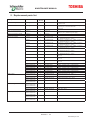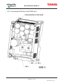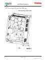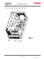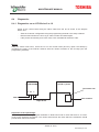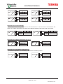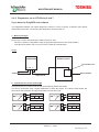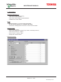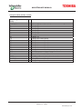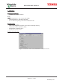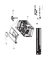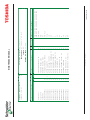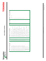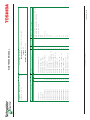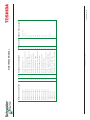
1
MAINTENANCE MANUAL
MAINTENANCE MANUAL - CONTENTS
Altivar 38
1. General
1.1
1.2
1.3
1.4
1.5
Objective
Products concerned
Product design and manufacture
Exchange and repair
Assistance
2. Required skills - training
2.1 Required skills
2.2 Training
3. Documentation
3.1
3.2
3.3
3.4
Catalogue
User’s manual
MIT Intranet
Vantive RGSA (Return Good Service Agreement)
4. Repair service equipment
4.1 Equipment
4.2 Dialogue and diagnostics tool
4.3 Test bench
5. Replacement parts list
6. Software
6.1
6.2
6.3
6.4
6.5
6.6
6.7
6.8
6.9
6.10
6.11
6.12
6.13
ATV38 drive software
Operator terminal software
AI I/O extension board software (VW3A58201)
PG I/O extension board software (VW3A38202)
Fipio card software (VW3A58301)
Modbus Plus card software (VW3A58302)
Interbus-S card software (VW3A58304E)
AS-i card software (VW3A58305)
Unitelway / Modbus / Jbus card software (VW3A58303)
Profibus-DP card software (VW3A58307)
Can Open card software (VW3A58308)
Devicenet card software (VW3A58309)
Ethernet card software (VW3A58310)
Section - 1/2
efesotomasyon.com
MAINTENANCE MANUAL
7. Installation diagnostics
7.1
7.2
7.3
7.4
7.5
7.6
"The speed is unstable"
"Motor turning the wrong way"
"Motor overheating"
"Motor accelerating too slowly"
"Poor control of motor stopping or deceleration"
"The motor does not start"
8. Help with troubleshooting
8.1
8.2
8.3
8.4
8.5
8.6
Preamble
Block diagram of the power circuits
Connecting the DC bus
Diagnostics
Faults that may be displayed
Troubleshooting based on the fault displayed
9. Changing the faulty component - drawings - parts lists
9.0
9.1
9.2
9.3
9.4
9.5
9.6
9.7
9.8
9.9
Safety instructions and precautions
ATV38 Size 2
ATV38 Size 3
ATV38 Size 4
ATV38 Size 5
ATV38 Size 6
ATV38 Size 7
ATV38 Size 8
ATV38 Size 9
ATV38 Size 10
10. Procedure for validation after repair
10.1 ATV38 sizes 2 to 10
10.2 Quality reporting to the VSD division
Section - 2/2
efesotomasyon.com
MAINTENANCE MANUAL
1.
General
1.1
Objective
This document defines the policy and methods to be put in place in each country-based
organization for repairing the Altivar 38 locally.
Repairs are carried out using replacement parts supplied by SCHNEIDER. This comes solely
within the framework of the “service agreement”. Once this agreement has been signed, a
country will have a local representative responsible for this offer.
1.2
Products concerned
Product coding:
Eg: ATV38HD28N4(X)
Name
Type
Rating
Voltage
…
ATV38
H: heatsink
D28
N4: 380/460 V
X: without EMC
Size
T2
T3
T4
T5
T6
T7
T8
Motor power in KW
0.75
1.5
2.2
3
4
5.5
7.5
11
15
18.5
22
30
37
45
55
75
90
Reference
ATV38HU18N4
ATV38HU29N4
ATV38HU41N4
ATV38HU54N4
ATV38HU72N4
ATV38HU90N4
ATV38HD12N4
ATV38HD16N4
ATV38HD23N4
ATV38HD25N4(X)
ATV38HD28N4(X)
ATV38HD33N4(X)
ATV38HD46N4(X)
ATV38HD54N4(X)
ATV38HD64N4(X)
ATV38HD79N4(X)
ATV38HC10N4X
Section 1 - 1/3
efesotomasyon.com
MAINTENANCE MANUAL
Size
T9
T10
1.3
Reference
Motor power in KW
110
132
160
200
220
250
280
315
ATV38HC13N4X
ATV38HC15N4X
ATV38HC19N4X
ATV38HC23N4X
ATV38HC25N4X
ATV38HC28N4X
ATV38HC31N4X
ATV38HC33N4X
Product design and manufacture
All the modules, accessories and software are designed and developed by Schneider Electric
or in collaboration with their associates.
At all stages of design and manufacture, the products are handled with great care. The
products are subject to continuous monitoring in order to achieve a high level of quality.
1.4
Exchange and repair
The Altivar 38 is a Category 4 repairable product for the SBS:
–
local repair for country-based organizations that have signed the service agreement
–
repair at the factory for other country-based organizations
The purpose of this document is to help you repair these products.
cl ient
produits
défecteux
produits
reparés
APV4
produi ts
défecteux
agence pays
produits
reparés
échange standard
CTA local
SRES
échange standard
de sous-ensembl es
usine
For repair at the factory or for expert advice, consult the Intranet site:
HTTP://139.160.73.11/portailDAS/ci.nsf (“Technical support and Training/About support/What
to do” menu)
Section 1 - 2/3
efesotomasyon.com
MAINTENANCE MANUAL
Reminder of after-sales categories:
• APV2
After-sales category 2: Non-repairable drive.
• APV4
After-sales category 4: repairable drive. These are identified in the product file by a code with
the suffix TA. The stated price corresponds to the repair cost if the product is returned to the
factory (net price).
1.5
Assistance
1.5.1 Work carried out on site
The customer will be provided with on-site assistance by technicians and engineers from the
SCHNEIDER service teams in the customer’s country.
1.5.2 Technical support
The first level of technical support is provided by the level 1 and 2 forums that the customer
can access.
The third level of technical support is provided by the Schneider Vantive intranet: vantive selfservice (HTTP://139.160.73.11/Services/IServices4.nsf) or in emergencies call the Global Help
Desk direct line:
Tel:
+33 (0)1 41 39 39 00
Fax:
+33 (0)2 32 78 11 64
1.5.3 Customer returns
Faulty equipment (complete products or sub-assemblies) may be returned according to the
terms of the SCHNEIDER warranty policy.
When returning products, complete and attach the form below. This form will shortly be
available on the Intranet.
1.5.4 Updating the installed base
If there is a major fault or new functions have been added, it may be necessary to update the
products.
In this case, advice will be sent to all the SCHNEIDER networks.
Section 1 - 3/3
efesotomasyon.com
s
Product Failure Description
Made the
by
Agency/Official distributor :
Customer name :
This sheet is associated with case VANTIVE N°
Yes
Was this drive already repaired for preventive maintenance :
No
Yes
or a commercial gesture ?
No
PRODUCT CHARACTERISTICS
Soft version :
Reference :
Quantity :
Install. date :
Serial number :
Option board :
Soft version :
Serial number :
Other options :
CUSTOMER APPLICATION
Fan
Winder
Pump
Hoisting
Convoyor
Packing
Other machine :
MOTOR CHARACTERISTICS
Asynchronous motor
Slip rings motor
Parallel motors
How many
Shielded cable
Other motor :
Nominal Power kW =
Motor voltage en V =
Nominal speed tr/mn =
Motor current A =
Dephasing Cos Phi=
Frequency Hz =
Motor Coupling
Cable length
Encoder type
SUPPLY
Frequency min/max =
Measured voltage min/ma
TT
Neutral regime
IT
TN
FAILURE DESCRIPTION
When does the failure appear ?
At the first
On a new machine
Permanent fault
Intermitent fault
After a machine retrofit
During adjusment
During working
Frequency :
drive working time per day
Ambiant temperature °C :
IMPORTANT: Precise in what environment is the drive, who did observe the failure, the state and the eventual modifications of the
installation, when did the failure happen in the sequence (Acc, Dec, speed, load etc..), the nature of the eventual bad conformity ? Joint the
setting file (Powersuite, PC software), the list of the past fault in memory, diagram, and photos if necessary.
FIXING OF THE FAILURE
Yes
Did you change the drive ?
No
by an other, witch one
by the same
Did you change a part in the drive ?
Yes
No
After changing did you solve the problem ?
Yes
No
Witch one
Thanks to return this document to GHD or attach it with your Vantive case
Tél : +331 41 39 39 00
mailto:[email protected]
efesotomasyon.com
MAINTENANCE MANUAL
2. Required skills - Training
2.1
Required skills
An Altivar should be repaired by technicians with the following experience:
–
Knowledge of the operation of rotating machines driven by electronic variable speed
drives
–
Principle of power switching and electronic control
–
In-depth knowledge of the following tools: PCs, oscilloscopes, multimeters, etc.
For the protection of equipment and personnel, the qualified maintenance technician should
implement the procedure detailed in this manual.
2.2
–
Read, interpret and follow the instructions and precautions described in this manual as
well as in other reference material
–
Use the necessary tools in a professional manner
Training
ATV38 training is included in the ATV58 training courses.
2.2.1 Customer training
The I.S.F. (Schneider Training Institute) organizes training courses on variable speed drives
for people to become familiar with these products and learn how to install them.
For further information, please contact the I.S.F:
Tel: +33 (0) 1 41 39 60 00
E-mail: schneiderformation.com
Fax: +33 (0) 1 41 39 60 72
2.2.2 Internal training
Several courses concerning selection and setup of variable speed drives are available.
Descriptions of their content are attached to this document.
For further information, please refer to the IC SBS training guide.
2.2.3 After-sales training
This course is reserved for Schneider personnel working on-site. It requires a good knowledge
of the product as well as associated applications (cooling, pumping, etc).
For further information, please contact the IC SBS training representative.
2.2.4 Training support
Training support is available on:
• Intranet:
Connect via the IC SBS server. (HTTP://139.160.73.11/PortailDAS/ci.nsf) "Technical support
and training" menu
• CDROM labelled "CIFOR"
To be ordered from Schneider Comm. Services - Meylan / France
Tel:
Fax:
+33 (0)4 76 60 59 17 or +33 (0)4 76 60 59 02
+33 (0)4 76 60 67 32
Section 2 - 1/3
efesotomasyon.com
MAINTENANCE MANUAL
*
*
*
*
*
*
*
Section 2 - 2/3
efesotomasyon.com
MAINTENANCE MANUAL
ATV 58 EXPERT
Training
objectives
To become an expert in
setting up Altivar 58 drives
(0.37 to 55 kW)
COURSE CONTENT
·
·
·
·
·
·
·
·
Range
Technology
Performance
Protection
Customer terminals/sequences
Functionality
Options
Accessories
EXP58
1 day
DOCUMENTATION SUPPLIED
Required level of
expertise
ð
ð
ð
ð
ð
Knowledge of mechanical
principles involved
In-depth knowledge of power
electronics
Familiarity with asynchronous
motors
Familiarity with VSD products
Good hands-on experience
Altivar ATV58 training manual
Programming manual
COMMENTS
More complete variable speed drive than the Altivar 28, integrating numerous additional
functions for more complex applications.
Lectures: 70%
Practical: 30%
LOCATION: RUEIL GARE
PRICE: Free
EQUIPMENT USED
Altivar ATV58.
Section 2 - 3/3
efesotomasyon.com
MAINTENANCE MANUAL
3. Documentation
3.1
Catalogue
3.2
User's manual:
Different user’s manuals are available:
* French – English – German - Spanish
DESCRIPTION
ATV38 user’s guide
I/O extension board: VW3A58201
I/O extension board: VW3A58202
Pump option card: VW3A58210
REF
VVDED 302071
VVDED 397046
VVDED 397051
VVDED 398009
* French - English
DESCRIPTION
FIPIO communication card:
Modbus+ communication card:
Unitelway/Modbus/Jbus com. card:
Interbus-S com. card:
Interbus-S com. card
with separate 24V power supply
AS-I com. card
Profibus DP com. card
RS 485 connection kit
Internal communication variables
3.3
VW3A58301
VW3A58302
VW3A58303
VW3A58304
VW3A58304E
VW3A58305
VW3A58307
VW3A58306
REF
VVDED 397045
VVDED 397044
VVDED397054
VVDED 397053
VVDED397053
VVDED 397055
VVDED398008
VVDED 397057
VVDED 397058
M.I.T. Intranet
These are technical information sheets regarding VSD products (software versions,
application sheets, etc).
These documents can be consulted on the IC SBS Intranet site.
Address: HTTP://139.160.75.12/intramit2000/fr_vv/index.htm
Select: “MIT, Technical Information” – “VSD”
Section 3 - 1/2
efesotomasyon.com
MAINTENANCE MANUAL
3.4
Vantive RGSA (Return Good Service Agreement), formerly known as BEST
This database is accessed via the SCHNEIDER intranet.
• Industrial control site/technical support/help desk: HTTP://139.160.73.11/PortailDAS/ci.nsf
This database allows users:
–
To ask a specific question and receive a personalized response from the SBS
–
In country-based organizations, to consult their portfolio of current or answered questions,
whether or not the SBS is available
–
To search the database for all the questions that the SBS has already been asked in order
to find a possible suitable response or search avenue
Section 3 - 2/2
efesotomasyon.com
MAINTENANCE MANUAL
4. Repair service equipment
4.1
Equipment
List of tools required to repair ATV38 drives:
• General equipment
–
contact grease (Ref SCHNEIDER VY1A58856)
–
multimeter
• ATV38 Size 2 to 3
–
torx key 150 mm deep (Ref FACOM 80 TX 20)
or 6 mm flat screwdriver 150 mm long
• ATV38 Size 4 and 5
–
torx key 150 mm deep (Ref FACOM 80 TX 20)
or 6 mm flat screwdriver 150 mm long
–
size 3 Allen key (IPM and capacitors)
–
size 4 Allen key (SKIIP)
–
8 mm spanner (screwdriver bit preferable)
• ATV38 Size 6 and 7
–
screw driving machine 500 revs 1.5 to 3.9 Nm
or torque wrench 0.5 to 10 Nm
–
hexagon drive socket 8 across flat
–
hexagon drive socket 10 across flat + extension 150 mm and 80 mm
–
hexagon drive socket 12 across flat
–
hexagon drive socket 13 across flat 50 mm deep
–
size 20 torx key (ref. FACOM 80TX.20)
or size 20 torx shank bit + 150 mm extension for screw driving machine
–
hexagon shank bit 3 across flat
–
hexagon shank bit 4 across flat
–
hexagon shank bit 5 across flat
–
300 mm extension
For ATV38 Sizes 6 and 7, use of an electric screwdriver makes it significantly quicker to
assemble/dismantle the drive.
• ATV38 Size 8 and 10
–
crosshead screwdriver (3 types, including one 250 mm long for size 9)
–
flat screwdriver
–
13 mm spanner
–
17 mm socket wrench
–
17 mm spanner
–
flat pliers
Section 4 - 1/25
efesotomasyon.com
MAINTENANCE MANUAL
4.2
Dialogue and diagnostics tool
4.2.1 Dialogue tool
First-level diagnostics are obtained via the programming terminal or the setup software. These
tools are used primarily to:
–
Check the I/O states
–
Read the error log while displaying the operating phase during which the fault appeared
–
Save and transfer drive configurations
4.2.2 Diagnostic equipment for all ATV38 drives
A diagnostic kit is available, and can be ordered from Evreux quoting reference VZ3N5820. It
includes:
4.3
–
A ribbon cable which can be used to supply the control board from an ATV58HU18M2
without supplying the power
–
A circuit which can be connected to the control terminals in order to test the I/O
–
Diagnostic software to help you identify the faulty component(s) and test your repair
It performs the following functions:
• Testing the control board (power supply and I/O)
• Testing all power circuits
• Calibrating the power
Test bench
In order to test the Altivar 38 after repair, a document is attached showing how to build a test
bench. It corresponds to that used to test Altivar 66 and Altistart 48 drives. Only the cable
linking the Altivar 38 connectors to the 15-pin Sub-D connector is different.
Schematic diagram of this cable:
Section 4 - 2/25
efesotomasyon.com
CONSTRUCTION OF THE TEST PLATFORM
efesotomasyon.com
efesotomasyon.com
PAGE
CABINET-ATV66 CONNECTION
DOOR AND CABINET
OPERATING LEGEND
OPERATING LEGEND
CONTROL SEQUENCE
CONTROL SEQUENCE
CONTROL SEQUENCE
CONTROL SEQUENCE
POWER
RECAPITULATION PAGE
FLYLEAF
DESIGNATION
EVOLUTION INDEX
PAGE
DESIGNATION
efesotomasyon.com
EVOLUTION INDEX
CONTROL SEQUENCE SUPPLY
ON CONSOLE
DOOR
SUPPLY 380V TRIPHASE + NEUTRAL
PC1: ON CABINET
DOOR
SUPPLY 220 V TRIPHASE
ATV NETWORK SUPPLY
POWER
efesotomasyon.com
ATV OUTPUT SUPPLY
PC2: ON CABINET RIGHT SIDE
ATV MOTOR TEST BENCH
SWITCH ON
RUN
220 V
CONTROL
SWITCH ON
CONSOLE
STOP
EMERGENCY
STOP
SINGLEPHASE
OPERATION VALIDATION
RUN
380 V
POWER
STOP
SINGLEPHASE
RUN
POWER
SWITCH ON
TRIPHASE OPERATION
VALIDATION
TRIPHASE
RUN
VARIATOR
SECURITY
SHUNT
VARIATOR POWER
SWITCH ON
PLATFORM
STOP
RUN
380 V
VOLTAGE CHOICE
FOR PLATFORM SUPPLY
RUN
220 V
efesotomasyon.com
DEBUGGING
DEBUGGING
RELAY
INTERMEDIARY
RELAY
FORWARD
FORWARD
RELAY
BACKWARD
BACKWARD
RELAY
BRAKE
RELAY
efesotomasyon.com
ELECTRIC SUPPLIES
SINGLEPHASE
RUN
TRIPHASE
efesotomasyon.com
SUB D 56 PIN CONNECTION
ON CONSOLE FRONT SIDE
PC3
VIEW ON SEAM SIDE
S10: LOCKING-UNLOCKING SWITCH
VOLTMETER
ON CONSOLE FRONT SIDE
VOLTAGE
DIVIDER
efesotomasyon.com
BRAKE RESISTANCE
ON CONSOLE ROOF
REFERENCE
PAGE
COL
CONTACT BREAKER
PROTECTION MODULE
COIL 240 V 50 HZ
HANDLE + DRILL-PLATE
MOTOR CIRCUIT BREAKER
ADDITIONAL CONTACT START-STOP
EXTERIOR CONTROL
NEUTRAL FUSE SUPPORT
FUSE SUPPORT
FUSE CARTRIDGE aM
FUSE SUPPORT
FUSE CARTRIDGE gl
FUSE SUPPORT
FUSE CARTRIDGE aM
FUSE SUPPORT
FUSE CARTRIDGE aM
SINGLEPHASE TRANSFORMER
VOLTMETER
“BRAKING” LABEL
VOLTAGE DIVIDER
AMMETER 0-40 A
“MOTOR I” LABEL
INTENSITY TRANSFORMER
MARTIN LUNEL PLUG 16-25A
P17 CONNECTOR 16A 3P + E 380 V
PE BLANKING PLUG
AR TERMINAL (BRAKING R)
AR TERMINAL
AR TERMINAL
COMMUTATOR SWITCH
ADDITIONAL CONTACT BLOCK
COMMUTATOR SWITCH
ADDITIONAL CONTACT BLOCK
COMMUTATOR SWITCH
ADDITIONAL CONTACT BLOCK
COMMUTATOR SWITCH
ADDITIONAL CONTACT BLOCK
COMMUTATOR SWITCH
ADDITIONAL CONTACT BLOCK
COMMUTATOR SWITCH
OPERATING DESCRIPTION
SUPPLIER
EQUIPMENT
REFERENCE
PAGE
COL
ADDITIONAL CONTACT BLOCK
AUXILIARY CONTACTOR
AUXILIARY CONTACTOR
TIMER ADDITIONAL PART
AUXILIARY CONTACTOR
ENERGISED TIMER ADDITIONAL PART
AUXILIARY CONTACTOR
ENERGISED TIMER ADDITIONAL PART
AUXILIARY CONTACTOR
ENERGISED TIMER ADDITIONAL PART
INDICATOR LIGHT
48 V BULB
“ENERGISED” LABEL
PUSH-BUTTON EMERGENCY STOP
OPENING CONTACT
60 MM LABEL “EMERGENCY STOP”
PUSH-BUTTON EMERGENCY STOP CASING
PUSH-BUTTON
LABEL “CONTROL STOP”
COMMUTATOR BODY
COMMUTATOR HEAD
LABEL “220 V 380 V”
PUSH-BUTTON
LABEL “POWER STOP”
COMMUTATOR BODY
COMMUTATOR HEAD
LABEL “SINGLE TRI”
COMMUTATOR
LABEL “SHUNT SA SB 0-1”
PUSH-BUTTON
LABEL “PLATFORM STOP”
COMMUTATOR
LABEL “DEBUGGING 0-1”
COMMUTATOR
LABEL “FW 0 RV”
COMMUTATOR
LABEL “BRAKE 0-1”
COMMUTATOR
LABEL “RUN 0-1”
LUMINOUS PUSH-BUTTON
OPERATING DESCRIPTION
DEVICES OPERATING LEGEND
OPERATING LEGEND
SUPPLIER
efesotomasyon.com
EQUIPMENT
REFERENCE
PAGE
COL
WHITE CAP
“CONTROL ENERGISED” LABEL
48 V BULB
LUMINOUS PUSH-BUTTON
WHITE CAP
“POWER ENERGISED” LABEL
48 V BULB
LUMINOUS PUSH-BUTTON
“380 V” LABEL
48 V BULB
LUMINOUS PUSH-BUTTON
“220 V” LABEL
48 V BULB
INDICATOR LIGHT
“BRAKING” LABEL
130 V BULB
2.2 K POTENTIOMETER
27 OHMS 700 W RESISTANCE
27 OHMS 280 W RESISTANCE
PIN PLUG
TERMINAL + ACCESSORIES
TERMINAL + ACCESSORIES
BLUE CASING + BASEPLATE
OPERATING DESCRIPTION
SUPPLIER
EQUIPMENT
DEVICES OPERATING LEGEND
OPERATING LEGEND
efesotomasyon.com
BRAKING-R
CHOICE FOR RESISTANCE VALUE
BRAKING
INDUCED-I
220 V
efesotomasyon.com
Emergency
Stop
2 TERMINALS
MOTOR
DOOR AND CABINET
380 V
BRAKING RESISTANCE
STEP BY STEP
UNLOCK
FRONT VIEW
15-RECEPTACLE
CONNECTOR
CABINET
BROWN
YELLOW
ROSE
WHITE
GREY
GREEN
RED
BLUE
efesotomasyon.com
CABINET-ATV66 CONNECTION
TOP VIEW
VZ3N006 TYPE CONNECTOR
(BLADES CONNECTOR)
MOTORS BENCH (380 525 V)
efesotomasyon.com
PAGE
CABINET-ATV66 CONNECTION
DOOR AND CABINET
OPERATING LEGEND
OPERATING LEGEND
CONTROL SEQUENCE
CONTROL SEQUENCE
CONTROL SEQUENCE
CONTROL SEQUENCE
POWER
RECAPITULATION PAGE
FLYLEAF
DESIGNATION
EVOLUTION INDEX
PAGE
DESIGNATION
efesotomasyon.com
EVOLUTION INDEX
CONTROL SEQUENCE SUPPLY
ON CONSOLE
DOOR
SUPPLY 380V TRIPHASE + NEUTRAL
PC1: ON CABINET
DOOR
ELECTRIC SUPPLY FOR
POWER CABINET
TRANSFORMER
ATV NETWORK SUPPLY
SUPPLY 525 V TRIPHASE
efesotomasyon.com
MOTORS BENCH (380-525 V)
POWER
ATV OUTPUT SUPPLY
PC2: ON CABINET RIGHT SIDE
ATV MOTOR TEST BENCH
SWITCH ON
RUN
220 V
CONTROL
SWITCH ON
CONSOLE
STOP
EMERGENCY
STOP
SINGLEPHASE
OPERATION VALIDATION
RUN
525 V
POWER
STOP
POWER
SWITCH ON
TRIPHASE OPERATION
VALIDATION
VARIATOR
SECURITY
SHUNT
VARIATOR POWER
SWITCH ON
PLATFORM
STOP
efesotomasyon.com
MOTORS BENCH (380-525 V)
RUN
380 V
VOLTAGE CHOICE
FOR PLATFORM SUPPLY
DEBUGGING
DEBUGGING
RELAY
INTERMEDIARY
RELAY
FORWARD
FORWARD
RELAY
BACKWARD
BACKWARD
RELAY
BRAKE
RELAY
efesotomasyon.com
MOTORS BENCH (380-525 V)
ELECTRIC SUPPLIES
SINGLEPHASE
RUN
TRIPHASE
efesotomasyon.com
MOTORS BENCH (380-525 V)
SUB D 56 PIN CONNECTION
ON CONSOLE FRONT SIDE
PC3
VIEW ON SEAM SIDE
S10: LOCKING-UNLOCKING SWITCH
efesotomasyon.com
MOTORS BENCH (380-525 V)
VOLTMETER
ON CONSOLE FRONT SIDE
VOLTAGE
DIVIDER
BRAKE RESISTANCE
ON CONSOLE ROOF
REFERENCE
PAGE
COL
CONTACT BREAKER
PROTECTION MODULE
COIL 240 V 50 HZ
HANDLE + DRILL-PLATE
MOTOR CIRCUIT BREAKER
ADDITIONAL CONTACT START-STOP
EXTERIOR CONTROL
NEUTRAL FUSE SUPPORT
FUSE SUPPORT
FUSE CARTRIDGE aM
FUSE SUPPORT
FUSE CARTRIDGE gl
FUSE SUPPORT
FUSE CARTRIDGE aM
FUSE SUPPORT
FUSE CARTRIDGE aM
SINGLEPHASE TRANSFORMER
VOLTMETER
“BRAKING” LABEL
VOLTAGE DIVIDER
AMMETER 0-40 A
“MOTOR I” LABEL
INTENSITY TRANSFORMER
MARTIN LUNEL PLUG 16-25A
P17 CONNECTOR 16A 3P + E 380 V
PE BLANKING PLUG
AR TERMINAL (BRAKING R)
AR TERMINAL
AR TERMINAL
COMMUTATOR SWITCH
ADDITIONAL CONTACT BLOCK
COMMUTATOR SWITCH
ADDITIONAL CONTACT BLOCK
COMMUTATOR POWER
ADDITIONAL CONTACT BLOCK
COMMUTATOR SWITCH
ADDITIONAL CONTACT BLOCK
COMMUTATOR SWITCH
ADDITIONAL CONTACT BLOCK
AUXILIARY CONTACTOR
OPERATING DESCRIPTION
SUPPLIER
EQUIPMENT
REFERENCE
PAGE
COL
AUXILIARY CONTACTOR
DE-ENERGISED TIMER ADDITIONAL PART
AUXILIARY CONTACTOR
ENERGISED TIMER ADDITIONAL PART
AUXILIARY CONTACTOR
ENERGISED TIMER ADDITIONAL PART
AUXILIARY CONTACTOR
ENERGISED TIMER ADDITIONAL PART
INDICATOR LIGHT
48 V BULB
SWITCH ON LABEL
PUSH-BUTTON EMERGENCY STOP
OPENING CONTACT
60 MM LABEL “EMERGENCY STOP”
PUSH-BUTTON EMERGENCY STOP CASING
PUSH-BUTTON
LABEL “CONTROL STOP”
COMMUTATOR BODY
COMMUTATOR HEAD
LABEL “220 V 525 V”
PUSH-BUTTON
LABEL “POWER STOP”
COMMUTATOR
LABEL “SHUNT SA SB 0-1”
PUSH-BUTTON
LABEL “PLATFORM STOP”
COMMUTATOR
LABEL “DEBUGGING 0-1”
COMMUTATOR
LABEL “FW 0 RV”
COMMUTATOR
LABEL “BRAKE 0-1”
COMMUTATOR
LABEL “RUN 0-1”
LUMINOUS PUSH-BUTTON
OPERATING DESCRIPTION
DEVICES OPERATING LEGEND
EQUIPMENT
efesotomasyon.com
MOTORS BENCH (380-525 V)
OPERATING LEGEND
SUPPLIER
REFERENCE
PAGE
COL
WHITE CAP
“CONTROL ENERGISED” LABEL
48 V BULB
LUMINOUS PUSH-BUTTON
WHITE CAP
“POWER ENERGISED” LABEL
48 V BULB
LUMINOUS PUSH-BUTTON
“380 V” LABEL
48 V BULB
LUMINOUS PUSH-BUTTON
“525 V” LABEL
48 V BULB
INDICATOR LIGHT
“BRAKING” LABEL
130 V BULB
2.2 K POTENTIOMETER
27 OHMS 700 W RESISTANCE
27 OHMS 280 W RESISTANCE
PIN PLUG
TERMINAL + ACCESSORIES
TERMINAL + ACCESSORIES
BLUE CASING + BASEPLATE
OPERATING DESCRIPTION
SUPPLIER
EQUIPMENT
DEVICES OPERATING LEGEND
efesotomasyon.com
MOTORS BENCH (380-525 V)
OPERATING LEGEND
BRAKING-R
CHOICE FOR RESISTANCE VALUE
BRAKING
INDUCED-I
MOTOR
DOOR AND CABINET
525 V
efesotomasyon.com
Emergency
Stop
2 TERMINALS
MOTORS BENCH (380-525 V)
380 V
BRAKING RESISTANCE
STEP BY STEP
UNLOCK
FRONT VIEW
15-RECEPTACLE
CONNECTOR
CABINET
BROWN
YELLOW
ROSE
WHITE
GREY
GREEN
RED
BLUE
efesotomasyon.com
MOTORS BENCH (380-525 V)
CABINET-ATV66 CONNECTION
TOP VIEW
VZ3N006 TYPE CONNECTOR
(BLADES CONNECTOR)
MAINTENANCE MANUAL
5. Replacement parts list
Reference number
Content
VZ3N5820
VX5A38D25N4
VX5A58D28N4
VX5A58D33N4
VX5A58D46N4
VX5A58D54N4
VX5A58D64N4
VX5A58D79N4
VZ3IM6075M1258
2 floppy disks (software version V2.1 IE12) + 1 board
+ 1 ribbon cable
Control board + option support + light ducting
+ 2 sub-D pins + connector shield for
option card
1 I/F interface board
Control board connectors + connectors for I/O
Tacho, PG, AS-i, Interbus-S power supply
Sets of 10 connector shields for option card
1 RS432/485 converter
Power board + insulating liner + SKIIP + heatsink +
fan + SKIIP thermal liner + screws
Power board + insulating liner + SKIIP + heatsink +
fan + SKIIP thermal liner + screws
Power board + insulating liner + SKIIP + heatsink +
fan + SKIIP thermal liner + screws
Power board + insulating liner + SKIIP + heatsink +
fan + SKIIP thermal liner + screws
Power board + insulating liner + SKIIP + heatsink +
fan + SKIIP thermal liner + screws
Power board + insulating liner + SKIIP + heatsink +
fan + SKIIP thermal liner + screws
Power board + insulating liner + SKIIP +
IPM + IS
Power board + insulating liner + SKIIP +
IPM + IS
Power board + insulating liner + SKIIP +
IPM + IS
1 board + interface board + insulating sheet
1 board + interface board + insulating sheet
1 board + interface board + insulating sheet
1 board + interface board + insulating sheet
1 board + interface board + insulating sheet
1 board + interface board + insulating sheet
1 board + interface board + insulating sheet
Complete IPM bridge 75A 1200 V
1
1
VZ3IM6100M1258
VZ3IM6150M1258
Complete IPM bridge 100A 1200 V
Complete IPM bridge 150A 1200 V
3
VZ3IM2200M1258
IPM bridge arm 200A 1200 V
1
VZ3IM1050M1258
IGBT 50A 1200 V
1
1
VZ3IM1100M1258
VZ3IM1150M1258
IGBT 100A 1200 V
IGBT 150A 1200 V
3
VZ3TD1055M1658
Bridge arm 55A 1600 V
3
VZ3TD1090M1658
Bridge arm 90A 1600 V
3
VZ3TD1130M1658
Bridge arm 130A 1600 V
Description
For ATV38 drives
ATV58/38 diagnostic kit
All ratings
Qty per
ATV38
1
Control board
All ratings
1
VX4A381
I/F interface board
Plug-in control connectors
Size 8 to 10
All ratings
1
1
VX4A382
VZ3N5812
Option card connector shield
RS432/485 converter
Power sub-assembly
All ratings
All ratings
HU18N4
1
1
1
VZ3N589
VZ3N586
VX5A58HU18N4
HU29N4
1
VX5A58HU29N4
HU41N4
1
VX5A58HU41N4
HU54N4
1
VX5A58HU54N4
HU72N4
1
VX5A58HU72N4
HU90N4
1
VX5A58HU90N4
HD12N4
1
VX5A58D12N4
HD16N4
1
VX5A58D16N4
HD23N4
1
VX5A58D23N4
HD25N4, HD25N4X
HD28N4, HD28N4X
HD33N4, HD33N4X
HD46N4, HD46N4X
HD54N4, HD54N4X
HD64N4, HD64N4X
HD79N4, HD79N4X
HD25N4, HD25N4X
HD28N4, HD28N4X
HD33N4, HD33N4X
HD46N4, HD46N4X
HD54N4, HD54N4X
HD64N4, HD64N4X
HD79N4, HD79N4X
HD28N4, HD28N4X
HD33N4, HD33N4X
HD46N4, HD46N4X
HD54N4, HD54N4X
HD64N4, HD64N4X
HD79N4, HD79N4X
HD25N4, HD25N4X
HD28N4, HD28N4X
HD33N4, HD33N4X
HD46N4, HD46N4X
HD54N4, HD54N4X
HD64N4, HD64N4X
HD79N4, HD79N4X
1
1
1
1
1
1
1
1
IPM modules
IGBT braking transistor
Mixed thyristor/diode module
Section 5 - 1/4
efesotomasyon.com
MAINTENANCE MANUAL
Qty per
ATV38
3
3
Reference number
Content
VZ3I381
VZ3I382
HC23N4X, HC25N4X
3
VZ3I383
HC28N4X, HC31N4X
HC33N4X
3
VZ3I384
Size 8 and 9
Size 10
Size 8 to 10
Size 8
Size 8
3
6
1
1
1
VZ3D381
VZ3D381
VX5A38C10
VX5A38C11
VZ3R3810
Size 9
1
VZ3R3811
Size 10
1
VZ3R3812
Size 2
Size 3
Size 4
Size 5
Size 6 to 10
HD25N4, HD25N4X
HD28N4, HD28N4X
HD33N4, HD33N4X
HD46N4, HD46N4X
Size 8
HC13N4X, HC15N4X
HC25N4X
HC19N4X
HC23N4X, HC28N4X
HC31N4X
HC33N4X
Size 8
1
1
1
1
1
1
VY1A58852
VY1A58853
VY1A58854
VY1A58855
VY1A58856
VX4A58201
1 transistor MG400Q2YS60A
2 transistors MG400Q2YS60A + 1 board VFA7D4596A + 2 metal supports + 16 screws
4 transistors MG400Q2YS60A + 2 boards VFA7D4596A + 4 metal supports + 2 cables + 32 screws
5 transistors MG400Q2YS60A + 1 board VFA7D4596A + 1 board VFA7D-4597A + 4 metal supports +
2 cables + 39 screws
1 diode bridge DD240KB160
1 diode bridge DD240KB160
1 gate drive board VFA7D-0585Z
1 gate drive VFA7D-4595A
1 metal support + 2 resistors 80W + 1 filter VCR1005
460 V AC + 1 OHD3-90M + 1 insulating sheet +
9 screws
1 metal support + 2 resistors 80W + 1 OHD3-90M +
1 insulating sheet + 4 screws
1 metal support + 3 resistors 120W + 1 OHD3-90M +
1 insulating sheet + 5 screws
5 SKIIP + IPM thermal liners
5 SKIIP + IPM thermal liners
5 SKIIP + IPM thermal liners
5 SKIIP + IPM thermal liners
35ml thermal grease
1 board
1
VX4A58202
1 board
1
1
VX5A38C12
VX5A38C13
1 current gain board VF7X-2680A
1 current gain board VF7X-2680B
1
1
1
1
3
VX5A38C14
VX5A38C15
VX5A38C16
VX5A38C17
VY1A38111
HC13N4X
3
VY1A38112
HC15N4X, HC19N4X
3
VY1A38113
HC23N4X, HC25N4X
3
VY1A38114
HC28N4X, HC31N4X
HC33N4X
HD25N4, HD28N4
HD33N4, HD46N4
HD33N4, HD46N4
HD54N4
HD54N4
HD64N4, HD79N4
HD64N4, HD79N4
Size 8 to 10
HD25N4X, HD28N4X
HD33N4X, HD46N4X
HD54N4X, HD64N4X
HD79N4X
HD25N4, HD25N4X
HD28N4, HD28N4X
HD33N4, HD33N4X
HD54N4, HD54N4X
HD46N4, HD46N4X
HD64N4, HD64N4X
3
VY1A38115
1
1
1
1
1
1
1
1
1
VX4A58101
VX4A58102
VX4A58112
VX4A58103
VX4A58113
VX4A58104
VX4A58114
VZ3D382
VX4A58156
1 current gain board VF7X-2680C
1 current gain board VF7X-2680D
1 current gain board VF7X-2680E
1 current gain board VF7X-2680F
1 current transformer HC-SL212V4B15CA, 212AT4V
1 current transformer HC-SL300V4B15CA, 300AT4V
1 current transformer HC-SL360V4B15CA, 360AT4V
1 current transformer HC-MSN590V4B15G, 590AT4V
1 current transformer HC- MSN760V4B15G, 760AT4V
1 board
1 board
1 board
1 board
1 board
1 board
1 board
1 filter VCR1005
1 board
1
VX4A58157
1 board
1
VX4A58901
1 board + pin
1
1
VX4A58902
VX4A58903
1 board + pin
1 board + pin
Description
For ATV38 drives
Transistor
Size 8
Size 9
Diode bridge
Gate drive board
Gate drive
Pre-charge resistor
Thermal liners
Thermal grease
Current sensor board
Current gain board
Current transformer
EMC filter board
Filter
Non-EMC filter board
IPM connection interface board
Section 5 - 2/4
efesotomasyon.com
MAINTENANCE MANUAL
Description
Thermal sensor board
Thermal sensor
Power supply board
Power supply board
Internal fan
Capacitor kit
Capacitor kit
Fan kit
IP20 heatsink
Fan kit
IP20 heatsink
Internal
fan kit
Additional internal fan
Heatsink fan
Internal connection kit
Internal connection kit
HD79N4, HD79N4X
For ATV38 drives
Size 6 and 7
Size 8 to 10
Size 8 to 10
Size 4 and 5
Qty per
ATV38
1
1
1
1
Reference number
Content
VZ3G586
VZ3G381
VY1A38120
VX5A58V01
1 board
1 thermal sensor EF6F203A2-02014
1 power supply board VFA7D-1877C
1 board
VY1ADC5801
2 capacitors 1500μF 450V +
top and bottom liners
2 capacitors 2200μF 450V +
top and bottom liners
2 capacitors 2400μF 450V +
4 pins + damper
HD12N4
HD23N4
HD16N4
1
2
1
HD25N4, HD25N4X
HD28N4, HD28N4X
HD54N4, HD54N4X
HD33N4, HD33N4X
HD64N4, HD64N4X
HD46N4, HD46N4X
HD79N4, HD79N4X
HC10N4X
1
1
2
1
2
1
2
1
VZ3C3810
HC13N4X, HC15N4X
HC19N4X
1
VZ3C3811
HC23N4X, HC25N4X
1
VZ3C3812
HC28N4X, HC31N4X
HC33N4X
1
VZ3C3813
Size 2 to 5
HD25N4, HD25N4X
HD28N4, HD28N4X
HD33N4, HD33N4X
HD46N4, HD46N4X
HD54N4, HD54N4X
HD64N4, HD64N4X
HD79N4, HD79N4X
HD25N4, HD25N4X
HD28N4, HD28N4X
HD33N4, HD33N4X
HD46N4, HD46N4X
HD54N4, HD54N4X
HD64N4, HD64N4X
HD79N4, HD79N4X
Size 6
2
1
VZ3V581
VZ3V58202
2 capacitors 3300μF 450V +
4 pins + damper
2 capacitors 4300μF 450V +
4 pins + damper
1 metal support + 4 resistors 40W/21Kohms +
4 capacitors 400V/8200μF + 2 insulating sheets +
1 copper bar kit + cables J752/CN91 + 12 screws
1 metal support + 6 resistors 40W/21Kohms +
6 capacitors 400V/8200μF +1 insulating sheet +
1 copper bar kit + cables J752/CN91 +18 screws
2 main metal supports + 2 capacitor metal supports +
16 resistors 40W/21Kohms + 8 capacitors
400V/8200μF + 1 copper bar kit + cables J752/CN91
+ 24 screws
2 main metal supports + 2 capacitor metal supports
+20 resistors 40W/21Kohms + 8 capacitors
400V/8200μF + 1 copper bar kit + cables J752/CN91
+ 24 screws
Kit of 2 fans
1 fan Æ 120 + connection + screw kit
1
VZ3V58203
1 fan Æ 90 + connection + screw kit
1
VZ3V584
1 fan Æ 40 + connection + screw kit
Size 7
Size 8 and 9
Size 10
HC19N4X
Size 8
Size 9
Size 10
Size 2
Size 3
Size 4 and 5
Size 6
Size 7
Size 8
Size 9
Size 10
1
1
1
1
1
1
1
1
1
1
1
1
1
1
1
VZ3V585
VZ3V3818
VZ3V3820
VZ3V3819
VZ3V3808
VZ3V3809
VZ3V3810
VZ3N582
VZ3N583
VZ3N584
VZ3N587
VZ3N588
VZ3N3808
VZ3N3809
VZ3N3810
1 fan Æ 60 + connection + screw kit
1 fan
Kit of 2 fans
1 fan
Kit of 2 fans
Kit of 3 fans
Kit of 6 fans
Cable kit for Size 2
Cable kit for Size 3
Cable kit for Size 4 and 5
Cable kit for Size 6
Cable kit for Size 7
Cable kit for Size 8
Cable kit for Size 9
Cable kit for Size 10
VY1ADC5802
VY1ADC5803
VY1ADC5804
VY1ADC5805
Section 5 - 3/4
efesotomasyon.com
MAINTENANCE MANUAL
Qty per
ATV38
1
1
1
1
1
1
1
1
1
Reference number
Content
VY1ADV581
VY1ADV582
VY1ADV583
VY1ADV384
VY1ADV385
VY1ADV386
VY1ADV387
VY1ADV388
VY1ADV389
Set of screws and pins for the product
Set of screws and pins for the product
Set of screws and pins for the product
Screw kit for 90 KW
Screw kit for 110 KW
Screw kit for 132 KW
Screw kit for 160 KW
Screw kit for 200-220 KW
Screw kit for 250-280-315 KW
1
VY1A38202
Size 3
1
VY1A38203
Size 4
1
VY1A38204
Size 5
1
VY1A38205
Size 6
Size 7
Size 8 to 10
Size 8
Size 9
Size 10
Size 6 and 7
Size 6
Size 7
Size 8
Size 9
Size 10
HC10N4X
HC13N4X
HC15N4X, HC19N4X
Size 10
Size 8
Size 9
HC23N4X , HC25N4X
HC28N4X, HC31N4X
HC33N4X
Size 8 and 9
Size 10
1
1
1
1
1
1
1
1
1
1
1
1
1
1
1
1
1
1
1
1
VY1A38206
VY1A38207
VY1A38201
VY1A38210
VY1A38211
VY1A38212
VY1A58406
VY1A58806
VY1A58807
VZ3TR381
VZ3TR382
VZ3TR383
VY1A38101
VY1A38102
VY1A38103
VY1A38104
VZ3F3801
VZ3F3802
VZ3F3804
VZ3F3803
Front cover + IP41 cover + belt + label
Fascia, LED and Danger (5 languages)
Front cover + IP41 cover + belt + label
Fascia, LED and Danger (5 languages)
Front cover + IP41 cover + belt + label
Fascia, LED and Danger (5 languages)
Front cover + IP41 cover + belt +
Fascia, LED and Danger label (5 languages)
Top and Bottom cover + IP41 cover
Top and Bottom cover + IP41 cover
1 plastic part kit
Size 8 insulating sheets
Size 9 insulating sheets
Size 10 insulating sheets
Ferrite mounted on support
Choke seal + capacitor seal + plate seal
Choke seal + capacitor seal + plate seal
1 Size 8 control power transformer
1 Size 9 control power transformer
1 Size 10 control power transformer
1 contactor S-N65 + 1 filter RFM2E224KD
1 contactor S-N65 + 1 filter RFM2E224KD
1 contactor C-80A + 1 filter RFM2E224KD
1 contactor C-180A + 1 filter RFM2E224KD
1 fuse 6.6URD30TTF0350
1 fuse 6.6URD30TTF0550
1 fuse 6.6URD32TTF0900
1 fuse 6.6URD32TTF1000
1
1
VZ3F3820
VZ3F3821
1 fuse 314 003
1 fuse 314 005
Description
For ATV38 drives
Screw kit
Size 2 to 5
Size 6
Size 7
Size 8
HC13N4X
HC15N4X
HC19N4X
HC23N4X, HC25N4X
HC28N4X, HC31N4X
HC33N4X
Size 2
Plastic part kit for
ATV38
Plastic part kit for ATV38
Plastic belt for control board
Protection kit
Output ferrite
Choke seal
Control power transformer
Contactor kit
Power fuse
Control fuse
Section 5 - 4/4
efesotomasyon.com
MAINTENANCE MANUAL
6.
Software
6.1
ATV38 drive software
Anomalies corrected on a version of IE x have also been corrected on a version of IE x + 1.
V5.1 IE05
First software version integrating the ATV38.
List of anomalies
None to date.
6.2
Operator terminal software
The operator terminal is used to display the various parameters.
–
The drive authorizes access to a parameter
–
The operator terminal limits the values if necessary
–
The operator terminal contains the messages in all 5 languages
–
The operator terminal is the master in exchanges with the drive
Anomalies corrected on a version of IE x have also been corrected on a version of IE x + 1.
V5.1 IE19
First version of the operator terminal integrating the ATV38.
List of anomalies
None to date.
6.3
AI I/O extension board software (VW3A58201)
I/O extension boards only send data to the ATV38 control board from its own terminals, except
for functions which are only accessible if an option card is present.
V1.0 IE03
1st version of the AI I/O extension board.
List of anomalies
None to date.
Section 6 - 1/4
efesotomasyon.com
MAINTENANCE MANUAL
6.4
PG I/O extension board software (VW3A38202)
I/O extension boards only send data to the ATV38 control board from its own terminals, except
for functions which are only accessible if an option card is present.
V1.1 IE04
Earlier versions must not be used on the ATV38.
List of anomalies
None to date.
6.5
Fipio card software (VW3A58301)
V1.3 IE05
Earlier versions must not be used on the ATV38.
List of anomalies
None to date.
6.6
Modbus Plus card software (VWA58302)
V1.0 IE04
1st version of the Modbus Plus card.
List of anomalies
None to date.
6.7
Interbus-S card software (VW3A58304E)
V1.1 IE01
1st version of the Interbus-S card.
List of anomalies
None to date.
Section 6 - 2/4
efesotomasyon.com
MAINTENANCE MANUAL
6.8
AS-i card software (VW3A58305)
V1.1 IE01
1st version of the AS-i card.
List of anomalies
None to date.
6.9
Unitelway / Modbus / Jbus card software (VW3A58303)
V1.1 IE03
Earlier versions must not be used on the ATV38.
List of anomalies
None to date.
6.10 Profibus-DP card software (VW3A58307)
V1.1 IE01
1st version of the Profibus-DP card.
List of anomalies
None to date.
Warning:
The card is recognized as "another Communication card".
In the "Communication" menu, several parameters appear but only the AdrC parameter should be
modified: DO NOT MODIFY ANY OTHERS.
If this were to happen, the drive locks in fault mode and remains disabled. To unlock it: switch off, take
out the Profibus-DP card, switch on, follow the instructions given by the terminal for returning to factory
settings, switch off, reconnect the Profibus card, switch on the drive.
6.11 Can Open card software (VW3A58308)
V1.0 IE03
1st version of the Can Open card.
List of anomalies
None to date.
Section 6 - 3/4
efesotomasyon.com
MAINTENANCE MANUAL
6.12 Devicenet card software (VW3A58309)
V1.0 IE05
1st version of the Devicenet card.
List of anomalies
None to date.
6.13 Ethernet card software (VW3A58310)
V1.0 IE12
1st version of the Ethernet card.
List of anomalies
None to date.
Section 6 - 4/4
efesotomasyon.com
- Repair or replace the
reference
- Correct the wiring method
- In the Drive menu, enter
the motor rating plate and
perform an auto-tuning
operation
Section 7 - 1/9
- Review the FLG (loop
gain) and STA (stability)
settings
- Set nSP to:
Nmot x 87/ Fmot
- Current peak higher than that
of the drive
- Incorrect wiring method
Solutions
- Torque peak higher than that
of the drive
efesotomasyon.com
- Change the size of the drive
- The drive is in current limit
mode when the speed is
unstable
- The torque fluctuates as a
function of the speed or when
the machine is under load
- Variable load
- Incorrect frequency
reference
- Incorrect size of drive in
relation to the motor
Results
- Incorrect setting of
the 380V/87Hz power
supply ratio
- Check the frequency
reference signals
- Incorrect frequency loop
setting
Checks
- Incorrect drive parameters
- Unstable frequency
reference signals
Installation malfunction “THE SPEED IS UNSTABLE”
Possible
causes
7.1
7. Installation diagnostics
MAINTENANCE MANUAL
- Connections
Checks
- Align the mechanism
correctly
Solutions
- Skip the resonance
frequency
- Oscillation of the torque, the
current and the motor speed
Results
- Resonance frequencies
- Oscillations due to the
mechanism
Possible
causes
- Correct the motor
connection
- Star or delta motor
connection
- Incorrect electrical
connection of the motor
Section 7 - 2/9
- Change the encoder in
order to obtain more pulses
per revolution
- Align the PG correctly
- The number of pulses per
revolution and the PLS
parameter
- The connection
- Number of pulses per
revolution too low
- Incorrect connection of
the pulse generator
Installation malfunction “THE SPEED IS UNSTABLE” (continued)
MAINTENANCE MANUAL
efesotomasyon.com
Solutions
Results
- Is this a desirable operating
condition?
Check
- Replace the damaged
safety device
- If this is normal use, do
nothing.
- Safety devices
- Due to the effects of the
load
-
- Use the correct wiring for
phases U, V and W
The output wiring
The motor wiring
-
- Incorrect motor
connection
Section 7 - 3/9
- Correct the selection or
control
- Selected or controlled
direction of rotation
incorrect
- Check the assignment
of the logic inputs
- Direction of rotation on
the terminal (icon)
- Incorrect direction of
rotation selected
Installation malfunction “THE MOTOR IS TURNING THE WRONG WAY”
Possible
causes
7.2
MAINTENANCE MANUAL
- Set the inhibit reverse
(Rin) parameter if
necessary
- Correct the signal sent to
AI3
- Correct the assignment of
AI3
- The value of AI3 in the I/O
MAP
- Negative signal on input
AI3 assigned to Summed
freq. reference
efesotomasyon.com
- The motor insulation class
Check
- Use a higher power motor
- Use a motor with forced
ventilation
- Use a motor that accepts
higher ambient
temperatures
Solutions
- If the motor temperature
is incorrect, no action is
necessary, otherwise
replace the faulty
component
- If the ambient
temperature is within the
limits accepted by the
motor, check the other
causes of overheating
- The motor insulation
- The motor class
- The ambient air around
the motor
- Ambient motor
temperature
Results
- The motor temperature
via a thermocouple
- Motor temperature
Section 7 - 4/9
- Check that the fan
motor is working correctly
- Clean the air passages
- The motor fan is dirty or
damaged
Installation malfunction “MOTOR OVERHEATING”
Possible
causes
7.3
- In the Drive menu, enter
the motor rating plate and
perform an auto-tuning
operation
- Incorrect drive parameters
MAINTENANCE MANUAL
efesotomasyon.com
- Set continuous Idc < 0.5 In
or set S d C
- Set Ith to the motor rated
current
The value of Ith and the
level of DC injection and its
duration
- The sizing
- Choose a higher power motor
- Incorrect Ith protection
- Incorrect size of motor in
relation to the application
- The frequency reference
Check
- Modify the speed reference
Solutions
- Switch the desired ramp
time
- Change the ramp type
- Ramp type or time incorrect
Results
- If the ramp switching
function is active
- Type of ramp used
(parameter RPt)
- Incorrect ramp output
- In the Drive menu, enter
the motor rating plate and
perform an auto-tuning
operation
- Incorrect drive parameters
Section 7 - 5/9
- Modify the Acc
acceleration setting
- Acceleration ramp
incorrectly set
Installation malfunction “MOTOR ACCELERATING TOO SLOWLY”
Possible
causes
7.4
MAINTENANCE MANUAL
- Increase the current limit
(CLI)
- Current limit too low
- Whether the Adaptation
Ilim function is active (FdB)
- The current limit (CLI)
setting
- Motor acceleration in
current limit mode
efesotomasyon.com
- Choose a higher power motor
while complying with the drive
limits
- The current limit is set at its
maximum value
- Incorrect frequency loop
setting
- Check the settings of FLG
and STA (gain and stability)
- The speed increase is not
linear: rounded at the start
and end of acceleration
- Review the FLG (loop gain)
and STA (stability) settings
Possible
causes
Check
Results
Solutions
- Change the size of the drive
- Torque peak at the limit the
drive can provide
- Current peak at the limit the
drive can provide
- Torque peak
- Current peak
- Incorrect size of motor/drive
for the load
Section 7 - 6/9
Installation malfunction “MOTOR ACCELERATING TOO SLOWLY” (continued)
MAINTENANCE MANUAL
efesotomasyon.com
- The time and amplitude of
the DC injection current
Check
- Adjust the DC injection time
and amplitude
Solutions
- Select another type of stop
- Motor stop in freewheel
mode or insufficient braking
torque
Results
- The type of stop selected
- Type of stop unsuitable
Section 7 - 7/9
- Disable auto-tuning of the
deceleration ramp (BrA)
- Adjust the deceleration
time
- Braking torque
- The logic inputs assigned
to the direction of rotation
- Set the run commands to
0
- Non-following of ramp
- Run command always
present
Installation malfunction “Poor control of motor stopping or deceleration”
Possible
causes
7.5
MAINTENANCE MANUAL
- Increase the current limit (CLI)
efesotomasyon.com
- Use a higher power drive
- Drive braking torque
insufficient
- Too much energy restored
to the drive
- Braking torque
- Current limit too low
- DC bus voltage
- Whether the Adaptation Ilim
function is active (FdB)
- Incorrect size of
drive/motor for the load
- The current limit (CLI) setting
- Motor deceleration in current
limit mode
Solutions
- Check its connection
- Check the downstream
contactor control
- Connect the motor
Correct the sequence
Cable damaged
- Motor not connected
- The contactor control
between drive and motor
- The cables between motor
and drive
- Motor not connected to the
drive
- Supply the drive with power
- The drive power supply and
voltage
Check
Results
Drive not supplied with power
Section 7 - 8/9
- Set the input assigned
to DC stopping to 0
- Set the inputs assigned
to freewheel stopping and
fast stopping to 1
- The assignment of the
logic inputs
- Drive in fast stop mode
- Drive in DC stop mode
- Drive in freewheel stop
mode
Installation malfunction “THE MOTOR DOES NOT START”
Possible
causes
7.6
MAINTENANCE MANUAL
- Set the direction control
inputs to 0 then to 1
- Press the Stop button on
the console
efesotomasyon.com
- Set input LI1 to 1
- The state of input LI1
- In 3-wire control mode (Tct),
the Stop logic input is at 0
Solutions
- Send a frequency reference
other than zero
- The signals on the analog
inputs assigned to ‘summed
frequency reference’
Check
Results
- The frequency reference is
0.
Possible
causes
Section 7 - 9/9
- Set LFr to a value other
than zero and press the
Run button on the
terminal
- The LFR parameter
Whether terminal control is
active (LCC=ON):
- Disable console control
- In console control
mode, the frequency
reference is zero
- Terminal control enabled
Installation malfunction “THE MOTOR DOES NOT START” (continued)
MAINTENANCE MANUAL
- Increase the current limit
value
- Current limiting
(parameters CLI and Fdb)
- Current limit too low
efesotomasyon.com
- Change the size of the drive
or the motor
- Torque peak higher than the
drive capacities
- Current peak higher than the
drive capacities
- Torque peak
- Current peak
- Incorrect size of motor/drive
for the load
MAINTENANCE MANUAL
8.
Help with troubleshooting
8.1
Preamble
On receipt of the product, carefully note down the following information:
–
The option card reference and its software version. To do this, open the drive cover. The
reference number is recorded on a small label attached to the card, and the software
version is recorded on a label attached to the μP located on top of the card.
–
The product software version. To do this, remove the operator terminal. The product
software version is recorded on a label attached to the control board support.
–
The operator terminal software version. The software version appears on a label attached
to the back of the terminal
–
The position of the 50/60 Hz switch located below the display LEDs.
Then reassemble the various elements (option card and operator terminal)
If the faulty product is accompanied by a sheet describing the fault observed by the customer,
use this information to locate the faulty component.
If not, follow the instructions below:
Examine the product visually (while switched off):
–
Check the external physical state of the drive: traces of burning or overheating, parts that
have been subjected to knocks
–
Check the connectors
–
Check the state of the internal screws to determine whether the product has been
dismantled
Don’t forget that the product displays the most recent fault.
Section 8 - 1/33
efesotomasyon.com
MAINTENANCE MANUAL
8.2
Block diagram of the power circuits
8.2.1 Block diagram of the power circuit on Altivar 38 Sizes 2 to 5 and 8 to 10
+
Pas
pour les
tailles
8 à10
T1
T3
T5
T4
T6
T2
L1
Filtre
L2
Filter
L3
U
V
W
8.2.2 Block diagram of the power circuit on Altivar 38 Sizes 6 and 7
Filtre/
filter
Th1
Th2
Th3
T1
T3
T5
T6
T2
L1
L2
L3
T4
D1
D2
D3
U
V
W
Section 8 - 2/33
efesotomasyon.com
MAINTENANCE MANUAL
8.3
Connecting the DC bus
8.3.1 Connecting the DC bus on the ATV38 size 2
Section 8 - 3/33
efesotomasyon.com
MAINTENANCE MANUAL
8.3.2 Connecting the DC bus on the ATV38 size 3
Section 8 - 4/33
efesotomasyon.com
MAINTENANCE MANUAL
8.3.3 Connecting the DC bus on the ATV38 size 4
Section 8 - 5/33
efesotomasyon.com
MAINTENANCE MANUAL
8.3.4 Connecting the DC bus on the ATV38 size 5
Section 8 - 6/33
efesotomasyon.com
MAINTENANCE MANUAL
8.3.5 Connecting the DC bus on the ATV38 sizes 6 and 7
The DC bus can be accessed directly on the product’s external terminals marked + and –.
CAUTION: An external charging circuit must be provided, as ATV38 sizes 6 and 7 do not have
a pre-charge resistor.
Section 8 - 7/33
efesotomasyon.com
MAINTENANCE MANUAL
8.4
Diagnostics
8.4.1 Diagnostics on an ATV38 size 2 to 10
Power up the control board using the ribbon cable from the kit, as shown in the diagram
below, and:
–
Save the customer configuration using the programming terminal or the setup software.
–
Note the last 8 faults in the error log in order to make an initial analysis.
–
If the product is locked by an access code, enter code 6969 to delete the code.
Wiring:
Using an ATV58 control box, check the I/O on the control board (and any option card fitted) by
comparing the state of the selector switches with the values recorded on the I/O Map (see the
programming software).
ATV58HU18M2
ATV38 en panne
Connecteur J18
L1 L2 + 230V AC
Carte contrôle
nappe du kit
Inspection of the input bridge:
This test is performed using a digital multimeter in diode test mode to check that there is no shortcircuit on the thyristors and diodes. The values shown below are those which the multimeter should
provide when used in this mode:
Section 8 - 8/33
efesotomasyon.com
MAINTENANCE MANUAL
0
+
-
0
+
-
+
L1 L2
L3
R=1,0V - 0L
0
L1 L2
L3
R=0.300 - 0,45V
0
-
+
L1 L2
L3
R=1.0V - 0L
+
-
L1 L2
L3
R=1,0V - 0L
+
Inspection of the inverter bridge
This test is performed using a multimeter to check that there is no short-circuit on the transistors and
diodes. The values shown below are those the multimeter should provide when used in this mode:
0
+
-
U
V
W
R=0.300
-0,45V
PA ou +
R=0.95V - 0L
-
0
-
U
V
W
R=0.95
0L
PA ou +
R=0.300 - 0.45V
-
+
Inspection of the braking transistor size 2 to 7
0
+
-
PB
R=0.9V - 0L
0
+
-
PB
R=0.300 - 0.45V
Inspection of the freewheel diode size 2 to 7
To perform this operation, it is necessary to disconnect the braking resistor.
0
+
-
PA
PB
R=0.9V - 0L
0
+
-
PB
PA
R=0.200 - 0.45V
Section 8 - 9/33
efesotomasyon.com
MAINTENANCE MANUAL
8.4.2 Diagnostics on an ATV38 size 6 and 7
if you have the Diag58/38 test software
The Diag58/38 software can initiate diagnostic routines in order to identify a defective part without
dismantling the product. The result of the diagnostics can be printed out.
1 – Before you begin
Power up the control board using the cable from the kit, and:
– Save the customer configuration using the programming terminal or the setup software.
– Note the last 8 faults in the error log in order to make an initial analysis.
Wiring:
ATV58HU18M2
ATV38 en panne
Connecteur J18
L1 L2 + 230V AC
Carte contrôle
nappe du kit
2 – Preliminary test of the input bridge
Check that there is no short-circuit on the input bridge thyristors and diodes.
This test is performed using a digital multimeter in diode test mode. The values shown below are
those which the multimeter should provide when used in this mode:
0
+
-
0
+
-
+
L1 L2
L3
R=1,0V - 0L
0
L1 L2
L3
R=0.300 - 0,45V
0
+
+
+
L1 L2
L3
R=1.0V - 0L
L1 L2
L3
R=1,0V - 0L
Section 8 - 10/33
efesotomasyon.com
MAINTENANCE MANUAL
3 – Auto test Nº 1
Objective of auto test n° 1:
– Check the internal product wiring
– Check the control board I/O
– Check the inverter bridge transistors/diodes
– Calibrate the current offsets
Wiring:
– Connect phases L1, L2, and L3 to the AC supply
– Do not connect phases U, V, and W to the motor
– Connect the I/O diagnostics card to the control board terminals
Operating mode:
– Switch on the product
– Launch the "diag58/38" program (if you have not already done so)
– Check the Auto-test nº 1 button
– Press " Enter" or click on "Run"
– Analyse the results window
Example of screen:
Section 8 - 11/33
efesotomasyon.com
MAINTENANCE MANUAL
Analysis of Auto test Nº 1 results
If the component is
faulty
AC Supply
+15V
T1
T2
T3
T4
T5
T6
LI1
LI2
LI3
LI4
AI1
R2
AI2
PTC
Calibration
Compriv
SCF
MAC Cal.
Power Cal
=> Actions
The AC supply does not correspond to the drive voltage
Change the control board
Change T1
Change T2
Change T3
Change T4
Change T5
Change T6
Change the control board
Change the control board
Change the control board
Change the control board
Change the control board
Change the control board
Change the control board
Check the sensor wiring, change the thermal sensor
Read MAC Cal. and Power Cal.
Change the power board
Nothing. A transistor has short-circuited
Change the control board
Change the power board
Section 8 - 12/33
efesotomasyon.com
MAINTENANCE MANUAL
4 – Auto test Thyristors
Objective of the Thyristors auto test
– Check that the thyristors are working correctly
Wiring
– Connect phases L1, L2, L3 to the AC supply
– Do not connect phases U, V, W to the motor
– Do not connect anything to the control board inputs
– Install a device to read the state of relay R1
Operating mode
– Switch on the product
– Launch the diag58/38 program (if you have not already done so)
– Check the Auto test Thyristors button
– Press " Enter" or click on "Run"
– Follow the on-screen instructions
– Switch off the product
– Once relay R1 changes state, switch the product back on immediately
– Analyse the results window
Diag58/38 screen:
Eg: a thyristor auto test screen
Analysis of the Thyristors auto test result
If the thyristors are shown to be faulty:
– Check the gate connections
– If the connections are correct, dismantle the product to test each thyristor with a small torch
If the thyristors are not faulty, change the power board
Section 8 - 13/33
efesotomasyon.com
MAINTENANCE MANUAL
5 – Auto test n° 2
Objective of auto test Nº 2
– Check the transistors using the current and voltage feedbacks (via the DC Bus)
Wiring
– Connect phases L1, L2, and L3 to the AC supply
– connect phases U, V and W to the motor
– Do not connect anything to the control board terminals
For this auto test you need to know the value of the motor stator resistance, but if you do
not know this:
ð Perform auto test nº 2 without entering the min and max values of Rs.
ð An error will be displayed. Note the resistance value Rs shown in the "Test Result"
window.
ð This value can be used for future auto tests n° 2 performed at a later date.
Operating mode
– Switch on the product
– Launch the "diag58/38" program (if you have not already done so)
– Check the "Auto test nº 2” button
– Enter the values Rs min. (0.5 x Rs) and Rs max. (1.5 x Rs)
– Analyse the results window
Analysis of the test result:
Figure 1: Start of Auto test n° 2 without knowing RS
Figure 2: End of Auto test n° 2 without knowing RS
Figure 3: Start of Auto test n° 2 With Min / Max RS
Figure 4: End of Auto test n° 2 With Min / Max RS
Section 8 - 14/33
efesotomasyon.com
MAINTENANCE MANUAL
Analysis of Auto test Nº 2 results
What do you do if a component is indicated as faulty?
If the component is
faulty
T1
T2
T3
T4
T5
T6
=> Actions
First change
noted.
First change
noted.
First change
noted.
First change
noted.
First change
noted.
First change
noted.
the power board, then T1 if no improvement is
the power board, then T2 if no improvement is
the power board, then T3 if no improvement is
the power board, then T4 if no improvement is
the power board, then T5 if no improvement is
the power board, then T6 if no improvement is
Section 8 - 15/33
efesotomasyon.com
MAINTENANCE MANUAL
6 – Auto test LIC
Objective of the LIC auto test
–
Check the current feedbacks and the LIC level. The LIC is a current peak limit which avoids shortcircuit locking in the event of strong torque surges. A succession of LICs can cause the drive to
lock.
Wiring
– Connect phases L1, L2, and L3 to the AC supply
– Connect phases U, V and W to the motor
– Do not connect anything to the control board terminals
Operating mode
– Switch on the product
– Launch the "diag58/38" program (if you have not already done so)
– Check the "Auto test LIC" button
– Press "Enter" or click on "Run"
– Analyse the results window
Analysis of the LIC auto test result
– LIC U– and LIC W– should have the same order of magnitude and the same sign
– LIC U+ and LICW+ should have the same order of magnitude and the same sign
– LIC U– and LIC U+ should have the same order of magnitude but opposite signs
– LIC W– and LIC W+ should have the same order of magnitude but opposite signs
– These values should be compared with the theoretical values: these are approximately equal to
2.8 times the drive nominal current in high torque mode
Figure 5: Auto test LIC: Example of screen
Section 8 - 16/33
efesotomasyon.com
MAINTENANCE MANUAL
7 - Calibration
Objectives of calibration
– Calibrate the current feedbacks
Wiring
– Connect phases L1, L2, L3 to the AC supply
– Connect phases U, V and W to the motor
– Do not connect anything to the control board terminals
Operating mode
– Switch on the product
– Launch the "diag58/38" program (if you have not already done so)
– Check the "Current calibration" button
– Press "Enter" or click on "Run"
– Analyse the results window
Analysis of the test result:
Figure 6: Calibration of the current feedbacks: Example of screen
Section 8 - 17/33
efesotomasyon.com
MAINTENANCE MANUAL
8.4.3 Printing out the results files
The diag58/38 software generates two files automatically:
–
the first one, RESULT.TXT, contains the test results from one session of using Diag58/38
(between opening and closing the program). Backups are made incrementally. After each
test, the result is saved in RESULT.TXT.
–
The second, RESULT.OLD, contains the test results from an earlier session of using
Diag58/38.
The test type appears between ***
The test result appears between [
***
]
Section 8 - 18/33
efesotomasyon.com
MAINTENANCE MANUAL
8.5
Faults that may be displayed
List of faults that can be read using an Altivar 58 dialogue tool.
–
the operator terminal does not switch on
–
abnormal motor noise
–
PHF: input phase break
–
USF: undervoltage
–
OSF: overvoltage
–
OHF: drive overheating
–
OLF: motor overload
–
ObF: overbraking
–
OPF: motor phase break
–
LFF: loss of 4-20mA
–
OCF: overcurrent
–
SCF: motor short-circuit
–
CrF: precharge fault
–
SLF: RS485 fault
–
OtF: motor overheating
–
tSF: PTC sensor fault
–
EEF: EEPROM fault
–
InF: internal fault
–
EPF: external fault
–
SPF: speed feedback loss
–
AnF: load veering fault
–
SOF: overspeed
–
CnF: communication network fault
–
ILF: internal communication fault
–
CFF: rating error / option error / option removed / EEPROM checksum
–
CFI : configuration fault
–
InI: initialization
–
nOF: no fault
–
ErrX: error
Section 8 - 19/33
efesotomasyon.com
MAINTENANCE MANUAL
8.6
Troubleshooting based on the fault displayed
The operator terminal does not switch on
Experience to date:
– Change the operator terminal
– Charging resistor damaged => change the power board
– Check fuses size 8 to 10
Abnormal motor noise
Experience to date:
– The motor plate data has not been entered in the "drive" menu and auto-tuning has not been
performed
– Fault due to broken SOVCOR resistors on the power sections with a date code lower than 9845
=> change the power board
Section 8 - 20/33
efesotomasyon.com
MAINTENANCE MANUAL
PHF: Input phase break
Principle:
–
–
–
This fault is triggered when a line supply phase is detected as missing. This fault is only
recognised after a delay of 1 second. This fault ceases to be displayed once the fault has
disappeared or when another fault is present
This fault can be inhibited (IPL parameter in the Fault menu) if power is being supplied directly via
a DC bus
This fault is not saved in the error log
Experience to date:
– Drive incorrectly supplied or fuses blown => check the power connection and the fuses
– Size 6 and 7 ASIC SSC => change the power board
– Size 6 and 7 resistor on single-phase fault operation => change the power board
USF: Line undervoltage
Principle:
The fault is triggered when the voltage measured at the filter capacitor terminals is less than:
U41N4
U18N4, U29N4, U54N4, U72N4,
U90N4
D12N4, D16N4, D23N4, D25N4,
D28N4,D33N4, D46N4, D54N4,
D64N4, D79N4
C10N4X, C13N4X, C15N4X,
C19N4X, C23N4X, C25N4X,
C28N4X, C31N4X, C33N4X,
Umains < 430 V
260V DC
330 V DC
Umains > 430 V
360V DC
360V DC
280V DC
360V DC
360V DC
360V DC
The USF fault is automatically reset once the fault has disappeared or when another fault appears.
It is reset once the voltage measured at the filter capacitor terminals is higher than:
– 460 V DC for 380/460 V drives
Experience to date:
– Line voltage too low => check the line voltage
– Transient voltage dip
– On sizes 8 to 10 => check the fuses, the transformer, and the power supply board
Section 8 - 21/33
efesotomasyon.com
MAINTENANCE MANUAL
OSF: Line supply overvoltage
Principle:
This fault is triggered when the voltage measured at the filter capacitor terminals is higher than:
When the drive is switched on
– 800 V DC for 380/460V drives
– 760 V DC for sizes 8 to 10
After (switching on the drive)
– 840 V DC for 380/460 V drives
– 800 V DC for sizes 8 to 10
This fault appears when the motor is stopped or during DC injection braking.
Experience to date:
– Line supply too high => check the line voltage
– Line supply disturbed by the DC drive => check on J18 U mains x Ö2
– Scaling resistor => change the power board
OHF: Drive overheating
Principle:
This fault appears when the temperature measured on the heatsink exceeds the 118% threshold
(Thermal state Thd). This measurement is provided by a temperature sensor located in the drive.
118% = 100 °C on the heatsink (size 2 to 7)
Experience to date:
Heatsink temperature too high:
– Monitor the motor load
– Monitor the drive ventilation
– Check the value of the Thd parameter in the “Display” menu
– Wait for the drive to cool down before resetting
– Switching frequency too high (SFt)
Section 8 - 22/33
efesotomasyon.com
MAINTENANCE MANUAL
OLF: Motor overload
Principle:
–
–
–
–
–
This fault is triggered when the estimated value of the motor temperature exceeds a certain
threshold. Triggered when the Thr parameter reaches 118%. The thermal state is calculated
according to the ItH parameter and the measured rms motor current
The motor thermal state is memorized and decreases according to the drive rating time constants,
even if the drive is switched off
For correct thermal protection, the ambient temperature around the motor should not exceed
40 °C
This thermal protection can be disabled: Parameter tHt in the fault menu
The fault can only be reset if the motor thermal state is less than 100%
Experience to date:
– Check the setting of parameter ItH
– Monitor the motor load
– Wait for approximately 7 minutes before resetting
– Monitor the level of DC injection (automatic or via logic input)
– Motor/drive suitable for one another
OBF: Overbraking
Principle:
This fault is triggered when the voltage measured at the filter capacitor terminals exceeds, with the
drive running:
– 840 V DC for 380/460 V drives
Experience to date:
– Position the deceleration ramp auto-adaptation parameter (BRA) to yes; if the application allows it,
increase the deceleration time
– For size 2 to 7 add a braking resistor
Section 8 - 23/33
efesotomasyon.com
MAINTENANCE MANUAL
OPF: Motor phase break
Principle:
–
–
This fault is triggered when 1, 2 or 3 motor phases are detected as missing. This fault is only
recognised after a period of 2 s. For rotation frequencies less than or equal to 5 Hz this period is
longer
This fault can be disabled by parameter OPL in the event of an uncontrolled break downstream
(insertion of a downstream contactor or a vario between the drive and the motor)
Experience to date:
– Disable the motor phase loss protection (parameter OPL) if a motor run command is present and
a downstream contactor or an open vario is being used
– One phase open-circuit at the drive output => check the motor connections
– Significant difference between the drive power and the motor power (example: 0.75 kW motor for
a 2.2 kW drive)
– Significant difference between the drive power and the motor power with reduced flux, no-load
motor or inertia
– Failure of the transistor control circuit => change the power board (size 2 to 10)
=> change the power supply board (size 8 to 10)
=> change the current gain board
– faulty current sensors
LFF: loss of 4-20mA
Principle:
– This fault is triggered when signal AI2 is less than 3 mA
– This fault can be enabled/disabled by parameter LFL in the "Fault" menu
Experience to date:
– Incompatibility between the drive configuration and the signal sent to AI2
Section 8 - 24/33
efesotomasyon.com
MAINTENANCE MANUAL
OCF: Overcurrent
Principle:
–
–
–
This fault is triggered when the motor current reaches the LIC for more than 50 milliseconds (peak
current limit: peak equals 2.8 times the value of the drive nominal current)
Size 2 to 5: LIC reached 100 times in 3 seconds
Size 6 to 10: LIC reached 50 times in 250 milliseconds
Experience to date:
– Ramp too short
– Inertia or load too high
– Mechanical locking or load surge
– Failure of the transistor control circuit => change the power board
– Power transistor broken => change the power board and the modules
– Power transistor broken => change the interface board and the modules (size 8 to 10)
– Failure of a current sensor
– Motor/drive not suitable for one another
SCF: Motor short-circuit
Principle:
–
–
This fault is triggered when the power section has signalled a phase/phase or phase/earth motor
short-circuit. As this fault has to be dealt with very quickly (it is managed by the hardware), it is
detected and dealt with directly in the power section and it is directed to the control board for
saving and display
This fault can never be reset even if a general reset has been programmed
Experience to date:
– Inappropriate setting => enter the motor rating plate in the “Drive” menu and perform an autotuning operation
– Short-circuit or earthing at the drive output => check the connection cables by disconnecting them
from the drive, and check the motor insulation
– Check the drive inverter bridge (power transistor)
– Ramp time too short => increase the ramp time
– Power transistor faulty => change the power sub-assembly
– Connection cable J5 incorrectly connected to the control board or power board => make sure that
J5 is properly connected
– Interface board (size 8 to 10)
– Current gain board (size 8 to 10)
– Power supply board (size 8 to 10)
– Failure of a current sensor
– Failure of the current feedbacks => size 2 to 7, change the power board
– Long motor cable or motor in parallel => add a motor choke
Section 8 - 25/33
efesotomasyon.com
MAINTENANCE MANUAL
CRF: Charging relay fault
Principle:
This fault is triggered when an operating anomaly has been detected in the charging relay, ie. when:
– The charging relay is not triggered in the 2 seconds following power-up or product reset
– Closing of the charging relay is detected while the motor is supplied with power
Experience to date:
– Control fault on the charging relay => check the drive internal connections
– Charging resistor or charging relay damaged => change the power board
– Charging resistor temperature too high (size 8 to 10)
– DC bus ripple of 4 V on closing of the charging relay => measured on J18
SLF: RS485 serial link fault (terminal port)
Principle:
This fault is detected when the connection on the serial link is detected as non-operational while the
drive is being controlled by it (expiry of a 2 second time-out).
Experience to date:
– Link fault when the drive is controlled by a terminal, a PC, a PLC via the RS485 serial link =>
check the RS485 link and its wiring
– Incorrect configuration of the device connected to the drive => configure the device correctly
– Faulty control board component => change the control board
– Disconnection of terminal, parameter LCC has been configured as yes
Section 8 - 26/33
efesotomasyon.com
MAINTENANCE MANUAL
OtF: Motor overheating
Principle:
This fault is triggered when the value of the motor temperature measured via the PTC sensors
exceeds the following thresholds:
– The sensor circuit resistor is such that: Rsensor > 2000 Ohm => U sensor = 1.66 V
Automatic reclosing is possible if:
The sensor circuit resistor is such that: Rsensor < 1500 Ohm => U sensor < 1.3 V
–
Experience to date:
No feedback only with the I/O option card.
Caution: It is necessary to use the recommended wiring as well as the resistance values
(R = 10 kOhm in series with the sensor).
tSF: temperature sensor fault
Principle:
This fault is triggered when:
– The sensor fault detection threshold is reached: U sensor ³ 6.6 V (Rsensor = 20 kOhm)
– The sensor short-circuit detection threshold is reached: U sensor £ 0.2 V (Rsensor = 20 Ohm)
Experience to date (only with the I/O option card):
– Incorrect sensor connection => check the sensor connection and the value of the divider bridge
resistor
– Check the sensors
Section 8 - 27/33
efesotomasyon.com
MAINTENANCE MANUAL
EEF: EEprom fault
Principle:
This fault is triggered when write access to the EEprom does not occur correctly, ie:
– Following a write operation, the EEprom status does not indicate, within a 10 ms period, that the
write operation has been taken into account
– The read/write validation cycle has revealed an error (the read value is different from the written
value)
Experience to date:
– Cut the power supply to the drive and reset
– If the fault persists, transfer a configuration to the drive, then disconnect and reconnect the drive
power supply. Re-check the drive configuration. If the configuration is correct, change the power
board, if not change the control board
– Permanent backup in the EEprom (lifetime) => change the control board
InF: Internal drive fault
Principle:
This fault is triggered on power-up, when one of the following anomalies has been detected:
– Incorrect calibration constants
– Drive rating not recognized by the control board
– I/O option not recognized
– terminal not recognized
Experience to date:
– Internal fault or connection fault (J5) => check the connections in the drive
– ATV58 control board on an ATV38 (size 8 to 10)
– EEprom on faulty power board => change the power board
Section 8 - 28/33
efesotomasyon.com
MAINTENANCE MANUAL
EPF: External fault
Principle:
This fault is triggered by a peripheral device communicating with the drive via a fieldbus connected on
the RS485 serial link or an ATV38 communication board (bit 3 of word CMI at 1).
Experience to date:
Fault tripping requested by the PLC program.
SPF: loss of speed feedback
Principle:
If the difference between the measured speed and the stator frequency reference is higher than
10 Hz, the drive locks in SPF fault mode.
Experience to date (only with the option card):
- No speed feedback => check the connection (electrical and mechanical) of the speed sensor.
- In open loop mode AI3 should not be assigned to "Tacho Feedback".
Section 8 - 29/33
efesotomasyon.com
MAINTENANCE MANUAL
AnF: Load Veer. Flt
Principle:
This fault is triggered:
· when an increase in speed is noticed that does not follow the ramp applied for at least 0.5
seconds
· when the load drives the motor rotation in the opposite direction from the desired direction for
at least 0.5 seconds
Note:
Þ The AnF fault can only be generated when an option card is connected to the drive and
analog input AI3 is assigned to the "Tacho feedback" or "PG feedback" function
Experience to date:
– Check the speed feedback settings and wiring
– Speed feedback reversed (change the feedback polarity)
– Check the parameter settings of the speed feedback (Tacho or PG)
– Check the suitability of the settings for the load
SOF: overspeed
Principle:
The output frequency is higher than 1.2 times the maximum frequency (tFr) that has been set.
Experience to date:
– Instability => check the adjustment parameters and the drive configuration
Section 8 - 30/33
efesotomasyon.com
MAINTENANCE MANUAL
CnF: communication network fault
Principle:
This fault is triggered when a problem has been detected in the network communication part of a
communication card. This fault is detected by the communication card, which feeds it back to the base
product via the internal communication bus.
Experience to date:
– Check the network connection to the drive
– Check the time-out
ILF: internal communication fault
Principle:
This fault is triggered when the internal communication bus is inoperative for more than a second
(value of the internal time-out).
Experience to date:
– Check the connection of the option card to the control board
– Capacitor problem on the option card (see VSD note no. 17)
– Option card incorrectly screwed onto the control board or incorrectly clipped on connector J6
– Interference => check the connections to ground
– No 24 V power supply on the card (only with Interbus S option card)
Section 8 - 31/33
efesotomasyon.com
MAINTENANCE MANUAL
CFF: rating, option error, option removed, CKS EEprom incorrect
Principle:
This fault is triggered on power-up, when the drive hardware configuration does not correspond to the
drive configuration contained in the EEprom.
Experience to date:
– Change of power board rating
– Change of option card type
– Option card removed
– Installation of an option card although the configuration was customized
CFI : Configuration fault
Principle:
– This fault is triggered on an invalid configuration command (incompatible functions) and received
by a fieldbus via a communication card or the RS485 serial link
– This fault is auto-reset once a valid configuration is sent to the drive
Experience to date:
Send a valid configuration to the drive.
InI: Initialization
Principle:
The "Ini" message appears when the drive is in its initialization phase.
This phase can be interrupted for several reasons:
If the green LED is illuminated (the drive is working):
- Communication or compatibility problem between the control board and the terminal (After 1 min a
fault ILF, errX may appear)
- The switch mode power supply is not charged enough.
Experience to date:
Check that the terminal is compatible with the drive.
- Change the terminal
- Change the control board
- T6 and 7: Check that the fans are working.
If the red LED is illuminated, a fault message should appear 10 sec after "Ini":
- Take the necessary action to remedy the fault indicated.
- Change the power board
Section 8 - 32/33
efesotomasyon.com
MAINTENANCE MANUAL
nOF: No fault
This message is not a fault code, but simply indicates that there is no past fault saved in the memory.
ErrX: Error
Principle:
These types of fault are generated by the terminal, and the latter communicates with the control board
microcontroller. When there is an inconsistency in the message, the terminal, after several repeat
attempts, indicates an "ErrX" fault. This failure is generally very difficult to reproduce as it depends on
the environment (extension cable between product and terminal, motor running, site subject to
interference) and the combination between the terminal and the control board. Without exception,
neither the control board nor the terminal are at the origin of the failure, it is always the combination of
the two which generates the fault code "ErrX".
This failure can under no circumstances disturb the motor operation, it can only hinder product
programming.
Different types of Err:
Err1 = Incorrect operation
Err2 = Incorrect address
Err3 = Incorrect value sent by the terminal, write operation refused by the drive
Err4 = Incorrect execution
Err5 = Incorrect CRC
Err6 = Driver problem
Err7 = Time-out fault, the terminal has sent a request but has not had a response.
Err8 = Interrupt overflow
Err9 = Structure error, run or stop bits not recognized
Err10 = Incorrect size
Experience to date:
- Failure to comply with the wiring instructions
- Replace the terminal
- Replace the control board
- Change in the RS485 link data rate from 19200 to 9600 bauds with the terminal, in this case
display of err7 after switching off/on. To unlock the terminal the only solution is to proceed as
follows: Change the position of the 50/60 Hz switch. Switch off/on. Reposition the 50/60Hz switch
(return to the initial position). Switch off/on.
Section 8 - 33/33
efesotomasyon.com
MAINTENANCE MANUAL
9. Changing the faulty component - drawings - parts lists
9.0 Safety instructions and precautions
Safety instructions
Before carrying out any work on an ATV38:
–
Disconnect the drive power supply
–
Wait for 3 to 10 minutes before opening the front cover and check that the Power and Fault LEDs
are off
On ATV38 sizes 1, 6 and 7, measure the DC bus voltage between the + and – terminals before
starting work.
Never touch the connector on the control board/option card when the drive is switched on.
When the product is switched on, the control board/option card connector must always be
protected.
Precautions
If you are not wearing anti-static wristbands:
–
handle the electronic boards by taking hold of them by the edge and using the palm of your hand
–
do not touch components with your fingers, as this risks damaging the components due to an
electrostatic discharge
Tightening torque (N.m)
-
Size 2 to 7: indicated on the assembly drawings
Size 8 to 10:
Æ
of the screw
M3
M4
M5
M6
M8 (crosshead)
M8 (hexagonal)
M10
M12
M16
Copper, aluminium, brass
Steel
Standard Tightening range Standard Tightening range
0,54
0,39
0,59 0,54 0,49 - 0,69
1,28
1,08
1,37 1,28 1,28 - 1,67
2,55
2,06
2,84 2,55 2,55 - 3,43
4,4
3,34
4,5
4,4
4,22 - 5,69
7,3
6,4 8,3
9,8
8,3
11,2 11,8
10
13,5
19,6
16,7
22,5 24,5 20,9 28
37
31,7
42,8
44
37,5 50
93
79
107
108
92
124
Section 9 - 1/297
efesotomasyon.com
MAINTENANCE MANUAL
Æ
of the screw
M4
M5
M6
Mounting the power module
Pre-tightening
Tightening
Standard Tightening range Standard Tightening range
0,6
0,49
0,69
1,3
1,08
1,47
0,6
0,49
0,69 2,55
2,35
2,75
0,6
0,49
0,69
4,4
4,22
4,61
Section 9 - 2/297
efesotomasyon.com
MAINTENANCE MANUAL
ATV38
SIZE 2
Section 9 - 3/297
efesotomasyon.com
MAINTENANCE MANUAL
DISMANTLING THE ATV38HU18N4, HU29N4 and HU41N4 (Size 2)
–
–
–
Open the protective front cover of the drive to 90°
Remove the plug-in connectors
Remove the option card, if there is one
a) Remove the plastic protective parts
– Remove the protective front cover “24” when it is open at 90°. Use a screwdriver and take care not
–
to break this plastic part
Undo screws “V34”, “V35”, “V36”, “V37” while keeping the plastic belt “20” around the drive
b) Change the control board
–
–
–
–
–
Remove the plastic belt “20” by pulling to release it from the drive
Disconnect the cable at the top of the drive “J18”
Undo screws “V30”, “V31”, “V32”, “V33” fixing the control board “19”
Grasp the control board and turn it gently to the right, making the same movement as if you were
opening the driver cover. Under the right-hand section, 4 cables are connected, linked to the
power board
Remove these 4 connectors “J5”, “J13”, “J14”, “J15”
c) Change the power board
The power board replacement kit also includes the heatsink on which the power board is mounted.
These cannot be separated.
– After removing the plastic parts and the control board “19” (see above)
– Remove the side metal frames
Right-hand section “16”: screws “V23“, “V24”, “ V25”, “V26”
Left-hand section “5”: screws “V7”, “V8”, “V9”, “V27”
– Remove the metal grille from the top of the drive by removing the 2 remaining screws “V28” and
“V29”
– Disconnect internal cables “J5”, “J13”, “J14”, “J15” and “J18”. Keep them for reassembling the
product
d) Dismantling the cooling fan
–
–
Disconnect the fan power supply cable via the heatsink
Undo assembly screws “V21” & “V22” while holding the protective grille “13” at the same time as
the fan
Section 9 - 4/297
efesotomasyon.com
MAINTENANCE MANUAL
REASSEMBLING ATV 38HU18N4, HU29N4 and HU41N4 (Size 2) DRIVES
a) Reassembling the cooling fan
–
–
Connect the fan power supply cable via the heatsink
Position the fan with the label facing inwards, put in place the fan protective grille “13”
b) Reassembling the power board (complete kit with associated heatsink)
–
–
–
–
Tighten assembly screws “V21” & “V22” while holding the protective grille “13”
Reinstall internal cables “J5”, “J13”, “J14”, “J15” and “J18” that were removed earlier
Refit the upper metal grille “17” on the heatsink (screws “V28” and ”V29”)
Refit the side panels on the left (screws “V7”, “V8”, “V9”, “V27”) and right (screws “V23“, “V24”,
“V25”, “V26”)
c) Reassembling the control board
–
–
–
–
Connect cables “J5”, “J13”, “J14” and “J15” of the power board on the control board
Make sure that cable “J5” is properly connected
Connect cable “J18” from the top of the power board to the top of the control board
Place the control board on the metal frame created by the side panels and the upper grille
Screw the control board onto the metal panels using screws “V30”, “V31”, “V32”, “V33”
d) Reassembling the plastic parts
–
–
–
Place the plastic belt “19” and fit screws “V34”, “V35”, “V36”, “V37”
Refit the front cover and place it at 90°
Refit the IP41 top protective cover (clipped into place), if it has been removed
e) Finalizing reassembly
–
–
–
Reinstall the option card if it was present
Reconnect the operator terminal
Reconnect the plug-in terminals (control)
Section 9 - 5/297
efesotomasyon.com
MAINTENANCE MANUAL
Interconnection diagram
SIZE 2
Section 9 - 6/297
efesotomasyon.com
1
4
3
2
3
1
2
1
2
1
2
J5
7
4
1
5
6
2
1
2
1
efesotomasyon.com
10
9
8
7
MAINTENANCE MANUAL
Assembly
SIZE 2
- 3 -Page 3 sur 1
Chapitre 9 - 8 /297
efesotomasyon.com
efesotomasyon.com
efesotomasyon.com
efesotomasyon.com
A10
A02
A01
W414935130111
W915983100111
W916252390111
P
P
Chapitre 9 - 12/297
ATV38 LOGO LABEL
P
11
13
Repère Topologiques
16
0,5 C E F
UM Quantité
W814936680211
ATV38 COUVERCLE EQUIPE T2
A02
J31476
ATV38 PLANCHE ETIQUETTE P
ATV58 COUVERCLE T2
PORTE-ETIQUETTE D2
A06
W403781100111
Référence Article:
Désignation:
Indice:
Numéro de Note:
Id Suf Désignation Composant
IED
02
Référence Composant
Document Nomenclature
1493668 02 A 01
MAINTENANCE MANUAL
efesotomasyon.com
Chapitre 9 - 13/297
VAFD HE M5X12 ZNC
VIS EQUIPEE CHC M5-35
ATV58 FLANC T2
ATV58 GRILLE IP20 T2
ATV58 INTER MOD SKIIP T2
ATV58 REFROIDISSEUR T2 V2
ATV58 CEINTURE T2
ATV58 CACHE IP41 T2
ATV58 ISOLANT PUISS. T2
JB24 S2 .75 500 PO PWB
ATV58 NAPPE J18 T1/T2
ATV58 NAPPE J5 T1/T2/T3
ATV58 NAPPE CDV T1/T2
ATV38 BLOC CONTROLE
A06
A04
A05
A02
A03
A09
A05
A01
A13
A04
A02
A04
A10
V12173078
W103850860611
W114935650111
W114935660111
W314935870211
W315982150111
W414935100112
W414935800111
W415981170111
W803858040134
W814935240112
W814935250111
W814935260112
W814936300314
Désignation Composant
VAFD CBLXS M4X10 CU
Suf
P
P
P
P
P
P
P
P
P
P
P
P
P
P
P
UM Quantité
24 V7 V8 V9 V12 V13 V14 V15
V16 V23 V24 V25 V26 V27
V28 V29 V30 V31 V32 V33
V34 V35 V36 V37 V46
1 V20
1 V11
2 5 16
1 17
12
17
1 20
1 18
18
1 10
1 F1
1 F6
3 F3 F4 F5
1 19
Repère Topologiques
Désignation: ATV38 ASS.0,75/500 R+T
Indice: A01
Numéro de Note: J31439
Référence Article: W814936471311
V12173074
Id
01
1493647 13 A 01
Référence Composant
IED
Document Nomenclature
MAINTENANCE MANUAL
efesotomasyon.com
Id
A02
A02
A01
A08
A01
A02
A02
A01
A07
Référence Composant
W814936680211
W814939140111
W815983090111
W816242750113
W903871370111
W914935770111
W914936180111
W914936920311
W914939610113
1TRA001128
1WAS002952
Suf
Chapitre 9 - 14/297
ATV38 COUVERCLE EQUIPE T2
ATV58 BORN RELAIS TAMPO
ATV58 BORN CTRL TAMP
CONS EXPLOIT ATV58/ATV58F
ETIQ.TRACABILITE 40X7
ETIQ.VIERGE 60X35/23X9
ETIQ.VIERGE 45X30
ATV38 ETIQ BP 460V T2/T3
ATV58 LABEL PROTECTION
MOD SKIIP 0,75KW 500V
ROND M4.9X12.7X1.4 NYLON
Désignation Composant
P
P
P
P
P
P
P
P
P
P
P
UM Quantité
MAINTENANCE MANUAL
1
1
1
1
1
1
1
1
1
1
1
24
28
27
23
14
30
29
40
11
3
15
Repère Topologiques
efesotomasyon.com
Référence Article:
Désignation:
Indice:
Numéro de Note:
Chapitre 9 - 15/297
VAFD CBLXS M4X35 CU
VAFD HE M5X12 ZNC
VIS EQUIPEE CHC M5-35
ATV58 FLANC T2
ATV58 GRILLE IP20 T2
ATV58 INTER MOD SKIIP T2
ATV58 REFROIDISSEUR T2 V2
ATV58 CEINTURE T2
ATV58 CACHE IP41 T2
ATV58 ISOLANT PUISS. T2
JB24 S2 1.5 500 PO PWB
ATV58 NAPPE J18 T1/T2
ATV58 NAPPE J5 T1/T2/T3
ATV58 NAPPE CDV T1/T2
V12173077
V12173078
W103850860611
W114935650111
W114935660111
W314935870211
W315982150111
W414935100112
W414935800111
W415981170111
W803858040234
W814935240112
W814935250111
W814935260112
A06
A04
A05
A02
A03
A09
A05
A01
A13
A04
A02
A04
VAFD CBLXS M4X10 CU
Id Suf Désignation Composant
IED
01
V12173074
Référence Composant
Document Nomenclature
1493647 14 A 01
MAINTENANCE MANUAL
P
P
P
P
P
P
P
P
P
P
P
P
P
P
P
Repère Topologiques
2
1
1
2
1
1
1
1
1
1
1
1
1
3
V21 V22
V20
V11
5 16
17
2
7
20
18
8
10
F1
F6
F3 F4 F5
efesotomasyon.com
24 V7 V8 V9 V12 V13 V14 V15 V16 V23
V24 V25 V26 V27 V28 V29 V30 V31
V32 V33 V34 V35 V36 V37 V46
UM Quantité
W814936471411
ATV38 ASS.1,5/500 R+T
A01
J31439
A03
A10
A02
A04
A02
A01
A08
A01
A02
A02
A01
A07
W814935280111
W814936300314
W814936680211
W814937360111
W814939140111
W815983090111
W816242750113
W903871370111
W914935770111
W914936180111
W914936920311
W914939610113
1FAN001836
1TRA001129
1WAS002952
Chapitre 9 - 16/297
VENTL EQUIP T2/3/4 500/T5
ATV38 BLOC CONTROLE
ATV38 COUVERCLE EQUIPE T2
ATV58 NAPPE VENTIL T2
ATV58 BORN RELAIS TAMPO
ATV58 BORN CTRL TAMP
CONS EXPLOIT ATV58/ATV58F
ETIQ.TRACABILITE 40X7
ETIQ.VIERGE 60X35/23X9
ETIQ.VIERGE 45X30
ATV38 ETIQ BP 460V T2/T3
ATV58 LABEL PROTECTION
GRILLE VENT 60X60 FI50X50
MOD SKIIP 1,5KW 500V
ROND M4.9X12.7X1.4 NYLON
Id Suf Désignation Composant
Référence Composant
MAINTENANCE MANUAL
P
P
P
P
P
P
P
P
P
P
P
P
P
P
P
UM Quantité
1
1
1
1
1
1
1
1
1
1
1
1
1
1
1
12
19
24
F2
28
27
23
14
30
29
40
11
13
3
15
Repère Topologiques
efesotomasyon.com
Référence Article:
Désignation:
Indice:
Numéro de Note:
Chapitre 9 - 17/297
VAFD CBLXS M4X35 CU
VAFD HE M5X12 ZNC
VIS EQUIPEE CHC M5-35
ATV58 FLANC T2
ATV58 GRILLE IP20 T2
ATV58 INTER MOD SKIIP T2
ATV58 REFROIDISSEUR T2 V2
ATV58 CEINTURE T2
ATV58 CACHE IP41 T2
ATV58 ISOLANT PUISS. T2
JB24 S2 2.2 500 P3 PO PWB
ATV58 NAPPE J18 T1/T2
ATV58 NAPPE J5 T1/T2/T3
ATV58 NAPPE CDV T1/T2
V12173077
V12173078
W103850860611
W114935650111
W114935660111
W314935870211
W315982150111
W414935100112
W414935800111
W415981170111
W803858040334
W814935240112
W814935250111
W814935260112
A06
A04
A05
A02
A03
A09
A05
A01
A15
A04
A02
A04
VAFD CBLXS M4X10 CU
Id Suf Désignation Composant
IED
01
V12173074
Référence Composant
Document Nomenclature
1493647 15 A 01
MAINTENANCE MANUAL
P
P
P
P
P
P
P
P
P
P
P
P
P
P
P
Repère Topologiques
efesotomasyon.com
24 V7 V8 V9 V12 V13 V14 V15 V16 V23
V24 V25 V26 V27 V28 V29 V30 V31
V32 V33 V34 V35 V36 V37 V46
2 V21 V22
1 V20
1 V11
2 5 16
1 17
12
17
1 20
1 18
18
14
1 F1
1 F6
3 F3 F4 F5
UM Quantité
W814936471511
ATV38 ASS.2,2/500 R+T
A01
J31439
A03
A10
A02
A04
A02
A01
A08
A01
A02
A02
A01
A07
W814935280111
W814936300314
W814936680211
W814937360111
W814939140111
W815983090111
W816242750113
W903871370111
W914935770111
W914936180111
W914936920311
W914939610113
1FAN001836
1TRA001130
1WAS002952
Chapitre 9 - 18/297
VENTL EQUIP T2/3/4 500/T5
ATV38 BLOC CONTROLE
ATV38 COUVERCLE EQUIPE T2
ATV58 NAPPE VENTIL T2
ATV58 BORN RELAIS TAMPO
ATV58 BORN CTRL TAMP
CONS EXPLOIT ATV58/ATV58F
ETIQ.TRACABILITE 40X7
ETIQ.VIERGE 60X35/23X9
ETIQ.VIERGE 45X30
ATV38 ETIQ BP 460V T2/T3
ATV58 LABEL PROTECTION
GRILLE VENT 60X60 FI50X50
MOD SKIIP 2,2KW 500V
ROND M4.9X12.7X1.4 NYLON
Id Suf Désignation Composant
Référence Composant
MAINTENANCE MANUAL
P
P
P
P
P
P
P
P
P
P
P
P
P
P
P
UM Quantité
1
1
1
1
1
1
1
1
1
1
1
1
1
1
1
12
19
24
F2
28
27
23
14
30
29
40
11
13
3
15
Repère Topologiques
efesotomasyon.com
MAINTENANCE MANUAL
ATV38
SIZE 3
Section 9 - 19/297
efesotomasyon.com
MAINTENANCE MANUAL
DISMANTLING ATV38HU54N4, HU72N4 and HU90N4 (Size 3) VARIABLE SPEED
DRIVES
–
–
–
Open the protective front cover of the drive to 90°
Remove the plug-in connectors
Remove the option card, if there is one
a) Remove the plastic protective parts
– Remove the protective front cover “26” when it is open at 90°. Use a screwdriver and take care not
–
to break this plastic part
Undo screws “V38”, “V39”, “V40”, “V41” while keeping the plastic belt “22” around the drive
b) Change the control board
–
–
–
–
–
–
Remove the plastic belt “22” by pulling to release it from the drive
You can take out the control board without removing the plastic parts
Undo the 4 screws ”V34”, “V35”, “V36”, “V37” fixing the control board on the metal support “20”
Disconnect the cable at the top of the drive “J18” passing between the control board and the metal
support
Grasp the assembly and turn it gently to the right, making the same movement as if you were
opening the drive cover. Under the right-hand section, 4 cables are connected, linked to the power
board
Remove these 4 connectors “J5”, “J13”, “J14”, “J15”
c) Change the power board
The power board replacement kit also includes the heatsink on which the power board is mounted.
These cannot be separated.
– First take out the plastic parts (see above)
– Remove the steel plate “20” acting as a support for the control board “21” (screws “V34”, “V35”,
“V36”, “V37”)
– Grasp the control board and its metal support and turn them gently to the right, making the same
movement as if you were opening the drive cover.
– Under the right-hand section, 4 cables are connected, linked to the power board. Remove these 4
connectors “J5”, “J13”, “J14”, “J15”
– Remove the side metal frames
Right-hand section “18”: screws “V27 “, “V28”, “ V29”, “V32”
Left-hand section “5”: screws “V8”, “V9”, “V10”, “V33”
– Remove the metal grille from the top of the drive by removing the 2 remaining screws “V30” and
“V31”
– Disconnect internal cables “J5”, “J13”, “J14”, “J15” and “J18”. Keep them for reassembling the
product
d) Dismantle the cooling fans
– Remove the 4 fan screws: “V24”, “V25” & “V45”, “V46”
–
–
Disconnect cables supplying power to the fan via the heatsink
Remove the fans
Section 9 - 20/297
efesotomasyon.com
MAINTENANCE MANUAL
REASSEMBLING ATV38HU54N4, HU72N4 and HU90N4 (Size 3) VARIABLE
SPEED DRIVES
a) Reassembling the cooling fans
–
–
–
Connect the cables supplying power to the fans via the heatsink
Position the fans with the label facing inwards, place the fan protective grilles “14” and “15”
Tighten assembly screws “V24”, “V25” & “V45”, “V46” while holding protective grilles “14” and “15”
b) Reassembling the power board (complete kit with associated heatsink)
–
–
–
Reinstall internal cables “J5”, “J13”, “J14”, “J15” and “J18” that were removed earlier
Refit the upper metal grille “19” on the heatsink (screws “V30” and ”V31”)
Refit the side panels on the left (screws “V8”, “V9”, “V10”, “V33”) and right (screws “V27”, “V28”,
“V29”, “V32”)
c) Reassembling the control board
–
–
–
–
–
Connect cables “J5”, “J13”, “J14” and “J15” from the power board to the control board
Make sure that cable “J5” is properly connected
Connect cable “J18” from the top of the power board to the top of the control board
Screw the control board “21” onto the metal support “20” (screws “V34”, “V35”, “V36”, “V37”)
Place the control board/support assembly on the metal frame created by the side panels and the
upper grille
Place the plastic belt “22” over the assembly and tighten the 4 screws “V38”, “V39”, “V40”, “V41”
d) Reassembling the plastic parts
–
–
Refit the front cover and place it at 90°
Refit the IP41 top protective cover (clipped into place), if it has been removed
e) Finalizing reassembly
–
–
–
Reinstall the option card if it was present
Reconnect the operator terminal
Reconnect the plug-in terminals (control)
Section 9 - 21/297
efesotomasyon.com
MAINTENANCE MANUAL
Interconnection diagram
SIZE 3
Section 9 - 22/297
efesotomasyon.com
3
1
2
1
2
1
2
J5
7
4
1
J18
J5
NC
4
NC
1
4
3
2
1
efesotomasyon.com
MAINTENANCE MANUAL
Assembly
SIZE 3
- 3 -Page 3 sur 1
Chapitre 9 - 24 /297
efesotomasyon.com
efesotomasyon.com
efesotomasyon.com
efesotomasyon.com
A08
A02
A01
W414935590111
W915983100111
W916252390111
P
P
Chapitre 9 - 28/297
ATV38 LOGO LABEL
P
11
13
Repère Topologiques
16
0,5 B E F
UM Quantité
W814936690211
ATV38 COUVERCLE EQUIPE T3
A02
J31476
ATV38 PLANCHE ETIQUETTE P
ATV58 COUVERCLE T3
PORTE-ETIQUETTE D2
A06
W403781100111
Référence Article:
Désignation:
Indice:
Numéro de Note:
Id Suf Désignation Composant
IED
02
Référence Composant
Document Nomenclature
1493669 02 A 01
MAINTENANCE MANUAL
efesotomasyon.com
V12173077
V12173078
V1630400
W103850860611
W114935680111
W114935690111
W114935700111
W314935140111
W314935870311
W414935580111
W414935810111
W415981180111
W803858080143
W814935240211
W814935250111
V12173074
Référence Composant
Document Nomenclature
1493659 13 A 01
Référence Article:
Désignation:
Indice:
Numéro de Note:
A06
A03 1
A03
A03
A03
A02
A05
A04
A01
A15
A05
A02
1
Chapitre 9 - 29/297
VAFD CBLXS M4X35 CU
VAFD HE M5X12 ZNC
ROND M4 AC ZNC GRC
VIS EQUIPEE CHC M5-35
ATV58 FLANC T3
ATV58 GRILLE IP20 T3
ATV58 SUPPORT CONTROLE T3
ATV58 REFROIDISSEUR T3
ATV58 INTER MOD SKIIP T3
ATV58 CEINTURE T3
ATV58 CACHE IP41 T3
ATV58 ISOLANT PUISS. T3
ATV58N4 PWB 3KW
ATV58 NAPPE J18 T3
ATV58 NAPPE J5 T1/T2/T3
VAFD CBLXS M4X10 CU
Id Suf Désignation Composant
IED
01
MAINTENANCE MANUAL
P
P
P
P
P
P
P
P
P
P
P
P
P
P
P
P
Repère Topologiques
efesotomasyon.com
25 V8 V9 V10 V16 V17 V18 V19 V26 V27
V28 V29 V30 V31 V32 V33 V34 V35
V36 V37 V38 V39 V40 V41 V43 V44
2 V24 V25
1 V23
2 47
2 V14 V15
2 5 18
1 19
1 20
17
12
1 22
1 23
18
1 10
1 F1
1 F4
UM Quantité
W814936591311
ATV38 ASS.3/500 R+T
A01
J31439
A03
A03
A10
A02
A05
A02
A01
A08
A01
A02
A02
A01
A07
W814935260211
W814935280111
W814936300314
W814936690211
W814937370111
W814939140111
W815983090111
W816242750113
W903871370111
W914935770111
W914936180111
W914936920311
W914939610113
1CNR002272
1FAN001836
1TRA001131
1WAS002952
Chapitre 9 - 30/297
ATV58 NAPPE CDV T3
VENTL EQUIP T2/3/4 500/T5
ATV38 BLOC CONTROLE
ATV38 COUVERCLE EQUIPE T3
ATV58 NAPPE VENTIL T3
ATV58 BORN RELAIS TAMPO
ATV58 BORN CTRL TAMP
CONS EXPLOIT ATV58/ATV58F
ETIQ.TRACABILITE 40X7
ETIQ.VIERGE 60X35/23X9
ETIQ.VIERGE 45X30
ATV38 ETIQ BP 460V T2/T3
ATV58 LABEL PROTECTION
C.250 BT F 2 DT
GRILLE VENT 60X60 FI50X50
MOD SKIIP 3KW 500V
ROND M4.9X12.7X1.4 NYLON
Id Suf Désignation Composant
Référence Composant
MAINTENANCE MANUAL
P
P
P
P
P
P
P
P
P
P
P
P
P
P
P
P
P
UM Quantité
3
1
1
1
1
1
1
1
1
1
1
1
1
1
1
1
1
F2 F5 F6
13
21
26
F3
29
30
25
16
32
31
42
11
4
15
9
17
Repère Topologiques
efesotomasyon.com
V12173077
V12173078
V1630400
W103850860611
W114935680111
W114935690111
W114935700111
W314935140111
W314935870311
W414935580111
W414935810111
W415981180111
W803858080243
W814935240211
W814935250111
V12173074
Référence Composant
Document Nomenclature
1493659 14 A 01
Référence Article:
Désignation:
Indice:
Numéro de Note:
A06
A03 1
A03
A03
A03
A02
A05
A04
A01
A15
A05
A02
1
Chapitre 9 - 31/297
VAFD CBLXS M4X35 CU
VAFD HE M5X12 ZNC
ROND M4 AC ZNC GRC
VIS EQUIPEE CHC M5-35
ATV58 FLANC T3
ATV58 GRILLE IP20 T3
ATV58 SUPPORT CONTROLE T3
ATV58 REFROIDISSEUR T3
ATV58 INTER MOD SKIIP T3
ATV58 CEINTURE T3
ATV58 CACHE IP41 T3
ATV58 ISOLANT PUISS. T3
ATV58N4 PWB 4KW
ATV58 NAPPE J18 T3
ATV58 NAPPE J5 T1/T2/T3
VAFD CBLXS M4X10 CU
Id Suf Désignation Composant
IED
01
MAINTENANCE MANUAL
P
P
P
P
P
P
P
P
P
P
P
P
P
P
P
P
Repère Topologiques
efesotomasyon.com
25 V8 V9 V10 V16 V17 V18 V19 V26 V27
V28 V29 V30 V31 V32 V33 V34 V35 V36
V37 V38 V39 V40 V41 V43 V44
4 V24 V25 V45 V46
1 V23
4 47
2 V14 V15
2 5 18
1 19
1 20
17
12
1 22
1 23
18
1 10
1 F1
1 F4
UM Quantité
W814936591411
ATV38 ASS.4/500 R+T
A01
J31439
A03
A03
A10
A02
A05 2
A02
A01
A08
A01
A02
A02
A01
A07
W814935260211
W814935280111
W814936300314
W814936690211
W814937370111
W814939140111
W815983090111
W816242750113
W903871370111
W914935770111
W914936180111
W914936920311
W914939610113
1FAN001836
1TRA001132
1WAS002952
Chapitre 9 - 32/297
ATV58 NAPPE CDV T3
VENTL EQUIP T2/3/4 500/T5
ATV38 BLOC CONTROLE
ATV38 COUVERCLE EQUIPE T3
ATV58 NAPPE VENTIL T3
ATV58 BORN RELAIS TAMPO
ATV58 BORN CTRL TAMP
CONS EXPLOIT ATV58/ATV58F
ETIQ.TRACABILITE 40X7
ETIQ.VIERGE 60X35/23X9
ETIQ.VIERGE 45X30
ATV38 ETIQ BP 460V T2/T3
ATV58 LABEL PROTECTION
GRILLE VENT 60X60 FI50X50
MOD SKIIP 4KW 500V
ROND M4.9X12.7X1.4 NYLON
Id Suf Désignation Composant
Référence Composant
MAINTENANCE MANUAL
P
P
P
P
P
P
P
P
P
P
P
P
P
P
P
P
UM Quantité
3
2
1
1
1
1
1
1
1
1
1
1
1
2
1
1
F2 F5 F6
12 13
21
26
F3
29
30
25
16
32
31
42
11
14 15
9
17
Repère Topologiques
efesotomasyon.com
V12173077
V12173078
V1630400
W103850860611
W114935680111
W114935690111
W114935700111
W314935140111
W314935870311
W414935580111
W414935810111
W415981180111
W803858080343
W814935240211
W814935250111
V12173074
Référence Composant
Document Nomenclature
1493659 15 A 01
Référence Article:
Désignation:
Indice:
Numéro de Note:
A06
A03 1
A03
A03
A03
A02
A05
A04
A01
A16
A05
A02
1
Chapitre 9 - 33/297
VAFD CBLXS M4X35 CU
VAFD HE M5X12 ZNC
ROND M4 AC ZNC GRC
VIS EQUIPEE CHC M5-35
ATV58 FLANC T3
ATV58 GRILLE IP20 T3
ATV58 SUPPORT CONTROLE T3
ATV58 REFROIDISSEUR T3
ATV58 INTER MOD SKIIP T3
ATV58 CEINTURE T3
ATV58 CACHE IP41 T3
ATV58 ISOLANT PUISS. T3
ATV58N4 PWB 5,5KW
ATV58 NAPPE J18 T3
ATV58 NAPPE J5 T1/T2/T3
VAFD CBLXS M4X10 CU
Id Suf Désignation Composant
IED
01
MAINTENANCE MANUAL
P
P
P
P
P
P
P
P
P
P
P
P
P
P
P
P
Repère Topologiques
efesotomasyon.com
25 V8 V9 V10 V16 V17 V18 V19 V26 V27
V28 V29 V30 V31 V32 V33 V34 V35 V36
V37 V38 V39 V40 V41 V43 V44
4 V24 V25 V45 V46
1 V23
4 47
2 V14 V15
2 5 18
1 19
1 20
17
12
1 22
1 23
18
1 10
1 F1
1 F4
UM Quantité
W814936591511
ATV38 ASS.5.5/500 R+T
A01
J31439
A03
A03
A10
A02
A05 2
A02
A01
A08
A01
A02
A02
A01
A07
W814935260211
W814935280111
W814936300314
W814936690211
W814937370111
W814939140111
W815983090111
W816242750113
W903871370111
W914935770111
W914936180111
W914936920311
W914939610113
1FAN001836
1TRA001133
1WAS002952
Chapitre 9 - 34/297
ATV58 NAPPE CDV T3
VENTL EQUIP T2/3/4 500/T5
ATV38 BLOC CONTROLE
ATV38 COUVERCLE EQUIPE T3
ATV58 NAPPE VENTIL T3
ATV58 BORN RELAIS TAMPO
ATV58 BORN CTRL TAMP
CONS EXPLOIT ATV58/ATV58F
ETIQ.TRACABILITE 40X7
ETIQ.VIERGE 60X35/23X9
ETIQ.VIERGE 45X30
ATV38 ETIQ BP 460V T2/T3
ATV58 LABEL PROTECTION
GRILLE VENT 60X60 FI50X50
MOD SKIIP 5,5KW 500V
ROND M4.9X12.7X1.4 NYLON
Id Suf Désignation Composant
Référence Composant
MAINTENANCE MANUAL
P
P
P
P
P
P
P
P
P
P
P
P
P
P
P
P
UM Quantité
3
2
1
1
1
1
1
1
1
1
1
1
1
2
1
1
F2 F5 F6
12 13
21
26
F3
29
30
25
16
32
31
42
11
14 15
9
17
Repère Topologiques
efesotomasyon.com