1
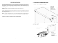
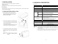
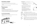
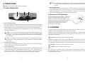
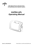
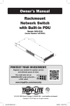
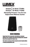
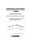
Mason Air AS5000 / AS5000-RR / AS5300 Low air loss/Alternating pressure mattress Instruction Manual Drive Medical Design & Manufacturing 99 Seaview Boulevard Port Washington, NY 11050 Toll Free: 877-224-0946 Local: 516-998-4600 www.drivemedical.com REV3.8.29.14 746002-5150 V1.0 15 PLEASE READ ALL INSTRUCTIONS BEFORE USE. CONTENTS IMPORTANT SAFEGUARDS...................................................... 2 1. INTRODUCTION .................................................................... 3 a/ The ISM (industrial, scientific and medical) bands between 150 kHz and 80 MHz are 6,765 MHz to 6,795 MHz;13,553 MHz to 13,567 MHz; 26,957 MHz to 27,283 MHz; and 40,66 MHz to 40,70 MHz. b/ The compliance levels in the ISM frequency bands between 150 kHz and 80 MHz and in the frequency range 80 MHz to 2.5 GHz are intended to decrease the likelihood that mobile/portable communications equipment could cause interference if it is inadvertently brought into patient areas. For this reason, an additional factor of 10/3 is used in calculating the recommended separation distance for transmitters in these frequency ranges. 2. PRODUCT DESCRIPTION ..................................................... 4 3. INSTALLATION ....................................................................... 5 4. OPERATIONS ......................................................................... 7 c/ Field strengths from fixed transmitters, such as base stations for radio (cellular/cordless) telephones and land mobile radios, amateur radio, AM and FM radio broadcast and TV broadcast cannot be predicted theoretically with accuracy. To assess the electromagnetic environment due to fixed RF transmitters, an electromagnetic site survey should be considered. If the measured field strength in the location in which the device is used exceeds the applicable RF compliance level above, the device should be observed to verify normal operation. If abnormal performance is observed, additional measures may be necessary, such as reorienting or relocating the device. 5. CLEANING.............................................................................. 8 6. MATTRESS STORAGE .......................................................... 9 7. MAINTENANCE ...................................................................... 9 8. TECHNICAL DESCRIPTION ................................................ 10 APPENDIX A: EMC INFORMATION ......................................... 12 d/ Over the frequency range 150 kHz to 80 MHz, field strengths should be less than 3 V/m. Recommended separation distances between portable and mobile RF communications equipment and this device: This device is intended for use in an electromagnetic environment in which radiated RF disturbances are controlled. The customer or the user of this device can help prevent electromagnetic interference by maintaining a minimum distance between portable and mobile RF communications equipment (transmitters) and this device as recommended below, according to the maximum output power of the communications equipment Rated maximum output power Separation distance according to frequency of transmitter m 150 kHz to 80 MHz 80 MHz to 800 MHz 800 MHz to 2,5 GHz d 1.2 P d 1.2 P d 2.3 P 0.01 0.12 0.12 0.23 0.1 0.38 0.38 0.73 1 1.2 1.2 2.3 10 3.8 3.8 7.3 100 12 12 23 of transmitter W For transmitters rated at a maximum output power not listed above, the recommended separation distance d in meters (m) can be estimated using the equation applicable to the frequency of the transmitter, where P is the maximum output power rating of the transmitter in watts (W) according to the transmitter manufacturer. Note 1: At 80 MHz and 800 MHz, the separation distance for the higher frequency range applies. Note 2: These guidelines may not apply in all situations. Electromagnetic propagation is affected by absorption and reflection from structures, objects, and people. 1 14 Guidance and Manufacturer’s Declaration - Electromagnetic Immunity: IMPORTANT SAFEGUARDS This device is intended for use in the electromagnetic environment specified below. The user of this device should make sure it is used in such an environment. Immunity Test IEC60601 test level Compliance Electromagnetic Environment-Guidance Portable and mobile RF communications equipment should be used no closer to any part of this device, including cables, than there commended separation distance calculated from the equation applicable to the frequency of the transmitter. Recommended separation distance d 1.2 P 150kHz to 80MHz d 1.2 P 150kHz to 80MHz d 2.3 P 80 MHz to 2.5G MHz Conducted RF IEC 61000-4-6 Radiated RF IEC 61000-4-3 Where P is the maximum output power rating of the transmitter in watts (W) according to the transmitter manufacturer and d is the recommended separation distance in meters (m).b 3Vrms150 kHz to 80 MHz outside ISM bandsa 3 V/m GHz 3 Vrms Field strengths from fixed RF transmitters, as determined by an electromagnetic site survey c, should be less than the compliance level in each frequency ranged. 80 MHz to 2.5 READ ALL INSTRUCTIONS BEFORE USE DANGER - To reduce the risk of electrical shock: 1. Always unplug this product immediately after using. 2. Do not use while bathing. 3. Do not place or store product where it can fall or be pulled into a tub or sink. 4. Do not place in or drop into water or other liquids. 5. Do not reach for a product that has fallen into water. Unplug immediately. WARNING - To reduce the risk of burns, electrical shock, fire, or injury: 1. This product should never be left unattended when plugged in. 2. Close supervision is necessary when this product is used by, on, or near children or invalids. 3. Use this product only for its intended use as described in this manual. 4. Do not use attachments not recommended by the manufacturer. 5. Never operate this product if it has a damaged cord or plug, if it is not working properly, if it has been dropped or damaged, or exposed to water. Return the product to a service center for examination and repair. 6. Keep the cord away from heated surfaces. 7. Never block the air openings of this product. Never place the product on a soft surface, such as a bed or couch, where the air openings may become blocked. Keep the air openings free of lint, hair, and other similar particles. 8. Never drop or insert any object into any opening or hose on this product. 9. Connect this product to a properly grounded outlet only. See Grounding Instructions. NOTEs, CAUTIONs AND WARNINGs: NOTE CAUTION - Calls attention to useful information, tips, reminders. Calls attention to correct operating or maintenance procedures in order to prevent damage to or destruction of the equipment or other property. WARNING - Calls attention to a potential danger that requires correct operating procedures or practices in order to prevent personal injury. SYMBOL Definitions 3 V/m Interference may occur in the vicinity of equipment marked with the following symbol: Authorized representative in the European community. Manufacturer Complies with standards protecting against electric shock for type BF equipment. Attention, you should read the accompanying information carefully! NOTE 1: At 80 MHz and 800 MHz, the higher frequency range applies. NOTE 2: These guidelines may not apply in all situations. Electromagnetic propagation is affected by absorption and reflection from structures, objects and people. Attention – Observe proper Disposal of Electrical & Electronic Equipment (WEEE): This product should be handed over to an appropriate collection point for the recycling of electrical and electronic equipment. For more detailed information about the recycling of this product, please contact your local city office, household waste disposal service or the retail store where you purchased this product. Consult operating instructions Class II Functional earth. 13 2 APPENDIX A: EMC INFORMATION 1. INTRODUCTION This manual should be used for initial set up of the system and for reference purposes. Guidance and Manufacturer’s Declaration- Electromagnetic Emissions: 1.1 GENERAL INFORMATION This device is intended for use in the electromagnetic environment specified below. The user of this device should make sure it is used in such an environment. This system is a high quality, affordable mattress system, suitable for the treatment and prevention of Emissions Test pressure ulcers. This product has been tested and successfully approved for the following standards: IEC61000-3-2 EN 60601-1 EN 60601-1-2 IEC61000-3-2 IEC 61000-3-3 Medical Equipment-Air Pump with respect to electrical shock, fire and mechanical hazards only in accordance with Immunity Test Electrostatic Discharge (ESD) IEC61000-4-2 Electrical fast transient/ burst Le produit à été testé avec des équipements médicaux et respecte les normes UL 60601-1 & CAN/CSA IEC61000-4-4 1.2 INTENDED USE Surge C22.2 No.601.1. prévenant les choc électrique, le feu et les risques de blessures physiques. IEC61000-4-5 This product is intended: n n The device is suitable for use in all establishments, including domestic establishments and those directly connected to the public low-voltage power supply network. This device is intended for use in the electromagnetic environment specified below. The user of this device should make sure it is used in such an environment. UL60601-1 AND CAN/CSA C22.2 NO.601.1 n Electromagnetic Environment-Guidance Guidance and Manufacturer’s Declaration- Electromagnetic Immunity: FOR US AND CANADA ONLY 53DG Class A Voltage fluctuations / Flicker emissions Complies IEC61000-3-3 EN 55011 Class B E465930 Harmonic emissions Compliance to help and reduce the incidence of pressure ulcers while optimizing patient comfort. for long term home care of patients suffering from pressure ulcers. for pain management as prescribed by a physician. NOTE: This equipment is not suitable for use in the presence of flammable anesthetic mixture with air or with pure oxygen or nitrous oxide. Voltage dips, short interruptions and voltage variations on power supply input lines IEC61000-4-11 NOTE: Lʼéquipement ne peut être utilisé sʼil y a risque de mélange dʼun anesthésique inflammable avec lʼair ou lʼoxygène ou oxyde nitreux. IEC60601 test level Compliance ±6kV contact ±6kV contact ±8kV air ±8kV air ±2kV for power supply line ±2kV for power supply line ±1kV for input/out line ±1kV for input/out line ± 1 kV line(s) to ± 1 kV line(s) to magnetic field Mains power quality should be that of a typical commercial or hospital environment. Mains power quality should be that line(s) of a typical commercial or hospital ± 2 kV line(s) to earth ± 2 kV line(s) to earth environment. <5 % UT (>95 % dip <5 % UT (>95 % dip Mains power quality should be that in UT) for 0,5 cycle in UT)for 0,5 cycle of a typical commercial or hospital 40 % UT (60 % dip in 40 % UT (60 % dip in environment. If the user of this UT)for 5 cycles UT) for 5 cycles device requires continued operation 70 % UT (30 % dip in 70 % UT (30 % dip in during power mains interruptions, it is recommended that the device be UT)for 25 cycles UT) for 25 cycles powered from an uninterruptible <5 % UT (>95 % dip <5 % UT (>95 % dip power supply or a battery. in UT)for 5 sec in UT) for 5 sec 3 A/m 3 A/m IEC61000-4-8 NOTE: UT is the a.c. mains voltage prior to the application of the test level 3 Floors should be wood, concrete or ceramic tile. If floors are covered with synthetic material, the relative humidity should be at least 30%. line(s) Power frequency (50/60Hz) Electromagnetic Environment-Guidance 12 Power frequency magnetic fields should be at levels characteristic of a typical location in a typical commercial or hospital environment. SAVE THESE INSTRUCTIONS GROUNDING INSTRUCTIONS This product should be grounded. In the event of an electrical short circuit grounding reduces the risk of electric shock by providing an escape wire for the electric current. This product is equipped with a cord having a grounding wire with a grounding plug. The plug must be plugged into an outlet that is properly 2. PRODUCT DESCRIPTION 2.1 PUMP AND MATTRESS SYSTEM installed and grounded. 1. CPR Tags DANGER - Improper use of the grounding plug can result in a risk of electric shock. 3. Mattress unit 2. Pump unit 4. Quick Connector If repair or replacement of the cord or plug is necessary, do not connect the grounding wire to either flat blade terminal. The wire with insulation having an outer surface that is green with or without yellow stripes is the grounding wire. NOTE - If the repair or replacement of the cord is necessary, please contact a qualified electrician or serviceman. To reduce the risk of electric shock, do not modify the cord or plug in any way. Check with a qualified electrician or serviceman if the grounding instructions are not completely understood, or if in doubt as to whether the product is properly grounded. 2.2 PUMP UNIT 2 Front View 1. Quick Connector Slot 2. Front Panel 1 3 1 4 2 11 4 Rear View 1. Power Switch 2. Power Cord 3. Mounting Brackets 4. Air Filters 3. INSTALLATION Unpack the box and check the package contents for completeness. Package Content List n Mattress unit x 1 (may not be included if only pump unit is purchased) 8. TECHNICAL DESCRIPTION Specifications: Item Specification n Pump Unit x 1 Power Supply (Note: See n User Manual x 1 rating label on the product) Inspect equipment for damage which may have occurred during shipment. If there is damage, please contact your dealer immediately. Fuse Rating Cycle time Dimension (L x W x H) 3.1 PUMP & MATTRESS INSTALLATION Weight mattress are situated towards the end of the bed T1A, 250V Fixed, 8 min @ 60Hz, 29 x 18.5 x 12.6 (cm) or 11.4" x 7.3" x 5.0" 2.2 Kg or 5 lb Operation:10° C to 40° C (50° F to 104° F) 1. Place the mattress or pad on top of a bed frame. Orient the mattress so that the foot-markers on the AC 100-120V 60 Hz, 0.16 A 14W (For 120V System) Temperature Storage: -15° C to 50° C (5° F to 122° F) Shipping: -15° C to 70° C (5° F to 158° F) Environment Operation: 10% to 90% non-condensing (where pump will be located). Humidity Storage: 10% to 90% non-condensing Shipping:10 % to 90% non-condensing Class II with functional earth(NOTE:5*), Type BF, IPX0 Classification Applied Part: Air Mattress Not suitable for use in the presence of a flammable anesthetic mixture (No AP or APG protection) 2. Place the pump hangers over the bed railing at the foot of the bed. Support the pump from the bottom and turn the hangers outward (or inward) to secure the pump against the railing. If no bed railing is available, place the pump on a flat, sturdy surface or on the floor, beneath the bed. Mattress Specification Model 8” Replacement 200 x 90 x 20.3 (cm) Dimension (L x W x H) or 78.7” x 35.4” x 8” Weight 7.5 kg 16.5 lb Adjustable Weight Settings Pressure Range NOTE: 1. Consult the distributor or EU representative for further technical documents. 2. These specifications are also applicable for other regions operating with the 3. Connect the Quick Connector on the air hose (from air mattress) to the pump unit Quick Connector Slot. When you hear a "click", the connection will be same power supply. 3. The manufacturer reserves the right to modify the specifications without notice. 4. The earthing terminal is served as functional earth, not protective earth. secured. NOTE: Check and ensure the air hoses are not kinked or tucked under the mattress. 5 10 6. MATTRESS STORAGE 4. Plug the power cord into a electrical outlet with the appropriate voltage. NOTE: The pump unit must be suitable for the 1. Lay the mattress on a flat surface, upside-down. local power voltage. 2. Roll-up the mattress starting from the head until you reach the foot of the mattress. NOTE: Sʼassure que la pompe est compatible 3. Use the straps at the end of the mattress and stretch them around the mattress to prevent it from au voltage local ou disponible. unraveling. 6. Note: Do not fold, crease or stack the mattresses. Turn the main power switch (on pump) to the ON position. After you turn on power to the pump, you will have to wait at least 20 minutes for the mattress 7. MAINTENANCE to become fully inflated. 7.1 GENERAL illuminate while the mattress is pressurizing. The low pressure indicator (yellow LED) will When the appropriate pressure is reached, the Low 1. Check the main power cord and plug for abrasions or excess wear. Pressure indicator (yellow LED) will go off and the 2. Check the mattress cover for signs of wear or damage. 3. Disconnect the air tube from the mattress. on the pump. Then check the airflow coming from the two air outlets They should be alternately delivering air when the pump is set at “alternate” mode. 4. Check the air hoses for kinks or breaks. For replacement, please contact your local distributor. 7.2 AIR FILTER REPLACEMENT Normal Pressure indicator (green LED) will illuminate. The bed is now ready for use. NOTE: You can unplug the unit to power-off the device. NOTE: Lʼappareil est également muni dʼune fiehe de connexion à lʼélectricité. CAUTION: The pump supplied with the mattress can only be used for mattresses recommended by the manufacturer. Do not use it for any other purpose. (applied part: air mattress) 1. Open the air filter cap located at the back of pump. 2. The filter is reuseable and can be washed gently with mild detergent and water. Dry the filter before use. AVERTISSEMENT : La pompe ne peut être utilisée quʼavec le matelas designé ou r recommandé par le manufactureier,. Ne pas server dʼysage autre que celui auquel 3. Check and replace air filter regularly if environment is dirty. elle a été conçu NOTE: NOTE: (For models WITHOUT the low-air-loss function) During power outages, you can cover the Quick Connector with the transport cap to maintain air pressure inside the air cells. After installation, make sure any excess cord or tubing is removed from possible foot traffic to avoid accidental tripping. All EQUIPMENT should be positioned to always allow unhindered patient access by physicians and caregivers. Air Filter Air Filter Cap 9 ON 6 NOTE: If the pressure level is consistently low, check for any leakage (tubes or air hoses). If 4. OPERATIONS necessary, replace any damaged tubes or hoses or contact your local qualified dealer for repair. NOTE: Always read the operating instructions before use. 4. Alternate / Static Switch 4.1 PANEL OPERATIONS The ALTERNATE/STATIC switch selects between Alternate Pressure mode and Static Pressure 1 2 mode. 3 With Alternate Pressure mode, alternating air cells are partially deflated and inflated, avoiding prolonged pressure on any single point beneath the patient; this is to prevent pressure ulcers. With Static Pressure mode, all of the air cells are equally inflated. 4.2 Emergency CPR Operations CPR must be performed on a firm surface. Therefore, if an emergency CPR situation occurs with the patient on the mattress, the mattress must be quickly deflated. This is done by quickly pulling on the CPR tag located at the head 4 of the mattress on the patient’s right-side. The quick connector found from the pump unit can also be 1. Pressure Adjustment Knob The pressure adjustment knob controls the air pressure in the mattress. Turning the knob clockwise will increase the pressure; counter-clockwise decreases the pressure. Higher pressures will support heavier patients. The pressure should be adjusted according to individual comfort preferences. When the mattress is finished pressurizing to the desired level of firmness, the Normal Pressure LED indicator will illuminate. NOTE: disconnected to hasten deflation. 5. CLEANING It is important to follow the cleaning procedures before first-time use with any patient; this is to avoid the possibility of transmission of pathogens between patients and caregivers. You can also check if the pressure is suitable for the patient by sliding one hand Wipe down the pump unit with a damp cloth pre-soaked with a mild detergent. Avoid contact with dust beneath the air cells at the level of the patient's buttocks. The air cells will alternately inflate and proximity to dusty areas. Make sure that any cleaning agents you use will not harm or corrode the and deflate. plastic casing on the pump unit. You should feel slight contact with the buttocks when the air cells beneath the buttocks deflate. CAUTION: Do not immerse or soak the pump unit in liquids. NOTE: Every time the mattress is initialized (inflated), it is recommended that you set the pressure knob to "Max" to hasten inflation. You can then adjust the air mattress to the desired Wipe-down the mattress unit with a damp cloth pre-soaked with warm water (do not exceed 65 ℃) firmness later. containing a mild detergent. Avoid dust and proximity to dusty areas. The cover may also be cleaned using sodium hypochlorite diluted in water. 2. Normal Pressure Indicator When the green LED illuminates, the pressure inside of air mattress has reached the desired pressure setting (preset on the Pressure Adjustment Knob). All components should be air dried thoroughly before use. CAUTION: Do not use phenolic based products for cleaning. CAUTION: Do no dry the mattress in direct sunlight. 3. Low Pressure Indicator When the mattress is initializing, the Low Pressure LED will illuminate until the appropriate pressure Otherwise, the Low The carrying bag (if available) should be turned inside-out and completely wiped-down using Pressure LED is a warning, indicating that the pressure in mattress is unusually low. Check to disinfectant solutions. Allow it to air-dry thoroughly and then turn it back and wipe down the outside of ensure all connections are secured and correctly installed as per the installation instructions. the bag with disinfectant solutions. is reached (according to the Pressure Adjustment Knob); this is normal. 7 8