1
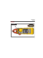
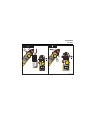
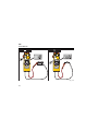
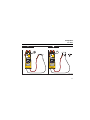
362 Clamp Meter Users Manual PN 3622678 August 2010 © 2010 Fluke Corporation. All rights reserved. Printed in China. Specifications are subject to change without notice. All product names are trademarks of their respective companies. LIMITED WARRANTY AND LIMITATION OF LIABILITY This Fluke product will be free from defects in material and workmanship for two years from the date of purchase. This warranty does not cover fuses, disposable batteries, or damage from accident, neglect, misuse, alteration, contamination, or abnormal conditions of operation or handling. Resellers are not authorized to extend any other warranty on Fluke’s behalf. To obtain service during the warranty period, contact your nearest Fluke authorized service center to obtain return authorization information, then send the product to that Service Center with a description of the problem. THIS WARRANTY IS YOUR ONLY REMEDY. NO OTHER WARRANTIES, SUCH AS FITNESS FOR A PARTICULAR PURPOSE, ARE EXPRESSED OR IMPLIED. FLUKE IS NOT LIABLE FOR ANY SPECIAL, INDIRECT, INCIDENTAL OR CONSEQUENTIAL DAMAGES OR LOSSES, ARISING FROM ANY CAUSE OR THEORY. Since some states or countries do not allow the exclusion or limitation of an implied warranty or of incidental or consequential damages, this limitation of liability may not apply to you. Fluke Corporation P.O. Box 9090 Everett, WA 982069090 U.S.A. 11/99 Fluke Beijing Service Center Room 401 SCITEC Tower Jianguomenwai Dajie Beijing 100004 China P.R. Tel: 400-810-3435 Shanghai Shilu Instrument Co., Ltd. #139, Lane 2638, HongMei Road (S) Shanghai 201108 China P.R. Table of Contents Title Page Introduction................................................................................................................. Contact Fluke ............................................................................................................. Safety Information ...................................................................................................... The Meter ................................................................................................................... Specifications ............................................................................................................. Electrical Specifications.......................................................................................... Mechanical Specifications ...................................................................................... Environmental Specifications ................................................................................. Safety Specifications .............................................................................................. i 1 2 2 7 13 13 14 15 16 362 Users Manual ii Introduction Warning Read "Safety Information" before you use the Meter. The Fluke 362 is a hand-held, battery-operated clamp meter (the Meter) that measures: • ac and dc current and voltage • resistance • continuity The Meter ships with: • TL19B test leads • two AAA batteries (installed) • 362 User Manual 1 362 Users Manual Contact Fluke To contact Fluke, call one of the following telephone numbers: • Technical Support USA: 1-800-44-FLUKE (1-800-443-5853) • Calibration/Repair USA: 1-888-99-FLUKE (1-888-993-5853) • Canada: 1-800-36-FLUKE (1-800-363-5853) • Europe: +31 402-675-200 • Japan: +81-3-3434-0181 • Singapore: +65-738-5655 • China: +86-400-810-3435 • Anywhere in the world: +1-425-446-5500 Or, visit Fluke's website at www.fluke.com. To register your product, visit http://register.fluke.com. To see, print, or download the latest manual supplement, visit http://us.fluke.com/usen/support/manuals. Safety Information A Warning identifies conditions and actions that pose hazard(s) to the user. A Caution identifies conditions and procedures that could cause Meter damage, equipment under test damage, or permanent loss of data. Symbols used on the Meter and in this manual are explained in Table 1. 2 Clamp Meter Safety Information Warning To prevent possible electrical shock or personal injury, follow these guidelines: • Use the Meter only as specified in this manual or the protection provided by the Meter can be compromised. • Examine the case before you use the Meter. Look for cracks or missing plastic. Carefully look at the insulation around the connectors. • Never measure current while the test leads are inserted into the input jacks. • Make sure the battery door is closed and latched before operating the Meter. • Remove the test leads from the Meter before the battery door is opened. • Examine the test leads for damaged insulation or exposed metal. Check test lead continuity. Replace damaged test leads before using the Meter. • Do not use the Meter if it operates incorrectly. Protection can be compromised. When in doubt, have the Meter serviced. • Do not use the Meter around explosive gas, vapor or in damp or wet environments. • Use only type AAA batteries, properly installed in the Meter case, to power the Meter. • When measuring, keep fingers behind the Tactile Barrier. See "The Meter" . 3 362 Users Manual • • • • • • • • • • • 4 To avoid false readings that can lead to electrical shock and injury, replace the batteries as soon as the low battery indicator () appears. When servicing the Meter, use only specified replacement parts. Have the Meter serviced only by qualified service personnel. Be careful around voltages > 30 V ac rms, 42 V ac peak, or 60 V dc. Such voltages pose a shock hazard. Do not apply more than the rated voltage, as marked on the Meter, between the terminals or between any terminal and earth ground. When using the probes, keep fingers behind the finger guards on the probes. Connect the common test lead before connecting the live test lead. When disconnecting test leads, disconnect the live test lead first. Do not work alone so assistance can be rendered in an emergency. Use extreme caution when working around bare conductors or bus bars. Contact with the conductor could result in electric shock. Adhere to local and national safety codes. Individual protective equipment must be used to prevent shock and arc blast injury where hazardous live conductors are exposed. Disconnect circuit power and discharge all high-voltage capacitors before you do diode tests or measure resistance or continuity. Clamp Meter Safety Information • Do not measure ac/dc current in circuits carrying more than 600 V or 200 A with the Meter Jaw. Never operate the Meter with the back cover removed or the case open. • Caution To avoid possible damage to the Meter or to equipment under test: • Use the proper jacks, function, and range for the measurement application. • Clean the case and accessories with a damp cloth and mild detergent only. Do not use abrasives or solvents. Table 1. Symbols Symbol Meaning AC (Alternating Current) Symbol Meaning Earth ground DC (Direct Current) Do not dispose of this product as unsorted municipal waste. Go to Fluke’s website for recycling information. Hazardous voltage Conforms to European Union directives. 5 362 Users Manual Symbol Meaning Symbol Meaning Risk of Danger. Important information. See Manual. Double insulated Battery. Low battery when shown on display. Application around and removal from HAZARDOUS LIVE conductors is permitted. IEC Measurement Category III CAT III equipment has protection against transients in equipment in fixed-equipment installations, such as distribution panels, feeders and short branch circuits, and lighting systems in large buildings. Note The Measurement Category (CAT) and voltage rating of any combination of test probe, test probe accessory, current clamp accessory, and the Meter is the LOWEST rating of any individual component. CAT III 6 Clamp Meter The Meter The Meter Clamp Meter 1 fig01.eps 7 362 Users Manual Auto Power Off Display Hold V AC VA AC DC V AC 15 ON VA AC DC fig02_3.eps 8 Clamp Meter The Meter AC A A DC A A AC A DC Fig04_05.eps 9 362 Users Manual fig06_07.eps 10 Clamp Meter The Meter e R 70 Fig08_09.eps 11 362 Users Manual 2 1 Fig10.eps 12 Clamp Meter Specifications Specifications Electrical Specifications AC Current Range .....................................................200.0 A Resolution ...............................................0.1 A Accuracy .................................................2 % ±5 digit (45-65 Hz) 2.5 % ±5 digits (65-400 Hz) DC Current Range .....................................................200.0 A Resolution ...............................................0.1 A Accuracy .................................................2 % ±5 digit AC Voltage Range .....................................................600.0 V Resolution ...............................................0.1 V Accuracy .................................................1.5 % ±5 digits (45-400 Hz) 13 362 Users Manual DC Voltage Range ..................................................... 600.0 V Resolution ............................................... 0.1 V Accuracy ................................................. 1 % ±5 digits Resistance Range ..................................................... 300 Ω/ 3000 Ω Resolution ............................................... 0.1 Ω/1 Ω Accuracy ................................................. 1 % ±5 digits Continuity Beeper on Threshold .............................. ≤ 70 Ω Mechanical Specifications Size (L x W x H) ..................................... 205 x 60 x 22 mm Weight..................................................... 196 g Jaw Opening ........................................... 18 mm 14 Clamp Meter Specifications Environmental Specifications Operating Temperature...........................0 °C to +40 °C Storage Temperature..............................-30 °C to +60 °C, 100 hours under -40 °C Operating Humidity .................................Non condensing (< 10 °C) ≤ 90 % RH (at 10 °C to 30 °C) ≤ 75 % RH (at 30 °C to 40 °C) ≤ 45 % RH (at 40 °C to 50 °C) (Without Condensation) Operating Altitude ...................................2000 meters Storage Altitude ......................................12,000 meters IP Rating .................................................IP 30 per IEC60529:2001; Case Vibration Requirements MIL-T-28800E, Class 2 MIL-T-28800E, Class 3 15 362 Users Manual EMI, EMC EN61326-1:2006 Temperature Coefficients........................ Add 0.1 x specified accuracy for each degree C above 28 °C or below 18 °C Safety Specifications Safety Compliance.................................. ANSI/ISA S82.02.01:2004 CAN/CSA-C22.2 No. 61010-1-04 IEC/EN 61010-1:2001 CAT III 600V Pollution Degree 2 Batteries.................................................. 2 AAA 16