1
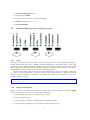
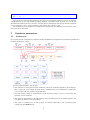
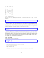
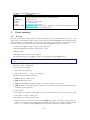
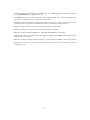
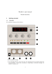
Shruti-1 user manual
Mutable Instruments
There are two things you need to learn to use the Shruti-1:
• How to use the interface and navigate through the different pages.
• What are the different synthesis parameters and how they affect sound.
But before that, you’ll also need to know how to plug-in cables!
• Connect your synth/computer’s MIDI out to the Shruti-1’s MIDI in.
• Connect the Shruti-1’s Audio out to a mixer or sound card.
• You can use any 7.5V-9V power supply with a 2.1mm jack to power the Shruti-1. Make sure that
it has a center pin positive / outer collar negative pin connector. With most universal power
supplies, you can select the polarity – there’s a little diagram on the connector showing you its
polarity. It should look like this: - (o +
You can now power the Shruti-1. It should display the startup screen:
1
Controls and navigation
1.1
Controls
Besides the on-off switch, the Shruti-1 provides the following controls:
• The output volume and input gain knobs
• 5 group selection buttons
1
• 2 increment/decrement buttons
• 4 general purpose knobs
The current status of the synth is visualized through:
• 12 LEDs, grouped by 3, 1, 4, 3, 1
• A 2x16 LCD display
1.2
Understanding the page and group system
1.2.1
Pages
The Shruti-1 has 4 knobs, but this doesn’t mean that there are only 4 sound synthesis parameters to
tweak! These knobs will control a different parameter depending on the current "page". Each page
allows you to edit 4 different parameters related to one aspect of sound production. For example, on the
"Filter" page, you can edit the filter cutoff, filter resonance, envelope to filter modulation, and LFO to
filter modulation. There are 12 pages, as shown on the diagram above.
It’s easy to know which page you are in: First, each LED indicator in the row of 12 LEDs corresponds
to a page. If the first LED is lit - you are at the first page, editing oscillator 1. Moreover, the LCD
display is constantly showing you which knob does what in the current page. For example, if you are at
the filter page, you can see:
cut res env lfo
110
0 10
0
1.2.2
Groups and navigation
Alright, so how do we move from one page to another? By repeatedly pressing one of the 5 group
buttons. Each button allows you to cycle through related pages:
1. Cycles through the oscillator 1, oscillator 2, mixer pages
2. Jumps to the filter page
3. Cycles through the envelope 1, envelope 2, lfos, modulations pages
4. Cycles through the arpeggiator, step sequencer, keyboard/tuning pages
2
5. Jumps to the patch load/save page
It’s easy to remember how the cycles are organized - just look at the grouping of the LEDs - they
show you which pages are bundled with each other ; and they sit just on top of the button that cycles
through them. Let’s take a simple example. When you switch on the Shruti-1, the current page is the
Filter page. The 4th LED is lit and the synth is showing:
cut res env lfo
110
0 10
0
Press the 4th button, this jumps to the arpeggiator page:
bpm oct pat swg
120
0 |1
0
9th LED is lit. Press this button again. This brings the next page in the group, the step sequencer:
step sequencer
0000ffffcccc4444
10th LED is lit. Press again. This brings the keyboard/tuning page:
oct rag prt chn
0 equ
0
1
11th LED is lit. Press again. The 9th LED is lit and we’re back to the arpeggiator:
bpm oct pat swg
120
0 |1
0
Now let’s move to the oscillators. Press the first button. The 1st LED lights up and the display
shows:
sha prm rng op
saw
0
0 1+2
1.2.3
Editing parameters
When a page is active, the Shruti-1 shows you four parameters that can be edited. You can simply adjust
one of those parameters by turning the corresponding knob. For example, when the filter page is active:
cut res env lfo
110
0 10
0
You can turn the first knob to control the filter cutoff. While you turn the knob, the Shruti-1 "deep
dives" on this parameter and really tells you what it’s all about (no pesky abbreviation...):
filter
cutoff
89
When you are done, after a short time lapse, the display gets back to showing the 4 parameters:
3
cut res env lfo
89
0 10
0
Pots are super nice for tweaking filters, but not that great for selecting items in a long list or adjusting
a BPM precisely. If you find yourself struggling adjusting a parameter with the knob, you can use the
decrement/increment buttons on the right. The first button will decrease the value of the last parameter
you’ve touched by 1 unit ; the second button will increase this value by 1 unit.
The modulations, step sequencer and patch/load save pages are a bit different from the others, we’ll
learn more about this later!
2
Synthesis parameters
2.1
Architecture
Let’s start by the big "architecture" schematic showing the different sound generation/modulation/modification
modules the Shruti-1 contain:
Sounds complicated huh? Step by step:
• The oscillators 1 and 2 generate basic waveforms, which are combined together by the modulator.
Most of the time, you’ll simply mix them with a variable balance, but sometimes you might want
to do weirder stuff (for example, ring-modulation)
• The sub-oscillator (which is synchronized in pitch with the oscillator 1, but 1 octave lower) also
generates a basic waveform
• The output of the modulator, the sub-oscillator and some additional noise are mixed together. You
can adjust the balance of each ingredient
• The result is converted into an analog signal, and mixed "electrically" with an external signal
coming from the Audio in jack
4
• The result is then sent to an analog VCF and VCA, to produce the final audio signal
Each of these modules has parameters (represented by the blue arrows) which can be controlled by
any of the modulation sources listed below. Some connections are "hardwired" (or rather "softwired" in
the firmware):
• The oscillators’ pitch always tracks the note
• Lfo 2 and Envelope 1 are always connected to the filter, but you can adjust the modulation amount
and by default it is set to 0
Additionally, the Shruti-1 has "patchcords" already in place for the following routing:
Source
Lfo 1
Lfo 1
Lfo 2
Lfo 2
Lfo 2
Note
Envelope 2
Velocity
Bender
LFO
CV1
CV2
CV3
random
Destination
Oscillator 1 coarse pitch
Oscillator 2 coarse pitch
Oscillator 1 PWM
Oscillator 2 PWM
Oscillators balance
Filter cutoff
VCA gain
VCA gain
Oscillator 1+2 fine pitch
Oscillator 1+2 fine pitch (vibrato)
Oscillator 1 PWM
Oscillator 2 PWM
Filter cutoff
Filter cutoff
Amount
0
0
0
0
0
(tracks)
100%
25%
2 semitones
2 semitones
0
0
0
0
2.2
Synthesis parameters, page by page
2.2.1
Oscillator 1
sha prm rng op
saw
0
0 1+2
• sha (shape): Oscillator 1 waveform shape
• prm (parameter): Oscillator 1 parameter (see below)
• rng (range): Oscillator 1 pitch transposition, from -12 semitones to 12 semitones
• op (operator): Modulator operation (see below)
The Oscillator 1 is the richest. The following is a list of all the available waveforms, with some
applications and a description of what adjusting the parameter setting does:
2.2.2
none: Silence
Sometimes you just want the Shruti-1 to shut up to process an external signal. This oscillator does not
output any sound.
2.2.3
blit: Impulse train
5
This waveform is a high-pass filtered square wave (or the other way round... the square wave is
actually built by low-pass filtering this thing). The parameter controls the spacing between the pairs of
up/down pulses. This oscillator is good for thin sounds (casio harpsichord), and for simulating sounds
filtered by a high-pass / band-pass filter.
2.2.4
saw: Sawtooth
This waveform is perfect for basses and brass sounds. The parameter controls the waveshapping when you increase its value, it shifts up an increasingly large section of the waveform.
2.2.5
square: Square wave
The parameter controls the pulse-width. This waveform is perfect for simulating a clarinet, for basses,
"hollow" sounds or Depeche Mode-like leads - the aliasing is under control!
2.2.6
triang: Triangle
A pure waveform, which can create a good "NES bass". The waveshapping parameter controls which
fraction of the waveform is zero’ed out.
2.2.7
cz: Sawtooth with sweepable resonance
This waveform is a simple imitation of the acid sounds produced by the Casio CZ-101. It uses a
clever phase distortion/sync trick to simulate a sawtooth filtered by a low-pass filter with high resonance.
The frequency of the resonance is controlled by the parameter. Using this oscillator, you can simulate
doubly-filtered sounds, or even formants.
2.2.8
fm: Minimal 2-operators FM
The parameter controls the modulation strength. This oscillator provides the base material for metallic
sounds, bells, metallophones, or the next 386 DX hit.
6
2.2.9
8bits: 8-bits
A large range of harsh, 8-bits sounding waveforms born from a dirty programming trick. The parameter
scans through the different waveforms, which are perfect for trashy and chippy sounds.
2.2.10
pwm: Shameless square wave without anti-aliasing
The parameter controls the pulse-width. Contrary to square, this waveform stinks aliasing. But you
know what? Below C2, we don’t care and this sounds so fat. But please, don’t use for leads/sequences
with notes above C3, unless you want that typical "my first Arduino synth" sound.
2.2.11
noise: Filtered noise generator
The parameter controls the frequency of a simple 1-pole low-pass/high-pass filter in which is sent white
noise. From 0 to 63, you progressively add high-frequency content. From 63 to 127, you progressively
remove low-frequency content. Perfect as a raw material for percussions or sound effects.
2.2.12
vowel: Low-tech formant synthesis
By changing the parameter, you’ll sweep between different vocal-like sounds (14 vowels and 2 consonants). Now. Spell. Daftpunk.
2.2.13
table: 32-waves wavetable
A wavetable with organ/digital piano single cycle waveforms. The parameter allows you to scan and
interpolate through the different waveforms in the table. This oscillator is a good start for organs, digital
piano imitations, drones...
2.2.14
sweep: blit/saw/square/triangle scan
This is a "meta-oscillator". Depending on the value of its parameter it will behave like a blit, a saw, a
square or triangle oscillator. Perfect for evolutive wave sequences or SID-like madness.
Important Quirks ahoy!
Now I have to confess three quirky things about the oscillators I am very ashamed of:
7
1. When you use the fm oscillator, the range parameter doesn’t affect the carrier (that is to say,
the pitch of the note you’re hearing), it is affecting the modulator, in a non linear way. So when
you use fm and adjust the range parameter, it won’t "detune" oscillator 1, it will just go through
different, categories of FM timbres.
2. The vowel oscillator, largely based on Peter Knight’s Cantarino, is CPU intensive. When you
use this oscillator, the sub-oscillator and noise generator are switched off to handle the extra
computational load.
3. There’s a very noticeable difference between the Square oscillator with pulse width = 0 and pulse
width > 0. To give you the best sound, the pulse width = 0 case is read straight from a wavetable
at full sample rate, while the non zero pulse width case is an integrated blit (which doesn’t sound
as good) at half the sample rate. So if you want to do PWM, make sure it does not go to 0 or
you’ll hear the discontinuity. Now you know why early digital/analog hybrid synths (JX8P, ESQ-1)
did not have PWM!
As for the "operator" parameter, the different modulation modes are:
Operator
Description
1+2
Mixing
1>2
Mixing and synchronization:
oscillator 2’s phase is reset
whenever oscillator 1’s phase
is reset. You won’t hear the
detuning, but instead a timbral modulation
Ring modulation - oscillators’
signals are scaled and multiplied
XOR modulation. The bits
of oscillator’s 1 and 2 digital
values are exclusive-or’ed, and
the result is shifted
1*2
1|2
What does the oscillator balance parameter do?
Adjusts the oscillator 1/2 balance
Adjusts the oscillator 1/2 balance
Applications
Everything
Psy-trance, Devo
Nothing
Bells, Os Mutantes
Shifts the output, with overflow
This utterly fucks up the signal, and is relevant to any situation where a fucked-up signal is required
Important XOR modulation might make the Shruti-1 sounds like it’s reading the Track-1 of a CD/CDROM or a text file mistakenly renamed "sample.wav". Use moderately
2.2.15
Oscillator 2
sha prm rng tun
saw
0
0
0
• sha (shape): Oscillator 2 waveform shape. The choice here is restricted to the classics: blit /
saw / pulse / triangle
• prm (parameter): Oscillator 2 parameter
• rng (range): Oscillator 2 pitch transposition, from -24 semitones to 24 semitones
• tun (detune): Fine detuning of Oscillator 2
8
2.2.16
Mixer
mix sub noi sha
32
0
0 tri
•
mix (osc bal): Oscillator 1/2 balance. Might do something different than balance when an
operator different from "1+2" is selected (see the Oscillator 1 section)
• sub (sub osc.): Sub oscillator level
• noi (noise): Noise level
• sha (shape): Sub oscillator shape (triangle or square)
Important Quirks ahoy!
1. The noise is a bit colored in the low-end (pink instead of white), and is here to make harmonic
sounds sound dirtier. If you rather want harsh, bright white noise to create snares or hi-hats, you’d
rather use the noise from oscillator 1!
2. The sub-oscillator is not that razor-sharp compared to the main oscillators. This doesn’t matter
for the triangle wave, but if you really want a low, fat, square underneath your main saw or square,
you’d rather use the pwm waveform on oscillator 1, set to -12 semitones, and your main oscillator
on oscillator 2.
2.2.17
Filter
cut res env lfo
66
0 16 37
• cut (cutoff): Filter cutoff frequency
• res (resonance): Filter resonance
• env (env1->vcf): Modulation amount from envelope 1 to VCF. If you want to set a negative
modulation amount, no problem, you can patch env1 to the VCF in the modulations section and
ignore this parameter
• lfo (lfo2->vcf): Modulation amount from LFO 2 to VCF. Again, if you want to set a negative
modulation amount, you can patch the LFO 2 to the VCF in the modulations section and ignore
this parameter
2.2.18
Envelope 1 / 2
atk dec sus rel
0 44 20 60
• atk (attack): Envelope attack time
• dec (decay): Envelope decay time
• sus (sustain): Envelope sustain level
• rel (release): Envelope release time
9
2.2.19
LFOs
wv1 rt1 wv2 rt2
tri 80 tri x16
• wv1 (lfo1 wave): LFO1 waveform: triangle, square, sample&hold, ramp (sawtooth)
• rt1 (lfo1 rate): LFO1 rate
• wv2 (lfo2 wave): LFO2 waveform: triangle, square, sample&hold, ramp (sawtooth)
• rt2 (lfo2 rate): LFO2 rate
Wait, what’s this x-something when I set the LFO-rate to a low value? This is the Clock>LFO
synchronization! x16 simply means "the LFO will do one full cycle over a duration of 16 sequencer
steps (4 beats)". For example, if you set the LFO to a ramp, with a rate of x4, and map it to the cutoff,
the cutoff will raise over the duration of a beat and return to a low value at the beginning of each beat.
With a x2 or x1 rate, square LFO mapped to the VCA, you can get old-school trancey gater effects.
With a x2 rate, sample&hold LFO mapped to the cutoff and the basic arpeggiator pattern, with high
resonance, you get a random bleeping at every note.
2.2.20
Modulation matrix
Remember this big schematics with all those parameters and modulation sources? This page is where
we connect the dots!
The first thing about this page is that it works a bit differently from the others... The first knob
allows you to select a patchcord, while the knobs 2-4 allow you to edit it. Let’s see how it look:
mod src dst amt
1 lf1 ~1
0
This page means: "The patchcord #1 connects the LFO1 to the oscillator 1 pitch, and the corresponding modulation amount is set to 0". If you turn the first knob, you’ll scroll through the different
connections in place, for example:
mod src dst amt
6 not cut 58
"The patchcord #6 connects the note number to the filter cutoff, and the corresponding modulation
amount is 58" (58 is what gave me the best pitch/cutoff coupling - it might depend a bit on your CEM
though)
Once you have selected a patchcord (with the first knob) you can select its source/destination/amount
with the 3 other knobs. While you’re editing the amount, the Shruti-1 is super-nice and shows you exactly
what you are editing:
mod not>cut
amount
56
The modulation sources are, in modern lovers precise order:
1. lfo1: LFO1 output (centered)
2. lfo2: LFO2 output (centered)
10
3. stpseq: Step sequencer output
4. arp: Arpeggiator gater (this is a binary, all or nothing, control signal)
5. mwheel: Modulation wheel value read from the MIDI in
6. bender: Pitch-bend controller value read from the MIDI in (centered)
7. offset: A boring constant value. Why would you want that? It’s more like a placeholder for future
modulation sources!
8. cv1: Control voltage read from the HACK_ME connector
9. cv2: Control voltage read from the HACK_ME connector
10. cv3: Control voltage read from the HACK_ME connector
11. random: Another random/noise generator! Mapped to the VCA, makes for some super snares!
12. env1: Envelope 1
13. velo: Velocity of the last played note
14. note: Pitch of the currently played note (centered)
15. gate: Keyboard gater (yet another binary control signal)
The modulation destinations are, in modern lovers precise order:
1. cutoff: Filter cutoff
2. vca: VCA gain
3. pwm1: Oscillator 1 parameter (can be pulse width, but also waveshapping, phoneme, depending
on the oscillator type)
4. pwm2: Oscillator 2 parameter (can be pulse width, but also waveshapping, phoneme, depending
on the oscillator type)
5. osc1: Coarse oscillator 1 pitch, in a -16 / 16 semitones range. Also affects the sub-oscillator’s
pitch
6. osc2: Coarse oscillator 2 pitch, in a -16 / 16 semitones range.
7. osc1+osc2: Fine oscillator 1+2 pitch, in a -4 / 4 semitones range. Also affects the sub-oscillator’s
pitch
8. mix: Oscillator 1/2 balance (or whatever the modulator does with the balance parameter)
9. noise: Noise volume
10. subosc: Sub-oscillator volume
11. reso: Filter resonance
Wait, what does it mean for a modulation source to be centered ? Let’s take an example. We have a
triangle LFO mapped to the filter cutoff, with a modulation amount of 30. If the cutoff is set to 80, the
actual value of the cutoff will oscillate between 50 (80-30) and 110 (80+30). On the other hand, if we
have an envelope mapped to the cutoff with a modulation amount of 20, the cutoff will go from 80 to
120 (80 + 2 * 20), then down to 80 after the release. This is something to remember if you want to do
PWM, for example. If you set the PWM modulation amount to 40, you also have to set the oscillator
pulse width value to 40, so it oscillates between 40-40 = 0 and 40+40=80. Otherwise, it will spend half
of the time stuck at 0. But this makes things nicer for vibrato, tremolo, wah-wah/growl!
11
Important Quirks ahoy!
1. When you are in the modulation matrix page, the page indicator LED will blink/dim to visualize
the value of the selected modulation source
2. The settings for patch cords 11-14 are not saved to memory when you save a sound. Use them for
performances, experimentation, etc
3. You’re going to hate me for this one: The modulation amount of patch cord 10 is adjusted by the
modwheel. Huh? Let’s say you set patch cord 10 to go from LFO 1 to the oscillators fine pitch
with an amount of 16:
mod src dst amt
10 lf1
~ 16
This modulation will be triggered with an amount proportional to the modwheel position - by default
it won’t be active until you start moving the modulation wheel, and to get it at full strength, you’ll have
to push the modulation wheel to the max.
2.2.21
Arpeggiator
bpm oct pat swg
120
2 |1 28
• bpm: Arpeggiator/step sequencer/lfos clock tempo in BPM. extern will sync to the clock ticks
received from the MIDI input
• oct: Octave range of the arpeggiator. When set to 0, the arpeggiator is off
• pat: Pattern. The patterns are numbered from 1 to 15 and are available in 4 flavors: up (arrow
pointing up), down (arrow pointing down), up/down (wave) and random (question mark)
• swg: Swing ratio of the internal clock
The arpeggiator patterns are the following:
1:
2:
3:
4:
o o
ooo
o o
o o
o o o o
ooo ooo
ooooo o
oo oo o
o o
ooo
oooo
oo o
12
5:
6:
7:
8:
9:
10:
11:
12:
13:
14:
15:
oooo oo oooo oo
o o
o o
o o o o o o
o o o o o o
o o o o o o
oo oo oooo oo oo
ooooo oo oo ooo
o
o
o o o o
o oo
o o o oo
o
oooooo oo
o
o
o oo
2.2.22
Step sequencer
This page works a bit differently from the others... It shows the value of the 16 steps of the step
sequencer:
step sequencer
0000ffffcccc4444
And has a blinking cursor. Use the second knob to move the cursor (remember the days gaming
consoles controllers were pots?), the third knob or the inc/dec buttons to adjust the value associated
with each step. The values are displayed in hexadecimal (a=10, b=11, c=12, d=13, e=14, f=15). The
fourth knob is used to adjust the cycle length. Note that the cycle length setting is also applied to the
arpeggiator. When the cycle length is shorter, the other steps are left blank:
step sequencer
02468ace80
When the step-sequencer or arpeggiator are playing, the 12th LED in the row blinks every 4th step
(Step 0: bright, steps 4, 8, 12: dim). You’ll notice that even after releasing a key, the LED continues
blinking - the arpeggiator and the sequencer continue counting steps so that the sequence/pattern won’t
be interrupted if you start playing again. After 4 beats without any new key press, they stop and the
next time you press a key they will restart playing the pattern from step 0. This delay makes it easier to
play complex chords sequences with the arpeggiator on.
2.2.23
Keyboard
To end this long section, a no-quirks page:
oct rag prt chn
0 equ
0
1
• oct: Transpose every note by -2, -1, 0, 1 or 2 octaves
• rag: Scale/keyboard mapping
• prt: Portamento time
• chn: Midi channel the Shruti-1 is tuned to. Set to 0 to receive from every channel
13
The different scales/keyboard mappings are:
Name
equal
just
pythagorean
1/4 eb
1/4 e
1/4 ea
kanaka ... rasika
3
Description
Equal temperament
Just intonation (frequency ratios are rational numbers)
Pythagorean scale
E and B are 1/4 tone lower
E is 1/4 tone lower
E and A are 1/4 tone lower
Melkartam ragas from Kanakangi to Rasikapriya. The keyboard mappings used are the
same as those given on the wikipedia pages
Patch memory
3.1
Saving
Now that you’ve read all this and have created the killer patch, you probably want to save it. The
Shruti-1 has a small memory of 16 patches. The patches are saved in EEPROM so they will persist even
when the Shruti-1 is powered down. First thing to know about patch memory: some settings are not
saved! From the pages we’ve seen so far, here are the settings not saved with your patch:
• Sequencer/arpeggiator tempo, swing, pattern, #octaves
• Keyboard settings (portamento, transposition, scale)
• MIDI channel
• Modulation patch cords 11, 12, 13 and 14
The load/save page is a bit different. Jump to it by pressing the 5th group button:
patch bank
1 new
----
From left to right, are displayed:
1. The memory slot number
2. The patch name (8 letters)
3. The current action ( –– means "do nothing")
The knobs have the following functions:
• knob 1: Selects a memory slot
• knob 2: Moves the cursor
• knob 3 / inc / dec: Changes the letter at the current position of the cursor
• knob 4: Selects an operation (load on the left or save on the right). in the middle position, this
cancels the current operation
To save a patch:
• Turn knob 4 to the right to select save. The cursor starts blinking to indicate we’re in save mode
• Turn knob 1 to select a memory slot
• Use knobs 2/3 to edit the patch name
• When the name is correctly set, press the 5th group button again. The Shruti-1 will go busy for
a short while and the patch will be saved. Otherwise, any other action, including turning the 4th
knob to –– or pressing another group button would have not written anything in memory
14
3.2
Loading
• Turn knob 4 to the left to select load
• Turn knob 1 to browse the patch library
• If you want to get back to the patch you were editing, turn the knob 4 back to ––
4
Advanced topics
4.1
Long presses
Some special functions can be triggered by pressing group buttons for more than 1s.
4.1.1
Test note
Press the keyboard/performance group button (the 4th one) for more than 1s and release. A C3 note
will be played. Press, hold and release again to stop. This is very useful when working on the firmware you can keep your hands on your computer keyboard...
4.1.2
Performance page and Blinkenlights
The performance page allows you to gather 4 parameters from different pages and put them altogether
in a single page - so you don’t have to jump continuously from one page to another while performing.
To assign a parameter to one of the knobs in the performance page:
1. Adjust the value of the parameter you want to "import" to the performance page
2. Hold the filter group button (2nd one) and release
3. Turn the knob to which you want to assign the parameter you’ve just edited
4. Repeat
At step 2, the screen should display this:
touch a knob to
assign parameter
Then, to jump to the performance page, press the oscillator group button and release. The 4
parameters you have assigned to the knobs are all there. Wait, there’s more! In the performance
page, the brightness of the first 11 LEDs of the row will reflect the value of each of the 11 modulation
destinations (filter cutoff, VCA gain, oscillators PWM...). When your modulation matrix is charged with
LFOs, the step sequencer or the arpeggiator gate, it makes for really nice christmas decorations!
4.1.3
Firmware update by MIDI
Good news: you don’t need to open the Shruti-1 to update its firmware! Hold the patch bank button
when powering on the Shruti-1 and you’ll enter in a special firmware update mode. The LEDs #9 (_i’m
waiting for data_) and #11 (_from the MIDI port_) will be lit and the Shruti-1 will wait for some
special SysEx commands contained in the firmware update MIDI file. At this moment, you can play from
your favorite sequencer the MIDI file containing the firmware update. This takes about a minute, during
which nothing should interrupt the operation (be it a disconnected cable or a power failure). The first
8 LEDs monitor the transfer, like a progress bar. The 9th LED blinks at each chunk received ; the 10th
LED should be off. In case things go wrong and the Shruti-1 does not boot after the update, don’t panic!
You can power the Shruti-1 off and start again the entire operation.
You can also initiate a firmware update by holding the patch bank button for a couple of seconds
(two mississippis). The screen will display:
15
ready
for os update
And welcome to firmware-update land!
Important An easy way of screwing up the firmware upload process is to play the update MIDI file
from another position than its start, or to increase the tempo thinking that this will speed up the process.
Don’t do that.
4.2
Easter egg
There’s an easter egg and you’re gonna find it.
4.3
MIDI
4.3.1
Patch reception and transmission
Whenever you save a patch, it is also transmitted to the MIDI out, as a SysEx block. You can record this
into your favorite sequencer and replay it back. The Shruti-1 will receive the data and this will become
the current patch.
Warning When receiving a patch by SysEx, the received patch is not written to patch memory, it is
only temporarily loaded in memory so you can edit it, and if you’re happy with it, save it yourself. There’s
no bulk patch load/save from eeprom by SysEx
Warning Tip: since you don’t risk overwriting stuff in memory when using SysEx patch transfer, use
it and abuse it! For example, embed at the beginning of each of your tracks a dump of the patch, so
your Shruti-1 will always recall the correct patch settings when you play it. We call it, ahem, Sysexual
reproduction.
4.3.2
MIDI implementation
The Shruti-1 understands the following MIDI messages:
• note on/off
• clock tick
• play/stop (activates the step sequencer and arpeggiator)
• pitch bend and modulation wheel
• a bunch of specific control changes (portamento time, release, attack, brightness/harmonic intensity
which are mapped to cutoff and resonance)
• SysEx patch transfer
• some NRPNs. Note that the NRPN implementation is rough and doesn’t check the validity of the
data, so you might crash your Shruti-1 or trigger "interesting" side-effects or secret waveforms by
sending out of range values.
NRPN MSB is always equal to 0. You don’t even need to transmit it. Data Entry MSB is almost
always 0 - except for parameters which can take negative values or values above 127. Negative number
are represented in 2’s complement.
For example, the MIDI messages to send to set the Oscillator 1 range to -12:
16
176
176
176
176
99 0 (NRPN MSB set to 0)
98 4 (NRPN LSB set to 4, from the table below Oscillator 1 range)
6 1 (Data Entry MSB set to 1 -- value above 127 or negative)
38 116 (Data Entry LSB set to 116, because 116 - 128 = -12)
NRPN LSB
0
1
2
3
4
5
6
7
8
9
10
11
12
13
14
15
16
17
18
19
20
21
22
23
24
25
26
27
28 + 3 * (n - 1)
29 + 3 * (n - 1)
30 + 3 * (n - 1)
70
71
72
73
74-81
82
83
84
85
86-93
94
4.4
Parameter
Oscillator 1 shape
Oscillator 2 shape
Oscillator 1 parameter
Oscillator 2 parameter
Oscillator 1 range
Oscillator 2 range
Modulator mode
Oscillator 2 detuning
Oscillator balance
Sub oscillator volume
Noise volume
Sub oscillator shape
Filter cutoff
Filter resonance
Envelope->cutoff modulation amount
Lfo->cutoff modulation amount
Envelope1 attack
Envelope2 attack
Envelope1 decay
Envelope2 decay
Envelope1 sustain
Envelope2 sustain
Envelope1 release
Envelope2 release
Lfo1 Wave
Lfo2 Wave
Lfo1 Rate
Lfo2 Rate
Modulation source
Modulation destination
Modulation amount
Tempo
Arpeggiator octaves
Arpeggiator pattern
Clock swing
Step sequence
Octave shift
Scale/raga
Portamento time
MIDI Channel
Patch name
Cycle length
Range
0-12
1-4
0-127
0-127
-12-12
-24-24
0-3
0-127
0-63
0-63
0-63
3-4
0-127
0-63
0-63
0-63
0-127
0-127
0-127
0-127
0-127
0-127
0-127
0-127
0-3
0-3
0-127
0-127
0-15
0-10
0-63
40-240
0-4
0-59
0-127
0-255
-2-2
0-77
0-127
0-16
32-127
1-16
Bootloader-land
Warning You really want to know?
The bootloader is a short piece of code that gets executed every time you power-up the Shruti-1
or initiate an OS update. It is different from the firmware – no matter which firmware you put on the
Shruti-1 by MIDI update, the bootloader will always be there to allow you to revert your synth back to
its original state.
The bootloader does the following things:
17
• Check if the Shruti-1 is powered-up the normal way, or if a MIDI update was initiated (by a press
on the patch bank button during power up).
• If a MIDI update was initiated, wait for incoming SysEx firmware data. Write the firmware, and
then reset for normal operation at the end of the transfer.
• Otherwise check for data from a Serial programmer. If no data is coming, start the Shruti-1 for
normal operation. Otherwise, read/write chip data as instructed by the programmer.
The status of the bootloader can be monitored by the 12 front panel LEDs:
• LEDs 1-8 behave as a progress indicator when uploading the firmware.
• LED 9 is lit when waiting for MIDI data, and blinks when MIDI data is received.
• LED 10 is lit when a communication with a serial programmer (STK500) has been initiated, and
blinks as data is received.
• LED 11 is lit when a firmware update operation is in progress (be it by MIDI or serial programmer).
• LED 12 is lit for a short amount of time when the bootloader starts. It is then lit in case of
transmission error.
18