1
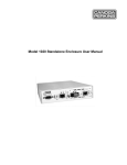
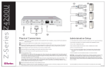
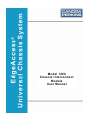
Model 1200
Chassis Interconnect
Module
User Manual
EdgeAccess Universal Chassis System
NOTICE!
This device contains static sensitive components. It should be handled only with proper
Electrostatic Discharge (ESD) grounding procedures.
NOTE!
Cet équipement contient des composants sensibles aux décharges électro-statiques. Il doit
absolument être manipulé en respectant les règles de mise à la terre afin de prévenir de telles
décharges.
NOTICE
Canoga Perkins has prepared this users manual for use by customers and Canoga Perkins
personnel as a guide for the proper installation, operation and/or maintenance of Canoga Perkins
equipment. The drawings, specifications and information contained in this document are the
property of Canoga Perkins and any unauthorized use or disclosure of such drawings,
specifications and information is prohibited.
Canoga Perkins reserves the right to change or update the contents of this manual and to change
the specifications of its products at any time without prior notification. Every effort has been
made to keep the information in this document current and accurate as of the date of publication
or revision. However, no guarantee is given or implied that the document is error free or that it is
accurate with regard to any specification.
CANOGA PERKINS CORPORATION
20600 Prairie Street
Chatsworth, California 91311-6008
Business Phone: (818) 718-6300
(Monday through Friday 7 a.m. - 5 p.m. Pacific Time)
FAX: (818) 718-6312 (24 hrs.)
Web Site: www.canoga.com
Email: [email protected]
Copyright © 2000 - 2005 Canoga Perkins Corporation
All Rights Reserved
EdgeAccess® Universal Chassis System
Model 1200-2000
Chassis Interconnect Module User Manual
Model Number: 1200-UM
Part Number: 6912251
Rev. H 01/2008
To reference Technical Advisories and Product Release Notes, go to Canoga Perkins' website.
ii
Model 1200 CIM User Manual
EdgeAccess Universal Chassis System
Table of Contents
Chapter 1 Introduction............................................................................................1-1
1.1
1.2
Overview ................................................................................................................................1-1
External Features....................................................................................................................1-2
Chapter 2 Installing the CIM..................................................................................2-1
2.1
2.2
2.3
2.3.1
2.3.2
2.4
2.5
Install a CIM...........................................................................................................................2-1
Connect the Cables.................................................................................................................2-1
Front Panel Controls...............................................................................................................2-2
LEDs.......................................................................................................................................2-2
Alarm Acknowledgment Pushbutton .....................................................................................2-3
Clock Source for Linked CIMs ..............................................................................................2-3
Power Up the Chassis.............................................................................................................2-4
Chapter 3 Management - VT-100...........................................................................3-1
3.1
3.2
The CIM Management Screen................................................................................................3-1
Using Alarm Information .......................................................................................................3-2
Chapter 4 CIM Specifications.................................................................................4-1
Appendix A Warranty Information ......................................................................A-1
Appendix B Glossary .............................................................................................. B-1
List of Figures
Figure 1. CIM in the UCS 1002 Chassis ............................................................................................1-1
Figure 2. CIM Front Panel..................................................................................................................1-2
Figure 3. CIM Management Screen ...................................................................................................3-1
List of Tables
Table 1. Front Panel LEDs .................................................................................................................2-2
Table 2. CIM Management Status Definitions...................................................................................3-1
Model 1200 CIM User Manual
iii
EdgeAccess Universal Chassis System
iv
Model 1200 CIM User Manual
EdgeAccess Universal Chassis System
Chapter 1
Introduction
1.1
Overview
The Chassis Interconnect Module (CIM), used in a Universal Chassis System (UCS) 1000
chassis, links up to eight chassis in a domain to provide management and alarm status. This
domain can include both UCS 1000 and 1002. Link the chassis in a cascade through the Chassis
Link Up and Down ports on the front panel. Figure 1 shows the CIM in its dedicated slot 0 in the
chassis. The CIM functions include:
•
•
•
•
•
•
•
Provides status information for the chassis
Collects alarm status through the backplane from other modules in the chassis
Indicates major and minor alarm conditions through LEDs on the front panel
Forwards alarm signals to external devices through relay contacts on the front panel
Links up to eight chassis for system management
Distributes the clock signal on the management bus
Provides power to and monitors the optional fan tray
Figure 1. CIM in the UCS 1000 Chassis
Model 1200 CIM User Manual
1-1
EdgeAccess Universal Chassis System
1.2
External Features
Figure 2 shows the CIM front panel; it includes a pushbutton, LEDs, and connectors.
•
•
•
•
•
Four LEDs that show module and alarm status
Alarm acknowledgement pushbutton
Six-pin terminal block connector to forward alarms to external devices
Two ports for modular cables to link multiple chassis through CIMs
Four-pin connector for power to fan tray
Figure 2. CIM Front Panel
1-2
Model 1200 CIM User Manual
EdgeAccess Universal Chassis System
Chapter 2
Installing the CIM
The CIM is installed in the UCS 1000 chassis, in the bottom of slot 0, at the factory.
Occasionally, you may need to install a CIM in a UCS 1000, if ordered separately.
2.1
Install a CIM
To install the CIM, follow these steps:
1. If multiple chassis will be linked, set up the chassis ID numbers. For details on setting the
Chassis ID switch on each backplane, see the User Manual for the UCS 1000.
2. Insert the CIM in the bottom of slot 0, pushing it firmly into the backplane connector. Do not
force it.
3. Hand-tighten the captive screws to secure the CIM in the chassis.
Note:
The CIM is hot-swappable and can be inserted or removed at any time without affecting
data transfer in other modules.
2.2
Connect the Cables
The CIM includes proprietary chassis link ports; connecting cables are provided to link multiple
chassis together. Each CIM package includes a two-foot interconnect cable (98800020) to link to
another chassis in the same rack through the CIM ports. Do not use other cables to link CIMs.
To link two or more chassis, see Figure 2 and follow these steps.
Caution: The total length of all chassis interconnect cables must not exceed 22 feet.
1. Plug a cable into the bottom (Down) port on CIM 1 and into the top (Up) port on CIM 2.
2. Plug another cable into the bottom (Down) port on CIM 2 and into the top (Up) port on
CIM 3.
3. Continue to link additional chassis in the same rack in the same way.
Note:
Unused link ports do not require termination.
For a dual rack configuration, use the proprietary ten-foot cable (98800021) to link the racks.
Together, the two racks can support up to eight linked chassis.
4. Make sure that the chassis are mounted in the rack in numeric order by chassis ID so that the
optional Domain Management Module (DMM) can access each chassis.
5. Plug the ten-foot cable into the bottom (Down) port on the CIM with the highest number in
the first rack and into the top (Up) port on the CIM with the next number in the second rack.
Model 1200 CIM User Manual
2-1
EdgeAccess Universal Chassis System
All modules in the chassis supply their alarm status to the alarm relay contacts on the CIM. You
can connect an external device to the terminal to provide alarm information to a person or an
environment away from the chassis.
6. Connect devices to collect alarm information for Major and Minor alarms. The alarm
contacts are located on the front panel; see Figure 2. The relay alarm contacts provide both
normally open and normally closed contacts for each port:
•
•
•
NO The contacts are open for normal operation and closed in a fault condition
COM The electrical common
NC The contacts are closed for normal operation and open in a fault condition
7. If the chassis includes the optional fan tray, locate the cable in the front of the fan tray and
plug it into the FAN connector on the CIM. Table 1 lists pin assignments.
Table 1. Fan Connector Pins
Pin
Signal
1
GND
2
-48 VDC
3
FAN_IN
4
FAN_GOOD
2.3
Front Panel Controls
The front panel of the CIM includes four LEDs that show current status, contacts for alarm
outputs, and an Alarm Acknowledgment pushbutton.
2.3.1 LEDs
Figure 2 shows the four LEDs on the front panel; Table 2 describes them.
Table 2. Front Panel LEDs
LED
CLK (Clock)
STA (Status)
MAJ (Major)
MIN (Minor)
2-2
State
Definition
Green
This CIM is providing the active clock source for the management bus
Off
This CIM is not the clock source
Green
Normal operation
Amber
This alarm relay is latched with a major and/or minor alarm
Red
Fault in the CIM
OFF
No major alarms
Red
A major alarm in the CIM or the chassis
OFF
No minor alarms
Amber
A minor alarm in the CIM or the chassis
Model 1200 CIM User Manual
EdgeAccess Universal Chassis System
Note:
When an alarm occurs in a multiple chassis configuration, only the chassis that generates
the alarm shows the amber STA LED.
2.3.2 Alarm Acknowledgment Pushbutton
The Alarm Acknowledgement (ALM ACK) reset pushbutton on the front panel resets the latch
for the alarm relay, which can reset the external device connected to the alarm relay terminal
block. ALM ACK does not reset or correct the alarm condition and the LED(s) will remain on
until the problem is resolved. See Figure 2.
When an alarm occurs in a multiple chassis system, look for the chassis with the STA LED lit
amber; that chassis is generating the alarm. Press ALM ACK on that CIM to turn off the external
device.
Check the alarm condition and resolve the problem. For more information about alarms, see
Chapter 3.
2.4
Clock Source for Linked CIMs
The clock source for the system depends on how the interconnecting chassis are configured.
Caution:
•
•
To prevent clock errors and ensure proper clocking, make sure that the link cables
connect the chassis in numeric order and Link Down to Link Up.
In a single chassis configuration, the CIM provides the primary clock to the management bus.
If the CIM clock fails, the DMM provides a redundant clock to the management bus.
In a multiple chassis configuration, the first CIM in the link provides the primary clock to the
management bus. If the clock fails in the first CIM, the next CIM in the link provides a
redundant clock to the management bus.
Model 1200 CIM User Manual
2-3
EdgeAccess Universal Chassis System
2.5
Power Up the Chassis
Switch on the power supply(s) for the chassis. The CIM receives power through the backplane.
During the power-on self-test, all LEDs light amber.
At the end of self-test, check for these LED conditions:
•
•
•
CLK lights Green if this CIM provides the clock; otherwise, CLK is Off
STA lights Amber (indicates a power cycle and must be reset)
MAJ and MIN are off
Press ALM ACK to change STA to Green.
If an alarm condition occurs in this chassis or another linked chassis:
•
•
For a minor alarm, MIN lights Amber and the Minor alarm contacts are latched
For a major alarm, MAJ lights Red and the Major alarm contacts are latched
Note:
2-4
The MAJ or MIN LEDs turn off only when the cause of the alarm is resolved and reset.
Pressing the ALM ACK switch resets only the alarm relays, which can turn off external
device(s).
Model 1200 CIM User Manual
EdgeAccess Universal Chassis System
Chapter 3
Management - VT-100
To connect to and manage the CIM, use either the serial or Ethernet port on an optional DMM
and an application such as HyperTerminal. For details about accessing the DMM and using the
management software, see the User Manual for the 1500 or 1502 Domain Management Module
for your system.
3.1
The CIM Management Screen
If the domain includes an optional DMM, you can access the CIM Management screen to view
the current status of the chassis. The CIM Management screen reports status and alarm
conditions that help verify the cause, source, and current condition of an alarm. Figure 3 shows
the CIM Management screen and Table 3 describes the fields.
CIM MANAGEMENT
CIM : 2
Chassis Type:
Redundant Power:
Primary Power Type:
Primary Power Status:
Secondary Power Type:
Secondary Power Status:
Fan Installed:
Fan Status:
Up Link Installed:
Down Link Installed:
CIM Model:
CIM Firmware:
CIM Serial Number:
CIM Hardware Version:
5U Chassis
Yes
DC isolated
Good
DC isolated
Good
Yes
Good
No
No
1200-2001
3.5
20011195838
CC
CIM Status
Online
CIM clock:
CIM Providing Clock:
CIM Interlink Clock:
Alarm Relay Status:
Alarm Latch Status:
Backplane Alarm Inputs:
CIM Major Alarm:
CIM Minor Alarm:
Chassis Temperature:
Good
Enabled
N/A
Major
Major
Off
Off
Off
OK
1. Reset Major and Minor Alarm Relay
Figure 3. CIM Management Screen
Table 3. CIM Management Status Definitions
Field
Definition
CIM Status
Shows if this CIM is online or offline
CIM clock
Lists status for the clock signal on this CIM; either good or failed
CIM Providing Clock
Enabled shows that this CIM provides the clock signal or Disabled
shows that another CIM provides the clock signal
CIM Interlink Clock
Lists status for the clock signal on the link; either good or failed
Alarm Relay Status
Shows an alarm condition, Major or Minor, in this chassis or a linked
chassis
Alarm Latch Status
Shows a latched alarm relay, Major or Minor, in this chassis
Model 1200 CIM User Manual
3-1
EdgeAccess Universal Chassis System
Field
Fan Status
Definition
Shows current fan condition: Good or Failed, which indicates that
one or more of the four fans failed; call customer service
Backplane Alarm Inputs Shows fault conditions in a module in this chassis or in a linked CIM
CIM Major Alarms
CIM Minor Alarms
Shows detected Major or Minor alarm conditions
Up Link Installed
Down Link Installed
Shows connections to other CIMs
CIM Model
Lists configuration data
CIM Firmware
CIM Serial Number
CIM Hardware Version
Note:
If Alarm Relay Status is Major or Minor and Alarm Latch Status is off, the alarm
condition occurred on a linked chassis.
3.2
Using Alarm Information
All modules in the chassis route alarms to the CIM. In addition, the CIM generates alarms for
internal faults. The CIM forwards the alarms to the MAJ or MIN LEDs and the alarm relays.
These conditions cause a Major alarm:
•
•
•
Recovery from total power failure
Power failure in a linked CIM
A major alarm in a module in the chassis
These conditions cause a Minor alarm:
•
•
•
Failure of one power supply in a redundant power supply configuration
Failure of the clock signal on the CIM
A minor alarm in a module in the chassis
If an alarm occurs in a linked chassis configuration, look for the chassis with the amber STA
LED; that chassis is generating the alarm.
When a CIM in a link loses power, it signals both major and minor alarms to the external devices.
However, the link between chassis does not break unless the link cables are unplugged.
To reset the alarm relays after resolving the cause of an alarm, access the CIM Management
screen, type 1, Reset Major and Minor Alarm Relay, and press <Enter>.
For information on alarms in other modules in the chassis, see the users manual for the module.
3-2
Model 1200 CIM User Manual
EdgeAccess Universal Chassis System
Chapter 4
CIM Specifications
Physical Specifications
Dimensions
5.0"H x 0.9"W x 10.0"D (130 mm x 2 3mm x 264 mm)
Weight
9 oz. (0.25 kg)
Environment
0° to 50° C
Up to 95% Humidity (noncondensing)
Power
-48 VDC, 400 mA maximum, plus 400 mA for optional fan tray
Regulatory Compliance
•
•
•
•
•
•
•
•
•
•
ETL, cETL (CAN/CSA-C22.2 No.60950/UL 60950)
EN 60950
FCC Part 15B, Class A, IC CS-003, C-Tick (AS/NZS 3548)
EN 55022
EN 55024
EN 61000-3-2
EN 61000-3-3
R&TTE Directive (EN 300 386)
NEBS Level 3
CE Mark
Model 1200 CIM User Manual
4-1
EdgeAccess Universal Chassis System
Appendix A
Warranty Information
Current Warranty information is available on-line in the Client Login Area of the Canoga Perkins
web site (www.canoga.com) or by contacting Technical Support at 800-360-6642 (voice) or
[email protected] (email).
Model 1200 CIM User Manual
A-1
EdgeAccess Universal Chassis System
Appendix B
Glossary
These definitions apply to the 1200 CIM.
ALM ACK
Alarm Acknowledgement
CIM
Chassis Interconnect Module
CLK
Clock
COM
Common
DMM
Domain Management Module
MAJ
Major
MIN
Minor
NO
Normally Open
NC
Normally Closed
RMA
Return Material Authorization
STA
Status
TB
Terminal Block (connector)
UCS
Universal Chassis System
Model 1200 CIM User Manual
B-1
EdgeAccess Universal Chassis System
CANOGA PERKINS CORPORATION
20600 Prairie Street
Chatsworth, California 91311-6008 USA
Phone: (818) 718-6300 FAX: (818) 718-6312
Web Site: www.canoga.com
Email: [email protected]
Model 1200 CIM User Manual
Blank