1
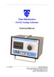
Time Electronics
1030 MicroCal
Voltage & Current Source.
Technical Manual
V3.2 01/11/10
Time Electronics Ltd
Botany Industrial Estate, Tonbridge, Kent, TN9 1RH
Tel: +44(0)1732 355993 Fax: +44(0)1732 770312
Email: [email protected]
Web Site: www.TimeElectronics.com
2
C ontents
1.
Introduc tion ................................................................................................3
1.1.
2.
S pec ific ations .............................................................................................4
2.1.
3.
4.
5.
General Description................................................................................... 3
Ordering Information and Optional Extras............................................... 5
C ontrols ......................................................................................................6
3.1.
Controls Diagram and Key ........................................................................ 6
3.2.
Description of Controls ............................................................................. 7
Operation ....................................................................................................8
4.1.
Voltage Ranges.......................................................................................... 8
4.2.
Output Voltages above 1V ........................................................................ 8
4.3.
Current Ranges .......................................................................................... 9
4.4.
Output Resistance ..................................................................................... 9
Applic ations .............................................................................................. 10
5.1.
Four Terminal Resistance Measurements ............................................. 10
5.2 Thermocouple Simulation .......................................................................... 11
6.
B attery R eplac ement & R ec harging ....................................................... 12
7.
C alibration ................................................................................................ 13
8.
9.
7.1.
Preparing for calibration ......................................................................... 13
7.2.
Module and Trimmer Location ................................................................ 14
Maintenanc e and R epair. ......................................................................... 15
8.1.
Dismantling the Instrument .................................................................... 15
8.2.
Battery Replacement. .............................................................................. 15
8.3.
Repair ....................................................................................................... 15
G uarantee & S ervic ing ............................................................................. 16
All Time Electronics' instruments are subject to continuous development and improvement and in consequence
may incorporate minor detail changes from the information contained herein.
1030 Technical Manual
Page |2
3
1. Introduc tion
•
3 Voltage Ranges up to 1 Volt
•
Extremely Compact
•
2 Current Ranges up to 100 mA
•
0.1% Accuracy
•
Uses a single PP3 Battery
1.1. General Description
The 1030 is a compact, low cost, portable voltage and current calibrator for general
purpose signal injection.
Three voltage ranges give adjustable output from 10uV to 1V, and two current ranges
give 10uA to 100mA.
The output is scaled directly and is varied by a high quality 10 turn dial.
The 1030 is simple to operate and does not require any standardisation prior to use.
The user need only switch on, check the battery condition, select the required range
and output.
The unit is powered from internal batteries and is supplied with a carry case making
the 1030 ideal for field or site use.
The 1030 is supplied with a leatherette carry case.
1030 Technical Manual
Page |3
4
2. S pec ific ations
Voltage Ranges:
0 - 1V (1mV resolution).
0 - 100 mV (100µV resolution).
0 - 10 mV (10µV resolution).
8 Volts (10mV resolution)
using external precision 1KΩ resistor supplied.
Current Ranges:
0 - 100mA (100µA resolution),
0 - 10mA (10µA resolution).
Accuracy:
1 Volt range:
100mV range:
10mV range:
100mA range:
10mA range:
8 Volt range:
± 0.1% of FS ± 30µV.
± 0.1% of FS ± 3µV.
± 0.2% of FS ± 0.3µV.
± 0.2% of FS ± 3µA.
± 0.2% of FS ± 0.3µA.
± 0.3% of FS.
Linearity:
0.15% of setting.
Temp. Coeff:
150 ppm of FS /ºC (Outside 18 to 28ºC).
Noise:
30 ppm of full scale.
Battery:
9V PP3 type. Approx. 60 hours life
depending on output current.
Nicad rechargeable available as an optional extra.
Battery Condition:
Continuously monitored by front panel indicator.
Output Polarity:
Positive or Negative, switch selectable.
A centre Off position is also provided, which shorts
the output terminals together.
Maximum Output Current:
1V, 100mV Ranges:
Typically 20 mA.
10mV Range:
Up to short circuit value although it should be
noted that loads of less than 1k ohm will give
greater than 0.1% error.
Maximum Output Voltage
(Current Ranges):
Output Protection:
1030 Technical Manual
8V.
The 1030 can withstand continuous short circuit
or open circuit on all ranges.
Page |4
5
Output Resistance:
0.2 ohm on 1V and 100mV ranges.
10 ohm on 10mV range.
1K ohm when using the current shunt resistor.
Dimensions:
115mm x 62mm x 55mm.
Carry Case:
A black carry case is supplied.
2.1. Ordering Information and Optional Extras
Order Code
Description
1030
MicroCal (Combined Voltage and Current Source)
1031
Rechargeable Battery Pack (NiCad Battery and 240V Mains Charger)
1032
Rechargeable Battery Pack (NiCad Battery and 110V Mains Charger)
9155
Factory (NPL Traceable) Calibration Certificate)
9110
UKAS Calibration Certificate (ISO 17025)
1030 Technical Manual
Page |5
6
3. C ontrols
8
1
3
2
4
5
7
6
3.1. Controls Diagram and Key
1) Black 4mm terminal
Negative output terminal.
2) Red 4mm terminal
Positive output terminal.
3) 3 Position switch
Selects Normal/Off/Reverse output
4) 6 Position rotary switch
Selects range and turns instrument on
5) 10 turn potentiometer
Selects required output
6) Potentiometer lock
Right position is free, left is locked.
7) Battery level indicator
Warns of battery failure
8) Recharge socket
For recharging Ni-Cad cell (if fitted)
1030 Technical Manual
Page |6
7
3.2. Description of Controls
1 / 2. Output Terminals
Output Voltage and Current is available on two front panel terminals which are suitable
for either wire compression or 4mm 'wander' plug insertion.
3. Polarity Switch
Normal or reverse polarity is selected by a toggle switch. The centre position is OFF
which provides an open circuit on the output terminals.
4. 6 way Position range switch
Switch Position
Switch Function
1
OFF
Voltage Ranges
2
0 – 1V (1mV resolution)
3
0 – 100mV (100uV resolution)
4
0 – 10mV (10uV resolution)
0 – 8V (10mV resolution), using external precision
1Kohm resistor (included)
Current Ranges
5
6
0 – 100mA (100uA resolution)
0 – 10mA (10uA resolution
5. 10 Turn fine adjust dial. Scaled 0-100. Linearly output from 0 – 100% of select
output range located on the top side of the 1030
6. 10 Turn dial potentiometer lock . Enables the output to be temporary locked.
7. Battery Level Indicator
Located on the top side of the 1030 this continuously monitors the battery voltage. A
minimum mark indicates when the batteries require recharging.
8. Recharge Socket
The mains recharger is a separate unit, the output of which is supplied via a flying lead
fitted with a non-reversible plug. Recharge time is between 12 and 14 hours.
CAUTION
UNDER NO CIRCUMSTANCES MUST AN ADDITIONAL VOLTAGE BE
CONNECTED IN SERIES WITH THE OUTPUT OF THE 1030 IN AN ATTEMPT TO
INCREASE THE VOLTAGE CAPABILITY AS THIS WILL CAUSE DAMAGE TO THE
OUTPUT CIRCUITRY.
1030 Technical Manual
Page |7
8
4. Operation
4.1. Voltage Ranges
Suggested operation procedure is as follows:
Select Off position on output switch.
Turn on, and select required range.
Check battery level indicator for high enough reading (see ‘Battery Replacement’).
Select required output on the ten turn potentiometer, which can then be locked by
pushing the lever at the bottom to the left. The ten turn potentiometer linearly adjusts
the output from zero to full scale on any range. The number of complete turns is
displayed in the dials window, parts of a turn are red on the inner scale, (calibrated 0-9
with 100 divisions), using the red indent as a pointer.
EXAMPLE: To set 56.2mV:
1) Select 100 mV range.
2) Turn dial until 5 appears in the centre of the window.
3) Set inner scale to 6.2.
The table below shows the effect of the dial on each range.
Range
Voltage Output.
1V
100 mV
10 mV
Current Output
100 mA
10 mA
NOTE:
1 Turn
1/10th of a Turn
1 Division
(1/100)
100 mV
10 mV
1 mV
10 mV
1 mV
100uV
1 mV
100uV
10uV
10 mA
1 mA
1 mA
100 uA
100 uA
10 uA
0.001V = 1mV = 1000uV
0.001A = 1mA = 1000uA
5) Switch output to Normal or Reverse as required.
4.2. Output Voltages above 1V
To use the 8V range, connect the supplied 1K ohm resistor across the output
terminals, and switch to the 10mA range. The 1030 will act as a voltage source, the
output being adjusted with the 10 turn dial, with a scale of 1 volt per turn up to a
maximum of about 8 volts with a good battery.
This allows the output to be set between 0V and ±8V with a 10mV resolution and an
accuracy of 0.3% of full scale.
1030 Technical Manual
Page |8
9
4.3. Current Ranges
On the current ranges, the drive voltage available at the terminals is governed by the
battery voltage. Care should be taken not to exceed the 1030 voltage limit, as large
errors will result if the load/current product exceeds the 1030 8V drive capability.
This can easily be checked by either measuring the voltage across the 1030’s
terminals when under load, or by checking that R x I is less than 8 volts.
4.4. Output Resistance
The table below illustrates how the voltage appearing at the output terminals of the
calibrator will be affected by load resistance:
Ratio of Load Resistance to Calibrator
Error in selected
Output Resistance
Output Voltage
1,000:1
0.1%
100:1
1.0%
10:1
9.0%
1:1
50.0%
1030 Technical Manual
Page |9
10
5. A pplic ations
5.1. Four Terminal Resistance Measurements
Accurate measurements of low ohm values, such as P.R.T, can be performed by using
the 1030 as a current source and measuring the voltage across the LOAD with a DVM.
From Ohms Law : V/I=R
Resistance vs Temperature Relationship for Platinum
Resistance Thermometer Detector Element (DIN 43760)
°C
-200
-180
-160
-140
-120
-100
-80
-60
-40
-20
0
20
40
Ω
18.48
27.08
35.53
43.87
52.11
60.25
68.33
76.33
84.27
92.16
100.00
107.79
115.54
°C
60
80
100
120
140
160
180
200
220
240
260
280
300
Ω
123.24
130.89
138.50
146.06
153.58
161.04
166.46
175.84
183.17
190.45
197.69
204.88
212.02
°C
320
340
360
380
400
420
440
460
480
500
520
540
560
Ω
219.12
226.17
233.17
240.13
247.04
253.90
260.72
267.49
274.22
280.90
287.53
294.11
300.65
°C
580
600
620
640
660
680
700
720
740
760
780
800
820
Using this technique, the current passed through to the resistor can be limited to a
known value, and lead resistance does not effect the accuracy of the readings.
1030 Technical Manual
P a g e | 10
Ω
307.15
313.59
319.99
326.35
332.66
338.92
345.13
351.30
357.42
363.50
369.53
375.51
381.45
11
5.2 Thermocouple Simulation
The 10mV range of the 1030 is ideal for simulation of all types of thermocouple. Just
find the voltage required from the British Standard tables, (common values given
below), and set up on the 1030’s dial. Do not forget to allow for the Cold Junction
temperature.
Thermocouples Temperature tables ITS90.
100°C
-50°C
-25°C
0°C
25°C
37°C
50°C
75°C
100°C
mV
mV
mV
mV
mV
mV
mV
mV
mV
NiCr/NiAl
Cu/Con
Fe/Con
Pt13%RH/Pt
Pt30%RH / Pt6%RH
Pt10%RH/Pt
NiCr/NiSi
-3.554
-1.889
-0.968
0.000
1.000
1.489
2.023
3.059
4.096
-3.379
-1.819
-0.940
0.000
0.992
1.486
2.036
3.132
4.279
-
-
-
0.000
1.277
1.902
2.585
3.918
5.269
-
-
-0.123
0.000
0.141
0.214
0.296
0.466
0.647
-
-
-
0.000
-0.002
-0.002
0.002
0.014
0.033
-
-
-0.127
0.000
0.143
0.216
0.299
0.467
0.646
-
-
-0.646
0.000
0.659
0.983
1.340
2.045
2.774
Temp °C
150°C
200°C
300°C
400°C
500°C
600°C
700°C
800°C
900°C
mV
mV
mV
mV
mV
mV
mV
mV
mV
NiCr/NiAl
Cu/Con
Fe/Con
Pt/Pt 13%RH
Pt30%RH / Pt6%RH
Pt10%RH/Pt
NiCr/NiSi
6.138
8.138
12.209
16.397
20.644
24.905
29.129
33.275
37.326
6.704
9.288
14.862
20.872
-
-
-
-
-
8.010
10.779
16.327
21.848
27.393
33.102
39.132
45.494
51.877
1.041
1.469
2.401
3.408
4.471
5.583
6.743
7.950
9.205
0.092
0.178
0.431
0.787
1.242
1.792
2.431
3.154
3.957
1.029
1.441
2.323
3.259
4.233
5.239
6.275
7.345
8.449
4.302
5.913
9.341
12.974
16.748
20.613
24.527
28.455
32.371
Temp °C
1000°C
1100°C
1200°C
1300°C
1400°C
1500°C
1600°C
1700°C
1800°C
mV
mV
mV
mV
mV
mV
mV
mV
mV
41.276
45.119
48.838
52.410
-
-
-
-
-
-
-
-
-
-
-
-
-
-
57.953
63.792
69.553
-
-
-
-
-
-
10.506
11.850
13.228
14.629
16.040
17.451
18.849
20.222
Temp °C
T/C
TYPE
Type K
Type T
Type J
Type R
Type B
Type S
Type N
T/C
TYPE
Type K
Type T
Type J
Type R
Type B
Type S
Type N
T/C
TYPE
Type K
Type T
Type J
Type R
Type B
Type S
Type N
NiCr/NiAl
Cu/Con
Fe/Con
Pt/Pt 13%RH
Pt30%RH / Pt6%RH
Pt10%RH/Pt
NiCr/NiSi
1030 Technical Manual
4.834
5.780
6.786
7.848
8.956
10.099
11.263
12.433
13.591
9.587
10.757
11.951
13.159
14.373
15.582
16.777
17.947
-
36.256
40.087
43.846
47.513
-
-
-
-
-
P a g e | 11
12
6. B attery R eplac ement & R ec harging
The battery capacity for rechargeable types is approx. 110mAH, whereas nonrechargeable types are approx. 70mAH. The 1030 circuitry takes 2mA, and will
operate over a battery voltage range of 7-12 volts. The battery life is primarily
dependent on the output current used. With low output currents, battery life can
exceed 60 hours, but when driving a 100mA output current, battery life is reduced to
about 50 minutes.
The battery should be replaced or recharged when the font panel battery level
indicator fails to register in the green section of the scale. The life of Ni-Cad batteries
is considerably reduced if they are subject to excessive discharging caused by
operating the instrument with an insufficient reading on the battery level indicator.
To replace the battery, unscrew the four screws in the rear cover of the instrument.
The battery is visible above the main P.C.B., (See Fig.1). Carefully remove the old
battery, and insert the new one. Screw the rear cover back on, and test the battery
condition.
BATTERY
Fig. 1
PP3 9V
To recharge a Ni-Cad battery, it is recommended that the instrument is turned off, in
order to reduce charging time to the 15hrs minimum. The charger is then plugged into
the recharge socket on the back. Note that it is NOT necessary to remove the battery
to recharge it. The battery will not be overcharged if the recharger is connected
continuously.
The charger is of the constant current type and should only be used when recharging
the internal Ni-Cad battery. The Ni-Cad battery can also be recharged from a 12V D.C.
supply by connecting the 1030 recharge socket to the 12V D.C. supply via a 300 Ohm,
1/4 watt resistor.
If it is required to power the 1030 from an external source, remove the internal battery,
and connect a 9 volt DC constant Voltage Power Unit into the recharge connector.
Note that the output is not isolated from the charger socket.
By powering the 1030 from an external source, it is possible to increase the voltage
limit on the current ranges to 12 volts.
1030 Technical Manual
P a g e | 12
13
7. C alibration
The instrument is calibrated before it leaves the factory and the calibration controls will
not normally require adjustment.
If re-adjustment is considered necessary, and the trimmer range is found to be
insufficient for recalibration, there is a fault with the instrument.
To calibrate the instrument a DVM of 0.1% accuracy is required. It should also be
capable of measuring:
10mV with 10uV resolution
100mV with 10uV resolution
1V with 100uV resolution
100mA with 100uA resolution
10mA with 10uA resolution
Calibration is carried out on the full scale and zero of the 100mV range. By correctly
calibrating this range, the other ranges are also calibrated.
7.1. Preparing for calibration
1
Turn instrument out Off.
2
Switch to 100mV range.
3
Remove cap from top of range switch knob, and loosen the screw inside.
The range switch knob should then be removed.
4
Undo the nut which attaches the output switch to the body of the 1030.
5
Carefully unscrew the rear cover.
6
The main P.C.B. can now be gently eased out of the case.
7
If the module is to be replaced, it can be unplugged now, and the new one fitted.
The 1030 will then need to be recalibrated.
8
The full scale calibration trimmer is next to the module, on the left looking down
at the P.C.B. from the component side. The zero calibration trimmer is in a
corresponding position on the right of the P.C.B. (see Fig. 2).
9
Plug the DVM into the output terminals and turn the output switch to Normal.
10
Turn the output adjustment pot. to zero. The 1030’s output will not go negative,
so the ‘ZERO’ trimmer should be set by first adjusting for a positive output, then
slowly turning back to zero. The zero for the instrument is then set up correctly
1030 Technical Manual
P a g e | 13
14
7.2.
Module and Trimmer Location
Fig. 2
11
Turn the output adjustment pot. to full scale, and adjust the full scale calibration
trimmer until the DVM reads 100mV.
The full scale for the instrument is then set up correctly.
The other ranges do not normally require calibration, and therefore are not fitted
with trimmers.
Should calibration become necessary, adjust or replace the resistors listed
below.
12
10mV F.S.
R6
10mA F.S.
R9
100mA F.S.
R5
The instrument can now be reassembled.
1030 Technical Manual
P a g e | 14
15
8. Maintenanc e and R epair.
8.1. Dismantling the Instrument
Remove rubber protection boot and then removal of four 6BA screws enables the
cover to be taken off which provides access to all parts of the instrument.
8.2. Battery Replacement.
Remove protection cover and then removal of four screws enables the cover to be
taken off which provides access to the battery lift battery out of holder and careful
disconnect battery connector, connect new battery and replace into case replace case
cover and recheck battery level.
8.3.
Repair
NOTE: No repair work should be undertaken by the customer while the
instrument is under warranty as such work may render the warranty invalid.
Certain of the precision components used in this instrument are not readily available
and make repairs by the customer difficult if these components are damaged.
Overload conditions can cause a unit failure which will be indicated by one of the
following conditions:
a) Instrument inoperative and battery level indicator at zero.
b) Battery level indicator displaying but no output at the output terminals.
1030 Technical Manual
P a g e | 15
16
9. G uarantee & S ervic ing
Guarantee Period
This unit is guaranteed against defects in materials and workmanship for a period of
one year from its delivery to the customer.
We maintain comprehensive after sales facilities and the unit can, if necessary be
returned to us for servicing. During this period, Time Electronics Ltd will, at its
discretion, repair or replace the defective items. For servicing under guarantee, the
instrument type and serial number must always be quoted, together with details of any
fault and the service required. The purchaser of the instrument must prepay all
shipping charges. Time Electronics Ltd will pay return shipping charges.
This guarantee is void if servicing has been attempted by an unauthorised person or
agent. If, during the guarantee period, failure is due to misuse or abuse of the unit, the
repair will be put in hand without delay and charged unless other instructions are
received.
Please note that if you require a new UKAS Certificate during the warranty period, this
will be charged at the current rate on our price list.
Service After Guarantee Period
Even after the guarantee period has expired, Time Electronics Ltd., can still service
your instrument. As the manufacturer, we have the specialised knowledge needed to
keep your instrument in peak condition and we also maintain a comprehensive spare
parts service.
Please enclose details of the service required and your full company details including a
contact name when returning for servicing.
Returning Instruments
When returning instruments, please ensure that they have been adequately packed,
preferably in the original packing supplied. Time Electronics Ltd will not accept
responsibility for units returned damaged. Please ensure that all units have details
of the service required and all relevant paperwork.
Send the instrument, shipping charges paid to:-
Time Electronics Ltd
Botany Industrial Estate, Tonbridge, Kent, TN9 1RH
Tel: +44(0)1732 355993 Fax: +44(0)1732 770312
Email: [email protected]
Web Site: www.TimeElectronics.com
Disposal of your old equipment
1. When this crossed-out wheeled bin symbol is attached to a product it means the
product is covered by the European Directive 2002/96/EC.
2. All electrical and electronic products should be disposed of separately from the
municipal waste stream via designated collection facilities appointed by the
government or the local authorities.
3. The correct disposal of your old appliance will help prevent potential negative
consequences for the environment and human health.
4. For more detailed information about disposal of your old appliance, please contact
your city office, waste disposal service or return to Time Electronics.
1030 Technical Manual
P a g e | 16