1
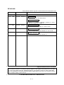
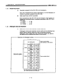
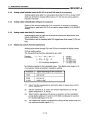
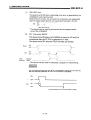
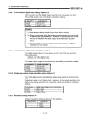
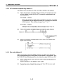
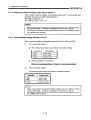
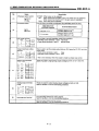
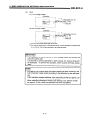
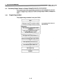
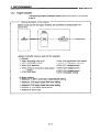
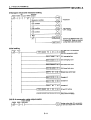
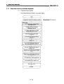
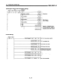
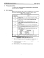
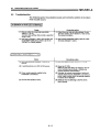
Analog Input/Output Module Type A1S63ADA
,
User s Manual
MODEL
A1S63ADA-U-E
MODEL
CODE
13JE30
Analog Input/Output Module Type A1S63ADA
,
User s Manual
IB(NA)-66435-D(0402)MEE
HEAD OFFICE : 1-8-12, OFFICE TOWER Z 14F HARUMI CHUO-KU 104-6212,JAPAN
NAGOYA WORKS : 1-14 , YADA-MINAMI 5-CHOME , HIGASHI-KU, NAGOYA , JAPAN
When exported from Japan, this manual does not require application to the
Ministry of Economy, Trade and Industry for service transaction permission.
Specifications subject to change without notice.
Mitsubishi Programmable Logic Controller
• SAFETY PRECAUTIONS •
(Always read these instructions before using this equipment.)
When using this equipment, thoroughly read this manual and the associated manuals introduced in this
manual. Also pay careful attention to safety and handle the equipment properly.
These precautions apply only to this equipment. For the safety precautions of the PLC system, please
read the user's manual for the CPU module to use.
These zSAFETY PRECAUTIONSz classify the safety precautions into two categories: "DANGER" and
"CAUTION".
!
DANGER
Procedures which may lead to a dangerous condition and cause
death or serious injury if not carried out properly.
!
CAUTION
Procedures which may lead to a dangerous condition and cause
superficial to medium injury, or physical damage only, if not
carried out properly.
Depending on circumstances, procedures indicated by
results.
!
CAUTION may also be linked to serious
In any case, it is important to follow the directions for usage. Store this manual in a safe place so that you
can take it out and read it whenever necessary. Always forward it to the end user.
[DESIGN PRECAUTIONS]
!
DANGER
• Configure a safety circuit on the outside of the PC so that the entire system works to a safe side
even when the external power failure occurs or PC main unit fails.
An erroneous output or operation may result in an accident.
!
CAUTION
• Use the PC in the environment given in the general specifications section of the applicable CPU
module user's manual.
Failure to do so may result in electric shock, fire, or erroneous operation or may damage or
degrade the equipment.
• Do not bundle, or install, the control cables with, or near, the main circuit and power cables.
Keep them at least 100 mm (3.9 inch) away from such cables.
Noise may cause erroneous operation.
• At power ON/OFF, voltage or current may instantaneously be output from the output terminal of
this module. In such case, wait until the analog output becomes stable to start controlling the
external device.
A-1
[INSTALLATION PRECAUTIONS]
!
CAUTION
• Insert the tabs at the bottom of the module into the holes in the base module before installing the
module. Be sure to install the module in the base module with screws tightened to the specified
torque.
Improper installation may cause erroneous operation, accident, or the module to fall out.
• Do not directly touch the module's conductive parts.
Doing so could cause malfunction or trouble in the module.
[WIRING PRECAUTIONS]
!
CAUTION
• If noise generates frequently, ground the AG and FG terminals using the PC dedicated class-D
ground (class-three ground) or higher.
Failure to do so may result in erroneous operation.
• Confirm the rated voltage and terminal arrangement of the module before wiring it to the PC.
If a power supply of different rating is connected or a wiring is performed erroneously, fire or
accident may result.
• Tighten the terminal screws to the specified torque.
Loose terminal screws may cause a short circuit or erroneous operation.
If excessively tightened, the terminal screws may be damaged, and cause a short circuit or
erroneous operation.
• Be sure that cuttings, wire chips, or other foreign matter do not enter the module.
Foreign matter may start a fire or cause an accident or erroneous operation.
A-2
[STARTING AND MAINTENANCE PRECAUTIONS]
!
CAUTION
• Do not touch live terminals.
It may cause erroneous operation.
• Be sure to shut off all phases of the external power supply used by the system before cleaning.
Not doing so can cause the module to fail or malfunction.
• Do not disassemble or rebuild the module.
It may cause accidents, erroneous operation, injury, or fire.
• Be sure to shut off all phases of the external power supply used by the system before mounting
or dismounting the module to or from the panel.
Not doing so can cause the module to fail or malfunction.
• Before handling the module, make sure to touch a grounded metal object to discharge the static
electricity from the human body.
Failure to do say cause a failure or malfunctions of the module.
[OPERATING PRECAUTIONS]
!
CAUTION
• Do not output (ON) "Use Prohibited" signals from the PC CPU to the special module.
Doing so could erroneously operate the PC system.
[DISPOSAL PRECAUTIONS]
!
CAUTION
• When disposing of this equipment, handle it as industrial waste.
A-3
REVISIONS
*The manual number is given on the bottom left of the back cover.
Print Date
*Manual Number
Revision
Sep., 1993
IB (NA) - 66435-A
First edition
Dec., 1999
IB (NA) - 66435-B
ADDITION
Safety Precautions and Guarantee
Partial Correction
Chapter 2 (1), Chapter 2 Remark, section 3.1, 3.2.3,
4.1.2, 4.2, 4.3.2, 5.1.1, App. 3
Oct., 2002
IB (NA) - 66435-C
Partial Correction
Chapter 2 Remark, section 3.1, 3.2.2, 4.3.2
Feb., 2004
IB (NA) - 66435-D
Partial Correction
SAFETY PRECAUTIONS, section 3.1, 3.5, 4.3.2
Sep., 2005
IB (NA) - 66435-E
Partial Correction
SAFETY PRECAUTIONS, section 5.1
Japanese Manual Version SH-3528-H
This manual confers no industrial property rights or any rights of any other kind, nor does
it confer any patent licenses. Mitsubishi Electric Corporation cannot be held responsible
for any problems involving industrial property rights which may occur as a result of using
the contents noted in this manual.
© 1993 MITUBISHI ELECTRIC CORPORATION
A–4
Conformance to the EMC Directive/Low Voltage Directive
When incorporating the Mitsubishi PLC into other machinery or equipment and keeping
compliance with the EMC and low voltage directives, refer to Chapter 3, "EMC Directives and Low
Voltage Directives" of the User’s Manual (Hardware) included with the CPU module or base unit
used.
The CE logo is printed on the rating plate on the main body of the PLC that conforms to the EMC
directive and low voltage instruction.
By making this product conform to the EMC directive and low voltage instruction, it is not
necessary to make those steps individually.
A–7
5. PROGRAMMING
5.
MELSEC-A
PROGRAMMING
When utilizing the program example introduced in this chapter for an actual
system, fully verify that there are no problems in controllability in the target
system.
5.1
Converting Analog Voltage/Current to Digital Values (A-D Conversion)
This section gives the programming procedures and examples for the conversion of analog input values (voltage/current) on CH1 and CH2 to digital
values.
5.1.1
Programming procedure
The programming procedure is as given below.
Start
Offset/gain values and resolution setting
. . . Not necessary when these are
set by the user.
Initial setting
A-D conversion enable/disable setting
(address 0)
Averaging time/count setting
(addresses 2 and 3)
A-D conversion averaging setting
(address 1)
A-D conversion completion flag reading
(address 15)
Digital value reading
(addresses 11 and 12)
Error detection (X02, address 16)
Error reset (Y12)
Complete
POINT
Among various types of processing of the special function modules, an
access from the PC CPU takes priority.
If an access from the PC CPU to the buffer memory of the special function modules is performed frequently, not only the scanning time of the
PC CPU will be extended but also the various types of processings of
the special function modules will be delayed.
Perform the access from the PC CPU to the buffer memory by
FROM/TO instruction only when necessary.
5–1
WARRANTY
Please confirm the following product warranty details before using this product.
1. Gratis Warranty Term and Gratis Warranty Range
If any faults or defects (hereinafter "Failure") found to be the responsibility of Mitsubishi occurs during use of the product
within the gratis warranty term, the product shall be repaired at no cost via the sales representative or Mitsubishi Service
Company.
However, if repairs are required onsite at domestic or overseas location, expenses to send an engineer will be solely at
the customer’s discretion. Mitsubishi shall not be held responsible for any re-commissioning, maintenance, or testing onsite that involves replacement of the failed module.
[Gratis Warranty Term]
The gratis warranty term of the product shall be for one year after the date of purchase or delivery to a designated
place.
Note that after manufacture and shipment from Mitsubishi, the maximum distribution period shall be six (6) months, and
the longest gratis warranty term after manufacturing shall be eighteen (18) months. The gratis warranty term of repair
parts shall not exceed the gratis warranty term before repairs.
[Gratis Warranty Range]
(1) The range shall be limited to normal use within the usage state, usage methods and usage environment, etc.,
which follow the conditions and precautions, etc., given in the instruction manual, user's manual and caution labels
on the product.
(2) Even within the gratis warranty term, repairs shall be charged for in the following cases.
1. Failure occurring from inappropriate storage or handling, carelessness or negligence by the user. Failure caused
by the user's hardware or software design.
2. Failure caused by unapproved modifications, etc., to the product by the user.
3. When the Mitsubishi product is assembled into a user's device, Failure that could have been avoided if functions
or structures, judged as necessary in the legal safety measures the user's device is subject to or as necessary
by industry standards, had been provided.
4. Failure that could have been avoided if consumable parts (battery, backlight, fuse, etc.) designated in the
instruction manual had been correctly serviced or replaced.
5. Failure caused by external irresistible forces such as fires or abnormal voltages, and Failure caused by force
majeure such as earthquakes, lightning, wind and water damage.
6. Failure caused by reasons unpredictable by scientific technology standards at time of shipment from Mitsubishi.
7. Any other failure found not to be the responsibility of Mitsubishi or that admitted not to be so by the user.
2. Onerous repair term after discontinuation of production
(1) Mitsubishi shall accept onerous product repairs for seven (7) years after production of the product is discontinued.
Discontinuation of production shall be notified with Mitsubishi Technical Bulletins, etc.
(2) Product supply (including repair parts) is not available after production is discontinued.
3. Overseas service
Overseas, repairs shall be accepted by Mitsubishi's local overseas FA Center. Note that the repair conditions at each FA
Center may differ.
4. Exclusion of loss in opportunity and secondary loss from warranty liability
Regardless of the gratis warranty term, Mitsubishi shall not be liable for compensation of damages caused by any cause
found not to be the responsibility of Mitsubishi, loss in opportunity, lost profits incurred to the user by Failures of Mitsubishi
products, special damages and secondary damages whether foreseeable or not , compensation for accidents, and
compensation for damages to products other than Mitsubishi products, replacement by the user, maintenance of on-site
equipment, start-up test run and other tasks.
5. Changes in product specifications
The specifications given in the catalogs, manuals or technical documents are subject to change without prior notice.
6. Product application
(1) In using the Mitsubishi MELSEC programmable logic controller, the usage conditions shall be that the application will
not lead to a major accident even if any problem or fault should occur in the programmable logic controller device, and
that backup and fail-safe functions are systematically provided outside of the device for any problem or fault.
(2) The Mitsubishi programmable logic controller has been designed and manufactured for applications in general
industries, etc. Thus, applications in which the public could be affected such as in nuclear power plants and other
power plants operated by respective power companies, and applications in which a special quality assurance system
is required, such as for Railway companies or Public service purposes shall be excluded from the programmable logic
controller applications.
In addition, applications in which human life or property that could be greatly affected, such as in aircraft, medical
applications, incineration and fuel devices, manned transportation, equipment for recreation and amusement, and
safety devices, shall also be excluded from the programmable logic controller range of applications.
However, in certain cases, some applications may be possible, providing the user consults their local Mitsubishi
representative outlining the special requirements of the project, and providing that all parties concerned agree to the
special circumstances, solely at the users discretion.
Analog Input/Output Module Type A1S63ADA
,
User s Manual
MODEL
A1S63ADA-U-E
MODEL
CODE
13JE30
Analog Input/Output Module Type A1S63ADA
,
User s Manual
IB(NA)-66435-E(0509)MEE
HEAD OFFICE : TOKYO BUILDING, 2-7-3 MARUNOUCHI, CHIYODA-KU, TOKYO 100-8310, JAPAN
NAGOYA WORKS : 1-14 , YADA-MINAMI 5-CHOME , HIGASHI-KU, NAGOYA , JAPAN
When exported from Japan, this manual does not require application to the
Ministry of Economy, Trade and Industry for service transaction permission.
Specifications subject to change without notice.
Mitsubishi Programmable Logic Controller