1
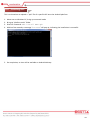
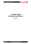
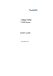
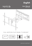
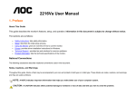
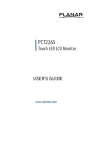
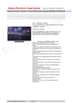
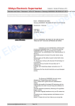
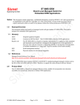
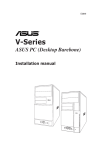
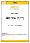
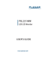
Panel PC PPC-ARM Always at the forefront of innovation User Manual 1 Copyright This publication contains information that is protected by copyright. No part of it may be reproduced in any form or by any means or used to make any transformation adaptation without the prior written permission from the copyright holders. This publication is provided for informational purposes only. The manufacturer makes no representations or warranties with respect to the contents or use of this manual and specifically disclaims any express or implied warranties of merchantability or fitness for any particular purpose. The user will assume the entire risk of the use or the results of the use of this document. Further, the manufacturer reserves the right to revise this publication and make changes to its contents at any time, without obligation to notify any person or entity of such revisions or changes. © 2011. All Rights Reserved. Trademarks All trademarks and registered trademarks of products appearing in this manual are the properties of their respective holders. FCC and DOC Statement on Class A This equipment has been tested and found to comply with the limits for a Class A digital device, pursuant to Part 15 of the FCC rules. These limits are designed to provide reasonable protection against harmful interference when the equipment is operated in a residential installation. This equipment generates, uses, and can radiate radio frequency energy and, if not installed and used in accordance with the instruction manual, may cause harmful interference to radio communications. However, there is no guarantee that interference will not occur in a particular installation. If this equipment does cause harmful interference to radio or television reception, which can be determined by turning the equipment off and on, the user is encouraged to try to correct the interference by one or more of the following measures: Reorient or relocate the receiving antenna. Increase the separation between the equipment and the receiver. Connect the equipment into an outlet on a circuit different from that to which the receiver is connected. Consult the dealer or an experienced radio TV technician for help. Notice: 1. The changes or modifications not expressly approved by the party responsible for compliance could void the user’s authority to operate the equipment. 2. Shielded interface cables must be used in order to comply with the emission limits. 2 Warranty 1. Warranty does not cover damages or failures that are raised from misuse of the product, inability to use the product, unauthorized replacement or alteration of components and product specifications. 2. The warranty is void if the product has been subject to physical abuse, improper installation, modification, accidents or unauthorized repair of the product. 3. Unless otherwise instructed in this user’s manual, the user may not, under any circumstances, attempt to perform service, adjustments or repairs on the product, whether in or out of warranty. It must be returned to the purchase point, factory or authorized service agency for all such work. 4. We will not be liable for any indirect, special, incidental or consequential damages to the product that has been modified or altered. Static Electricity Precautions It is quite easy to inadvertently damage your PC, system board, components or devices even before installing them in your system unit. Static electrical discharge can damage computer components without causing any signs of physical damage. You must take extra care in handling them to ensure against electrostatic build-up. 1. To prevent electrostatic build-up, leave the system board in its anti-static bag until you are ready to install it. 2. Wear an antistatic wrist strap. 3. Do all preparation work on a static-free surface. 4. Hold the device only by its edges. Be careful not to touch any of the components, contacts or connections. 5. Avoid touching the pins or contacts on all modules and connectors. Hold modules or connectors by their ends. Important: Electrostatic discharge (ESD) can damage your processor, disk drive and other components. Perform the upgrade instruction procedures described at an ESD workstation only. If such a station is not available, you can provide some ESD protection by wearing an antistatic wrist strap and attaching it to a metal part of the system chassis. If a wrist strap is unavailable, establish and maintain contact with the system chassis throughout any procedures requiring ESD protection. 3 Safety Measures To avoid damage to the system: • Use the correct AC input voltage range should an external AC/DC adaptor is employed. To reduce the risk of electric shock: • Unplug the power cord before removing the system chassis cover for installation or servicing. After installation or servicing, cover the system chassis before plugging the power cord. Battery: • Danger of explosion if battery incorrectly replaced. • Replace only with the same or equivalent type recommend by the manufacturer. • Dispose of used batteries according to local ordinance. Before Using the System Before using the system, prepare basic system components. If the system comes as a barebone; that is, none of the key components, including processor, memory, and hard drive has been pre-installed as part of your purchase, you will need to at least ensure a compatible counterpart is located and installed. You will also need a few external system peripherals intended for the use of the system, a common pool with at least a keyboard, a mouse, and a monitor is thus suggested. 4 Table of Content Copyright .................................................................................................................................................................... 2 Trademarks .................................................................................................................................................................... 2 FCC and DOC Statement On Class A.............................................................................................................................. 2 Warranty ........................................................................................................................................................................ 3 Static Electricity Precautions ......................................................................................................................................... 3 Safety Measures ............................................................................................................................................................ 4 Before Using the System ............................................................................................................................................... 4 Table of Content ............................................................................................................................................................ 5 Chapter 1 General Information 1.1 Main Feature ........................................................................................................................................................... 7 1.2 Specifications ....................................................................................................................................................... 8 1.3 System Layout ................................................................................................................................................... 9 1.4 Indications & Features .................................................................................................................................... 10 1.5 Back Panel Connectors ................................................................................................................................... 11 Chapter 2 Jumper Setting 2.1 Before You Begin ...................................................................................................................................... 13 2.2 Precautions......................................................................................................................................................... 13 2.3 Open Up Back Cover ........................................................................................................................................... 14 2.4 Internal Connectors ........................................................................................................................................... 15 Chapter 3 Android Software Access 3.1 Preparing Tools .............................................................................................................................................. 20 3.2 Loading OTG Driver ..................................................................................................................................... 21 3.3 Open USB Debug Port ...................................................................................................................................... 22 3.4 Installing APP .................................................................................................................................................. 24 5 Chapter 1 General Information 6 1.1 Main Feature ARM®-Based Panel PC PPC-ARM is a general purpose ARM®-Based Panel PC with Freescale i.MX6 Dual/Quad Core 1GHz Processor, 1GB DDR3 Memory, 4GB eMMC as onboard storage, and a wide variety sizes of panel and touch from 10.1” to 21.5”, suggesting scalable customization for users to maximize the application coverage. Outstanding Freescale i.MX6 Graphic Performance The i.MX6 processors are designed for next-generation consumer, industrial, and automotive applications. The power-efficient processing capabilities of the ARM Cortex-A9 architecture with outstanding 3D and 2D graphics, as well as high-definition video, create a new level of multimedia performance to enable an unlimited next-generation user experience, especially over Android in which some smooth graphic performance against user’s touch triggering is demanded. Fanless With Inherent Low Power Consumption The extremely low power consumption from i.MX6 processor benefits from the fanless nature of the built-in embedded board, that being propagated to the design of PPC-ARM, minimizes the system slimness with greater endurance against higher average environment temperature and more spatial limitation. Such a nature also suggests no operation noise, a level that any noise-critical application would bear to put up with. List of Key Features Freescale iMX6 Dual-Lite ARM® Cortex™-A9 Processor 10.1" ~ 21.5" Full Range Panel Size Full Flat P-CAP Multi Touch Panel Fanless & Low Power Consumption Internal WiFi+ BT Module On Request Slim and Compact Metal Housing Onboard 4GB eMMC with Android 4.4 7 1.2 Specifications System Motherboard BNX-FMX3 Process Freescale ARM® CortexTM-A9 Dual-Lite 1GB Processor(Default) Freescale ARM® CortexTM-A9 Quad-Core 1GB Processor(Option) Display Memory Onboard 1GB DDR3 1066MHz Operation System Android 4.4 (Default) / Ubuntu 12.04 (Optional) 10.4” 12.1” 15” 10.1” 15.6” 21.5” 1024x768 1024x768 1024x768 1280x800 1366x768 1920x1080 Size/Type Resolution 4:3 Brightness(cd/m2) 350 350 16:9 300 Touch interface Storage 300 250 P-CAP touch eMMC Onboard 4GB eMMC SD Micro-SD Card Slot Connectivity 350 10/100/1000 Mbps Communication 802.11a/b/g/n, Bluetooth, 3G / 4G module (Optional) Power Environment I/O 1x Power Switch with LED indicator, 1x DC-in Jack, 1x Line-out, 1x Mic-in, 1x HDMI 1x VGA (Optional), 1x RJ45 LAN, 2x USB 2.0, 1x Micro-USB OTG, 1x RS232(Optional) 2x 8Ω/1W Speaker, 1x RF Antenna, 1x 3G/4G Antenna Input 12Vdc Power-In / 100-240Vac, 50-60Hz Consumption 15W Operating Temp. 0oC to 50oC Storage Temp. -20oC to 60oC Humidity 10% to 90% (Operating, non-condensing) 8 1.3 System Layout Figure 1.1: System Layout of PPC-ARM 9 1.4 Indicators & Features ►Front View Full Flat P-CAP Touch Screen ►Rear View 1. 2. 3. 4. Micro-SD Slot WiFi / Bluetooth Antenna Cutout 3G/4G Antenna Cutout Standard VESA Mount (75x75mm) 10 1.5 Back Panel Connectors 1. 2. 3. 4. 5. 6. 7. USB OTG Port 2* USB 2.0 10/100/1000 Ethernet HDMI Audio Output 12V DC-in Phoenix Connector Power Switch 11 Chapter 2 Preparation 12 2.1 Before You Begin A stable and clean working environment are essential. Dust and dirt can get into components and cause a malfunction. Use containers to keep small components separated. Adequate lighting and proper tools can prevent you from accidentally damaging the internal components. Most of the procedures that follow require only a few simple tools, including the following: A Philips screwdriver A flat-tipped screwdriver A set of jewelers Screwdrivers A grounding strap An anti-static pad Using your fingers can disconnect most of the connections. It is recommended that you do not use needle-nosed pliers to disconnect connections as these can damage the soft metal or plastic parts of the connectors. Before working on internal components, make sure that the power is off. Ground yourself before touching any internal components, by touching a metal object. Static electricity can damage many of the electronic components. Humid environment tend to have less static electricity than dry environments. A grounding strap is warranted whenever danger of static electricity exists. Computer components and electronic circuit boards can be damaged by discharges of static electricity. Working on the computers that are still connected to a power supply can be extremely dangerous. Follow the guidelines below to avoid damage to your computer or yourself: Always disconnect the unit from the power outlet whenever you are working inside the case. If possible, wear a grounded wrist strap when you are working inside the computer case. Alternatively, discharge any static electricity by touching the bare metal chassis of the unit case, or the bare metal body of any other grounded appliance. Hold electronic circuit boards by the edges only. Never touch the components on the board unless it is necessary to do so. Do not flex or stress the circuit board. Leave all components inside the static-proof packaging that they shipped with until they are ready for installation. Use correct screws and do not over tighten screws. 13 In case a particular cable, switch, or module is out of order, a replacement or proper adjustment upon the integrated parts may be required. To access all these integrated parts within PPC-ARM, you need to open up the back cover first. To do so, please make sure the cautious reminder in section 2.1 has been seriously taken into account prior to any further step below. Turn your PPC-ARM upside down, that is, placing the panel side on the table. It is not necessary to open up the back cover if it is to add/remove/swap a Micro-SD card. The Micro-SD slot can be found on the side of this back cover. Please refer to the Micro-SD Card section for details. Remove the 6 screws as indicated in the places below, prior to any moving of the back cover. It is necessary to push the lower side (the side attached to I/O connectors) upwards, then pull this back cover out of the place. Securing all the screws is essential for they would be re-used for the restoration of the back cover, after all preparation procedures are completed. Remove the 6 screws Life up the side of arrow (this side up first) Please be advised that, if the unit comes to you with wireless module installed and the antenna (1 or 2 of them) mounted, the antenna is actually attached directly to the back cover (as in the picture above), while the antenna cables are connected on the internal wireless module. It is our job to remind you of the existence of both parts and special carefulness is to be expected while taking the back cover off the unit, where the antenna cable might be damaged by inadvertent handling of this back cover. To avoid breaking off the cable, after the back cover is lifted up, please make sure the antenna cable is detached from the wireless module before the back cover is moved away. 14 Power Input Phoenix Connector Pin Definition Pin Definition 1 2 V- V+ Type-A USB 2.0 Pin Definition Pin Definition 1 3 Vcc (5V) D+ 2 4 DGND 15 RJ45 LAN Connector Pin Definition Pin Definition 1 3 5 7 TX+ RX+ NC NC 2 4 6 8 TXNC RXNC Pin Definition Pin Definition 1 3 5 7 9 DCD TXD GND RTS RI 2 4 6 8 RXD DTR DSR CTS DB9 RS-232 Connector (Optional) 16 VGA (Optional) Pin Definition Pin Definition 1 3 5 7 9 11 13 15 RED BLUE GND GREEN_RTN KEY/PWR ID0/RES HSync ID3/SCL 2 4 6 8 10 12 14 GREEN ID2/RES RED_RTN BLUE_RTN GND ID1/SDA VSync HDMI Pin Definition Pin Definition 1 2 3 4 5 6 7 8 9 10 TMDS data 2+ TMDS data 2 Shield TMDS data 2TMDS data 1+ TMDS data 1 Shield TMDS data 1TMDS data 0+ TMDS data 0 Shield TMDS data 0TMDS clock + 11 12 13 14 15 16 17 18 19 TMDS clock Shield TMDS clockCEC NC DDC clock DDC data Ground +5V Power Hot Plug Detect 17 OTG Pin Definition Pin Definition 1 3 5 VCC TX GND 2 4 RX NC Audio Power Switch 18 Chapter 3 Android Software Access 19 3.1 Preparing Tools Some hardware and software are to be prepared before further jobs are proceeded. Hardware Requirement: 1. 1* Windows PC: NB (Notebook) or Desktop PC, Windows-Based. 2. 1* USB Type-A to micro USB cable Software Requirement: 1. Platform-tools 2. AdbDriverInstaller.exe 3. Image Files 20 3.2 Loading OTG Driver Knowing how to connecting PPC-ARM with a Windows computer (Compatible Windows would be any of Windows-XP/7/8, 32/64bit) is essential. Most users would use the onboard eMMC as their primary OS storage, leaving the Micro-SD as the media for data recording or exchange. As eMMC is mounted on the board, using USB OTG port has become the standard and the only approach to upload a new or refurbished image file onto eMMC. However, if a user chooses to use Micro-SD as the primary OS storage, Micro-SD card can be removed from the card slot, and the image file can be replaced by using image writer tool running on Windows. This part is subject to the software being used as the image writer, and is not covered in this user’s manual as process might vary. Please refer to the following procedure to activate OTG port. 1. Connect the OTG port of PPC-ARM to any USB port of one Windows computer. 2. Turn on PPC-ARM 3. Execute this tool (AdbDriverInstaller.exe) on Windows: 4. Windows will automatically detect PPC-ARM and produce a list with “Android Composite ADB Interface” as below. Please click on it to select it, and press “Install” to start driver installation. 21 3.3 Open USB Debug Port USB Debug Port needs to be activated within Android prior to any debugging or software session. It is assumed that the OTG driver in Section 3.1 has been loaded. 1. Turn on the power of PPC-ARM. Once Android desktop is available to your operation, find the setting icon and Click on it. 2. Find on the left side of the pane “about Tablet” as 3. Make 5~10 times of quick clicks on “Build Number” until “Developer options” shows at Left side. 4. Click on “Developer options ” 5. Select “USB debugging” as 6. Click “OK” to open USB debug port 7. Hereby it is assumed that the back cover of PPC-ARM has been removed. Find the switch panel as below. 8. Please move the switch No.6 to OFF position. 9. Connect PPC-ARM with a Windows PC via USB OTG port. 10. Turn on PPC-ARM. 11. Open “Image Files” file on Windows PC. 22 12. Click “MfgTool2.exe” until device is connected. 13. Click “Start“ to Upgrade Image and waiting for 4~5 minutes. 14. When finish software upgrade, click “stop “. 15. Remove PPC-ARM adapter to shut it down, and move switch NO.6 to ON position. 16. Restore the back cover. 23 4.4 Installing APP This is to show how to upload a “.apk” file of a specific APP onto the Android platform. 1. 2. 3. 4. Move over to Windows PC, bring up command mode Bring up “platform-tools” folder Give this command: adb install XXX.apk Within a few seconds, a message “Success” will pop up, indicating the installation is successful. 5. On completion, an icon will be available on Android desktop. 24