1
Operation manual
VULKAN
Extrusion Pumps
Type: ❍ 49 … …
❍ 78 … …
❍ 134 … …
❍ 269 … …
❍ 521 … …
❍ 680 … …
Serial-No.
……………………
Translation of the original operation manual Extrusion pumps
EXP · DBK · en · 04.12 · jw
Contents
1
Contents
1.1 Preface
This User’s Handbook must always be available to operating staff
The operating authority of the equipment must
ensure, that a user`s handbook is available to
the operator, in a language which he understands
Dear customer!
Thank you for your decision to purchase a
equipment.
In the user’s manual you can find all information required
for the proper handling of your
extrusion pump.
However, for safe operation there are further essential
details which you should adhere:
Please read and observe the guidelines valid for your
country. In Germany the "Richtlinien für Flüssigkeitsstrahler" (Guidelines for liquid sprayers), Published by:
Hauptverband der Gewerblichen Berufsgenossenschaften,
are valid.
1.2 Table of Contents
page
1Contents................................................................. 3
1.1Preface.................................................................... 3
1.2 Table of Contents.................................................... 3
2Safety..................................................................... 4
2.1
2.2
2.3
2.4
2.5
2.6
2.7
2.8
2.9
2.10
3
4
Description of symbols............................................ 4
Dangers arising from the equipment....................... 4
Application of the machine...................................... 4
Machine surroundings and Installation Site............ 5
Sources of danger................................................... 5
Operating staff......................................................... 6
Behaviour in case of emergency............................. 7
Protective equipment.............................................. 7
Handling of the machine and auxiliary materials..... 7
Transportation of the machine and additional
equipment............................................................... 7
Machine description.............................................. 9
Erection and Assembly....................................... 10
Manufacturer’s notes and operating guidelines for coating
and pumping materials should be observed at all times.
4.1Erection................................................................. 10
4.2Assembly............................................................... 10
Since
extrusion pumps, mainly with rams and lifts,
are installed in plants, the operating instructions of such
devices and the accessories applied in this connection
must also be observed and adhered to.
5.1
5.2
Preparation............................................................ 11
First cleaning......................................................... 11
In principle no method of working should be exercised
which impairs the safety of
products and the operating personnel.
6.1
6.2
6.3
Spraying/pumping material................................... 12
Interruption of work .............................................. 12
Cleaning /Change of material................................ 12
We wish you much success and good working results for
the application of your extrusion pump.
WIWA Wilhelm Wagner GmbH & Co.KG
7.1Inspection.............................................................. 13
7.2 Maintenance plan.................................................. 13
Copyright
© 2009 WIWA
Copyright ownership for this user manual remains with
WIWA WILHELM WAGNER GmbH & Co. KG
Gewerbestraße 1-3 • 35633 Lahnau
Phone: +49 (0)6441 609-0 • Fax: +49 (0)6441 609-50 • E-mail: info@
wiwa.de • Internet: www.wiwa.de
This operating manual is solely intended for personnel involved in preparation, operation and servicing.
It is prohibited to pass on this operating manual for reproduction, utilisation or communication of its contents, unless this has been explicitly
permitted. Infringements incur an obligation to pay damage compensation. All rights reserved in the event of registration of the patented design,
industrial design or registered design.
5Start-up................................................................. 11
6Operation............................................................. 12
7
Maintenance and inspection.............................. 13
8
Disturbances during operation and troubleshooting............................................................... 14
9
Various brief instructions................................... 15
9.1
9.2
9.3
9.4
9.5
Maintenance unit / compressed air regulator........ 15
Follow plate / Follow cover.................................... 15
Version with thermostat (optional)......................... 17
Ram / Single post ram press................................. 18
High pressuter filter............................................... 19
10Appendix.............................................................. 20
10.1 Technical Data and Order References.................. 20
10.2 Machine chart........................................................ 21
This operating manual only applies in conjunction with the machine card
that was given to you with the user manual for your equipment. Please
check that the type plate data is identical with the information on the
machine card. Please notify us immediately if there are discrepancies,
if the user manual has been incorrectly compiled or if the type plate is
missing.
Translation of the original operation manual Extrusion Pump3
EXP_BAoDB • en • 04.12 • jw
Safety
2
Safety
2.1 Description of symbols
The signs and symbols used in this manual have the following meaning:
NOTE
marks a section of text which is especially relevant
to safety. Special attention should be paid to this
section and it‘s contents strictly observed.
WARNING
marks a situation which could be dangerous. If
not observed death and very serious injuries can
result.
DANGER OF EXPLOSION
marks a situation, where there is danger of explosion. Observation of this information is absolutely
essential.
ELECTRICAL VOLTAGE
marks a situation, where there is a danger of
explosion through an electrostatic charge.
Observation of this information is absolutely essential.
HOT SURFACES
marks a situation where there is danger of burns
caused by hot surfaces.
Hot surfaces should not be touched unless wearing protective gloves.
WEAR PROTECTIVE GLOVES
Wear protective gloves with lower arm protection
to avoid burn injuries.
The warnings must be adhered to.
USE EAR PLUGS
For health reasons, it is very important to pay attention to this warning.
FIRST AID
In case of injuries or accidents, these instructions
should be absolutely adhered to.
2.2 Dangers arising from the equipment
This machine was designed and built in accordance with
all safety aspects. It corresponds with the present standards of technical regulations and current rules for accident
prevention. It left the factory in perfect condition and warrants a high level of safety. However the following dangers
exist if operated wrongly or used inappropriately:
➤➤ to life and limb of operator or third persons,
4
for the machine and other property belonging to owner
of machine,
➤➤ for the efficient working of the machine.
All personnel involved in the starting, operation and
maintenance of the machine must read the following notes
carefully and observe them. It is a matter of their safety!
We recommend that the machine operation management
have this confirmed in writing.
Additionally please pay attention to the following:
Manufacturer’s notes and operating guidelines for coating
material and pumping material should be observed at all
times.
In principle no method of working should be exercised
which impairs the safety of
products and the operating personnel.
The rules for the prevention of accidents "Machining of
coating materials" ("Verarbeiten von Beschichtungsstoffen"
(BGR 500, chap. 2.29)) as well as the directives for liquid
jet systems ZH1/406 ("Richtlinien für Flüssigkeitsstrahler")
of the professional association must be complied with
under all circumstances. Liquid jet systems have to be
checked for safe operation by a specialist upon requirement, however at least every 12 months. The results of
such check must be recorded in writing.
We recommend to enclose all directives and rules for the
prevention of accidents in the user’s manual.
In case of injuries consult a physician or go to the
next hospital without delay. If paint/material or
solvent has gone into the skin, the physician has
to be informed about the type of paint/material or
the solvent applied. Therefore always see to it
that the product specification sheet with address
and telephone number of the manufacturer is at
your disposal!
2.3 Application of the machine
The extrusion pump is designed for pumping and applying
non-flowing coating materials such as grease, adhesives,
sealing compounds, mastic, etc. The extrusion pump is
mounted mainly on a ram or a lift and installed in an existing plant or before a dosing unit.
Using this equipment in areas requiring protection
from explosions (is not valid for extrusion pumps with
electrically heated follow plates)
Marking:
II 2G cT4
This equipment fulfills the explosion-proof requirements found in the guideline 94/9/EC for the type of
explosion, equipment catagory and temperature class
Translation of the original operation manual Extrusion Pump
EXP_BAoDB • en • 04.12 • jw
Safety
found on the nameplate.
This equipment is able to be installed in areas requiring
Zone I explosion protection. Due to the possibility that
explosive gases and overspray may be created, this unit
is to be considered as Group II, Equipment Catagory 2G.
The flash point for the materials being sprayed, as well as
the solvent being used, must be above 200°C. This corresponds to the temperature class T3.
When operating this equipment, the User‘s Handbook
must be followed closely. The required inspection and
maintenance intervals must be adhered to strictly.
All information found on the unit‘s signs or plates
must be adhered to and not exceeded. Do not allow
this unit to be overloaded.
It is the responsibility of the operator of this equipment to
determine the explosion risk (zone determination according to EC regulation 94/9/EC, Appendix II, Nr. 2.1-2.3)
in the area of usage, in accordance with local regulatory
authority guidelines.
Furthermore, it is the responsibility of the operator onsight to check and ensure that the technical specifications and markings according to ATEX are compliant
with local requirements.
Please observe that some components have their own
nameplate with separate markings according to ATEX.
The marking with the lowest rating for explosion protection
becomes valid for the entire system.
If the intended application could lead to injury of personnel
if this equipment malfunctions, on-sight precautions and
preventive measures must be implemented
If this equipment appears to be malfunctioning or
behaving strangely during operation, the unit must be
shut down immediately and
Customer Service
contacted as soon as possible.
It must be ensured that the unit is grounded either separately or together with the equipment it is mounted to
(maximum resistance 106 Ω).
Other use is not in line with the regulations.
Before
equipment is used for other purposes or
with other materials, and therefore not according to the
regulations, permission should be obtained from the manufacturer as the guarantee is otherwise invalid.
The observation of technical documentation and compliance with specified operation, maintenance and starting
guidelines are a component of the use in accordance with
the regulations.
by
, any warranty expires.
The machine may only be operated within the prescribed
limits and machine parameters.
Danger caused by attachments and spare parts
If you use original attachments and original spare parts
from
Spray and Pump Systems the usability with
our equipment is guaranteed. It is however essential that
the safety regulations of the attachments and spare parts
are observed.
If you use attachments and spare parts from another
source,
cannot guarantee the safety of the entire
system. The guarantee is also not valid for damage or
injury caused by such attachments and spare parts.
Emissions
It is possible for solvent vapours to occur, depending on
the materials used. Therefore please ensure the workplace
is sufficiently ventilated in order to avoid damage to health
and property. Always observe the processing information
given by the material manufacturer.
The sound pressure level of the equipment is below 80
db(A). Nevertheless appropriate noise protection means
should be made available to the operating staff. The operator is responsible for compliance with the rules for the
prevention of accidents for "noise" (BGV B3).
Therefore pay special attention to the environmental conditions at the site, e.g. noise can be increased if the machine
is installed in or on hollow bodies.
Safety measures at installation site
➤➤ The system must have a fixed position and sufficient
space to ensure safe operating. The passage to the
safety fittings must not be blocked.
➤➤ Keep the working area especially all gangways and
standing areas clean.
➤➤ Ensure there is sufficient ventilation at the workplace
to prevent damage to health and property. Observe the
manufacturer’s processing instructions at all times.
➤➤ The owner / operator of this equipment is required to
ensure that proper protection against lightning strikes
is available.
➤➤ Comply strictly with the current rules for accident prevention.
2.5 Sources of danger
2.4 Machine surroundings and Installation Site
Remember that
Extrusions Pumps works under
extreme pressure procedures and that it can cause lifeendangering injuries if used inappropriately.
Rebuilds and changes
For safety reasons it is not allowed to carry out rebuilds or
changes without authorization. Protective equipment must
not be dismounted, changed or neglected.
If using components, which are not produced or delivered
Pay attention to the following notes:
For design reasons the danger of getting squashed or
sheared in the material feed area of the pump and be-
Translation of the original operation manual Extrusion Pump
EXP_BAoDB • en • 04.12 • jw
5
Safety
tween the air motor and the material pump is very high.
Before working in such areas release the pressure from
the extrusion pump by interrupting the compressed air
supply.
Material hoses must conform with maximum working
pressure, whereby a safety factor must be included in the
statement. Do not repair defected material hoses!
Never try to seal leaks on joints and high pressure hoses
with your hand or by binding the spot. Should a leak occur
the whole system are to be de‑pressurised immediately.
Defective parts are to be replaced.
If working with heated materials, always wear the
proper hand protection.
BURN DANGER!
Before maintenance and cleaning work at the equipment
and jet system accessories take the pressure from the
complete system. The compressed air supply must be
interrupted.
If the machine stops up pressure may still exist despite
de-pressurisation. This must be kept in mind when carrying
out repairs!
Special care must be taken when dismantling the material
hoses and extrusion gun especially.
Only conductive material hoses should be used. All original
material hoses are conductive and compatible
with our equipment. The maximum admissible working
pressure on the hoses must correspond to the maximum
operating pressure of each airless machine.
Should the safety valve need replacing, please see the
enclosed machine card for its order number.
Take care that the safety valve corresponds with the maximum admissible air inlet pressure of the extrusion pump.
Never use other safety valves than
original valves.
Never use this equipment outdoors during a thunderstorm.
During operation, ensure that sufficient feed of material is
available to the pump in order to avoid heating due to friction, caused when the material pump runs dry.
Observe closely:
➤➤ no empty feed containers may be present during
operation.
➤➤ the suction system may not be clogged, buckled or
defect in any other way.
➤➤ if the unit stops processing material, shut it down immediately.
6
The maximum operating pressures given by
are to
be adhered to in principle for all
parts. When using
substances containing the following materials
➤➤ Trichlorofluormethane (R-11)
➤➤ 1.1.2 Trichlorine
➤➤ 1.1.2.2 Tetrachlorine
➤➤ 1.2.2 Fluorethane (R-113)
➤➤ 1.2 Difluorethane (R-112)
➤➤ Tetrachloroethane (Perchloroethylene)
➤➤ Trichloroethane (Trichloroethylene)
➤➤ Dichloromethane (Methylenechloride)
➤➤ other solvents with halogenated chlorohydrocarbon
(FCKW)
it is essential to use a rustproof extrusion pump as otherwise dangerous chemical reactions are possible. If you
wish to work with the above solvents or with lacquers or
paints or materials which contain them, we recommend
you to contact either
customer services or
directly.
Smoking, open flames or any other possible
ignition sources are not allowed anywhere
near the area of operation
2.6 Operating staff
Authorised Operators
People under the age of 16 should not operate this equipment.
The management in charge of the operation of the machine must make the user’s handbook available to the
operator and must make sure that he has read and understood it. Only then may the system be put into operation.
We recommend the manager has this confirmed in writing.
The operator of the machine is obliged to report any
changes in the machine which might affect its safety
to the manager as he must ensure that the machine is
functional.
The responsibilities for the different activities on the system must be laid down clearly and adhered to. No unclear
competences may remain as these could endanger the
safety of the users.
The operator must make sure that only authorised persons
work on the machine. He is responsible to third parties in
the working vicinity of the system.
The operator of the equipment is obliged to repeat instructions about dangers and safety measures at regular intervals (at least once a year, for young persons twice a year).
Translation of the original operation manual Extrusion Pump
EXP_BAoDB • en • 04.12 • jw
Safety
Personal protective equipment
We call to your attention that the valid guidelines
and requirements in accordance with work surroundings (mining, closed areas etc.) must be
adhered to absolutely.
Please wear the prescribed protective clothing at
all times as solvent vapours and solvent splashes
cannot be completely avoided.
The sound pressure level of the equipment is
below 80 db(A). Nevertheless appropriate noise
protection means should be made available to the
operating staff.
2.7 Behaviour in case of emergency
Leaks
If leaks occur in the system it must be shut down immediately and the entire system de-pressurised:
➤➤ Cut-off the compressed air supply
➤➤ Open the Drain Valve
Replace defective parts immediately.
Injury
➤➤ Should an injury occur through contact with liquid spray
we recommend a doctor is called immediately. Inform
the doctor of the material sprayed (e.g. paint) and the
solvent (thinner).
➤➤ Have the product data sheet at hand (address and
telephone number of supplier or manufacturer, name of
material and material number).
➤➤ Memorize the local emergency phone numbers.
➤➤ In any case get familiar with the first-aid measures.
Fires
➤➤ Read the instructions for fire alarm and escape routes
put up in your factory.
2.8 Protective equipment
All protection devices must be checked!
➤➤ Before each commissioning of the machine!
➤➤ Before each start of machine operation!
➤➤ After all aligning work!
➤➤ After cleaning and servicing!
➤➤ After maintenance and repair!
If a protective device is not fully operative, or
another defect is detected on the machine,
interrupt the compressed air supply to the machine immediately and open the drain valve.
The machine may be restarted only if perfect
operation is restored.
2.9 Handling of the machine and auxiliary materials
Alignment, servicing, maintenance and repair of the
machine
➤➤ Alignment when changing production as well as servicing and cleaning may be carried out by trained operating personnel only.
➤➤ Maintenance and repair may be carried out by trained,
qualified personnel only.
➤➤ Before starting work the compressed air supply of the
machine must be shut-off.
➤➤ Make sure that the machine is absolutely free from
pressure. For this, hold the drain hose into an open
container and open the drain valve.
➤➤ In any case, the function of all protective devices
as well as perfect function of the machine must be
checked after completion of the work.
Handling of auxiliary materials
➤➤ When handling the materials to be worked, solvents,
oils, greases and other chemical substances comply
with the safety and dosing instructions of the manufacturer and the generally applicable prescriptions.
➤➤ Remains of solvents, oils, greases and other chemical
substances must be collected according to the legal
prescriptions for recycling and waste disposal.
➤➤ The local official laws for the protection of waste water
must be observed.
All equipment is delivered with the following protective
fitting:
Safety valve
The safety valve prevents the maximum admissible air
entry pressure being exceeded. With the air pressure
supply interrupted, the pressure of the extrusion pump
is released by shortly triggering the extrusion gun and/or
opening the material outlet for a short time.
Translation of the original operation manual Extrusion Pump7
EXP_BAoDB • en • 04.12 • jw
Safety
2.10 Transportation of the machine and
additional equipment
➤➤ Interrupt the complete power supply of the machine,
even for short transport routes.
➤➤ Before transportation empty the machine.
➤➤ Pay attention when loading, with our without hoisting
devices!
➤➤ When loading the machine with hoisting devices pay
attention to sufficient load capacity.
➤➤ Never stay under swivelling loads or in the loading area
due to exposing your life to danger!!
➤➤ Only use suitable transportation vehicles with sufficient
load capacity.
➤➤ Secure the load on the transportation vehicle against
slipping and falling down.
➤➤ Parts or equipment dismounted for transportation
purposes must be properly remounted according to application by a specialist before start-up.
8
Translation of the original operation manual Extrusion Pump
EXP_BAoDB • en • 04.12 • jw
Machine description
3
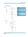
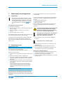
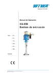
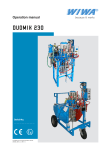
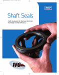
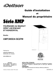
Machine description
Models:
Pos.
1
2
3
49. ...
78. ...
134. ...
269.13
269.27
4
5
6
7
8
269.36
521.14
521.19
680.14
9
10
11
Description
Muffler
Safety valve
Air inlet (connection for air maintenance unit, compressed air regulator or
compressed air stop valve)
Air motor
Distance bolt
Adjusting cup
High pressure head
Material outlet / Connection for nonreturn valve
Pressure relief plug / Connection for
drain valve
Material pump
Filling pipe
Fig. : 3.1
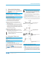
Models:
269.62
521.32
521.40
680.24
680.30
Fig.: 3.2
Translation of the original operation manual Extrusion Pump9
EXP_BAoDB • en • 04.12 • jw
Erection and Assembly
4
Erection and Assembly
4.1 Erection
Extrusion pumps can be integrated in plants
inside or outside of production rooms.
Dimensions of the equipment are indicated in
Chapter 9.1.
➤➤ In this connection take care that the compressed air
supply is interrupted, e. g. by means of a compressed
air stop valve.
An air maintenance unit or a compressed air regulator
can be connected directly to the pump.
➤➤ Connect a material hose or line to the material outlet of
the extrusion pump.
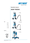
➤➤ optional version with high pressure filter (fig. 4.1):
➤➤ The machine is to be set up securely on a level and
solid surface. All operating elements must be easily
accessible. In order that the necessary volume of air
is guaranteed the compressor capacity must comply
with the amount of air needed by the machine and the
diameter of the air supply hoses must correspond to
the joints.
Depending on the pump version supplied, certain optional
accessories may have been unscrewed and packed in a
separate card-box, e. g.:
➤➤ Extrusion gun
➤➤ Air maintenance unit, or
➤➤ Compressed air regulator
➤➤ Please add these parts in accordance with the diagram of the machine enclosed in the user’s handbook
(chapter 3).
➤➤ When using accessories observe and adhere to the
respective operating instructions.
4.2 Assembly
Extrusion pumps are operating at high pressures.
➤➤ Check all parts that can be turned, nuts, screws and
hose couplings and tighten them to avoid material
from passing through these connections and causing
injuries.
➤➤ Check the permissible maximum air pressure for the
material hose and extrusion gun. It must be greater
than or equal to the maximum operational pressure for
the system, which is shown on the type plate on the
extrusion pump or on the machine card (chapter 10.3).
➤➤ Compare the maximum operating pressure of the
safety valve with the information on the machine card
(chapter 10.3) or the type plate. This information must
correspond.
➤➤ Prepare the plant where the extrusion pump shall be
integrated.
offers various rams and lifts for application with the extrusion pump. A
follow plate
or
follow cover can be attached to each device
(see Chapter 9.2).
Observe and adhere to the corresponding operating
instructions of these devices.
➤➤ Install the extrusion pump into the existing plant.
➤➤ Connect the extrusion pump to the compressed air
supply.
10
fig. 4.1
➤➤ Now fill Release agent into the adjusting cup.
The adjusting cup should be filled up to the half.
The Release agent is used for lubrication of the piston
and to avoid hardening of the upper packing.
We recommend to use
Release Agent, Order
No. 0163333.
➤➤ Fill the maintenance unit with pneumatic oil or antifreeze and take the setting as described in chapter 9.1
"Maintenance on the maintenance unit. (This does not
apply to machines delivered in a standard version with
only a compressed air regulator.)
Result
Now the machine is ready for operation. You can proceed
with first cleaning (Chapter 5).
Translation of the original operation manual Extrusion Pump
EXP_BAoDB • en • 04.12 • jw
Start-up
5
Start-up
5.1 Preparation
Job
You wish to erect the machine at the site and prepare it for
operation.
Prerequisite
The material to be worked is prepared.
All materials to be sprayed should be marked with information on viscosity, processing temperatures, mixing proportions etc. If this is not the case please acquire this data
from the relevant manufacturer.
offers a broad selection of accessories for the
optimum processing of coating materials, e.g.:
➤➤ Follow plate
➤➤ Follow cover
➤➤ Ram
➤➤ Lift
➤➤ Air maintenance unit or compressed air regulator
➤➤ Non-return valve
➤➤ Material hoses of various lengths and cross sections
➤➤ Extrusion gun
➤➤ Extrusion nozzles
➤➤ Collecting trays for condensed water
For further accessories and more details do not hesitate to
directly contact
or the
Customer Service.
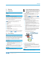
5.2 First cleaning
➤➤
➤➤
➤➤
➤➤
➤➤
If using a follow plate or follow cover pay attention to the notes mentioned in Chapter 9.2.
Furthermore, observe and adhere to the notes
of the operating instructions of the applied
rams / lifts.
Hold the material hose respectively extrusion gun (if
existing) into the empty container.
Slowly open the compressed air stop valve of the
equipment.
When using a
maintenance unit or a
compressed air control observe and adhere to the
notes mentioned in Chapter 9.1.
Pump solvent into the empty container until clean material is protruding.
optional version with high pressure filter:
➤➤ Remove the filter insert from the high pressure
filter in accordance with chapter 9.5.
➤➤ Hold the drain hose (Fig 5.1, Pos. 2) into empty
containe and secure it against slipping.
➤➤ Open the relief tap on the high pressure filter (Fig
5.1, Pos. 1).
➤➤ Open the main air supply tap. (Fig 5.1).
Adjust the air regulator to a maximum of 2 bar (30
psi) by slowly turning the regulating screw to the
right.
➤➤ Allow the Wash Thinner, soiled with the test-medium, to run out of the relief hose into the empty
open container for at least 10 seconds.
➤➤ Close the relief tap (Fig. 5.1, Pos. 1).
Recommended cleaning time:
max. 2 bar
mind. 10 Sekunden
Job
This machine was factory tested, after assembly, for perfect functioning with a test medium. However, the extrusion
pump and/or the entire system should first be flushed with
solvent before spray operation begins so that the material
to be sprayed is not affected by the test-medium.
Prerequisite
You will need:
➤➤ open pail (or barrel) with a cleaning agent that is
compatible with the material and that has been recommended by the manufacturer.
➤➤ empty, open pail to hold the rest material which is in the
extrusion pump.
The extrusion pump is properly installed in the plant, all
material and air connections are correctly established.
Procedure
➤➤ compressed air supply is shut-off.
➤➤ Move the extrusion pump into the solvent container.
fig. 5.1
➤➤ Switch off the compressed air supply.
➤➤ Open the drain valve for pressure relieve and let the
protruding material flow into the container with the
contaminated material.
➤➤ If you do not use an extrusion gun connect the material
hose to the device provided for this purpose or to the
equipment.
Result
The extrusion pump is ready for operation.
Translation of the original operation manual Extrusion Pump11
EXP_BAoDB • en • 04.12 • jw
Operation
6
Operation
6.1 Spraying/pumping material
Job
The material to be processed is to be applied to the surface to be coated.
Prerequisite
You will need:
➤➤ open pail (or barrel) containing the material to be
worked.
➤➤ empty, open pail to hold the rest material which is in the
extrusion pump.
The extrusion pump is properly installed in the plant, all
material and air connections are correctly established.
Procedure
➤➤ compressed air supply is shut-off.
➤➤ optional version with high pressure filter:
➤➤ Depressurize the system: Open the relief tap on the
high pressure filter.
➤➤ Place a filter element according to Chapter 8.3 into
the high-pressure filter.
➤➤ Move the extrusion pump into the material container.
If using a follow plate or follow cover pay attention to the notes mentioned in Chapter 9.2.
Furthermore, observe and adhere to the notes
of the operating instructions of the applied
rams / lifts.
➤➤ Hold the material hose respectively extrusion gun (if
existing) into the empty container.
➤➤ Slowly open the compressed air stop valve of the
equipment.
➤➤ When using a
maintenance unit or a
compressed air control observe and adhere to the
notes mentioned in Chapter 9.1.
➤➤ Supply the scoop piston pump with compressed air
again.
➤➤ Keep pumping into an empty collecting vessel, until
clear material starts to run out.
optional version with high pressure filter:
➤➤ Hold the drain hose into empty container and secure it against slipping.
➤➤ Open the drain valve on the high-pressure filter.
➤➤ Open the air tap lock.
➤➤ Turn the air pressure regulator control knob clockwise until the pump slowly cycles.
➤➤ As soon as coatings material comes out of the drain
hose, close the drain valve / drain screw tightly.
➤➤ Switch off the compressed air supply.
➤➤ Hold the extrusion gun over the surface to be coated.
➤➤ Supply the scoop piston pump with compressed air
again.
12
For that pay attention to the following:
Increase of the air pressure results in
➤➤ a higher material outlet pressure
➤➤ a higher material pumping capacity
➤➤ The maximum operating speed of the extrusion pump amounts to 30 double strokes per minute. (The slower
the operating speed the lower the wear)
➤➤ The required operating pressure is adjusted at the
compressed air regulator.
➤➤ When using a
air maintenance unit or a
compressed air regulator observe and adhere to the
notes mentioned in Chapter 9.1.
6.2 Interruption of work
➤➤ Interrupt the compressed air supply.
➤➤ When using an extrusion gun press the trigger for a
short
➤➤ while for pressure relieve.
6.3 Cleaning /Change of material
➤➤ Interrupt the compressed air supply.
When using an extrusion gun press the trigger for a
short while for pressure relieve.
Job
You wish to clean the extrusion pump before a longer
standstill or before a change of material.
Prerequisite
The solvent recommended by the material manufacturer is
available.
Procedure
➤➤ Interrupt the compressed air supply
➤➤ Carry out pressure relieve of the extrusion pump
➤➤ Slowly lift the extrusion pump from the material container
➤➤ Put the extrusion pump into the container filled with
solvent
➤➤ Apply compressed air to the extrusion pump. 2 bars
are sufficient.
➤➤ Put the material hose respectively the extrusion gun
into the empty waste bin until clean solvent agent
protrudes.
➤➤ Clean all accessories with the solvent recommended
by the material manufacturer. Observe and adhere to
the notes mentioned in the respective instructions.
➤➤ optional version with high pressure filter:
➤➤ Clean the filter insert or replace it if it is damaged.
➤➤ Place the cleaned or replacement filter insert into
the high-pressure filter according to Chapter 9.5.
Translation of the original operation manual Extrusion Pump
EXP_BAoDB • en • 04.12 • jw
Maintenance and inspection
7
Maintenance and inspection
7.1 Inspection
According to the rules for the prevention of accidents "Working with liquid jet systems" ("Arbeiten
mit Flüssigkeitsstrahlern", BGR 500, chap. 2.36)
the equipment must be checked and overhauled
at regular intervals by a specialist (
Service).
The equipment must be checked:
➤➤ before the first start-up,
➤➤ after changes and repairs of equipment parts having an
effect on safety,
➤➤ after an interruption of operation of more than 6
months,
➤➤ however at least every 12 months.
For equipment, which has been taken out of operation, the
check can be postponed up to the next start-up.
The results of the checks must be recorded in writing and
kept until the next check. The checking certificate or a
copy of it must be available at the place where the equipment is used.
7.2 Maintenance plan
Release agent control
Before each start-up check the level of the Release agent
and, if necessary, refill release agent.
The adjusting cup should be filled up to the half.
Please proceed as follows:
➤➤ Once the piston has reached top position, switch off the
unit.
➤➤ Relieve the pressure from the complete unit.
➤➤ Use a wire as dipstick and insert it carefully in a release
agent filler opening in the adjustment cup to check the
filling level.
➤➤ If the adjustment cup holds less than the specified minimum quantity, you must fill in release agent through the
filler opening.
The filling quantity depends on the corresponding
pump size. With a maximum filling level the release
agent will be visible at the bottom edge of the filler
openings.
Undesired material leaks on the piston can thus lead to
pump damage.
In order to prevent this from happening we recommend to
check and, if necessary, readjust the packing at regular
intervals:
➤➤ during initial commissioning.
➤➤ after the first 2 work days.
➤➤ later 1 x per week.
Exact intervals must be matched to the prevailing conditions of the application and should be determined as
necessary.
In order to prevent dangerous physical injuries
caused by escaping material and crushing
of limbs you should only replace the packing
with the unit completely depressurized.
The higher the running speed of the pump and
the abrasive properties of the material, the
higher the re-adjustment frequency.
➤➤ For this purpose switch off the unit and relieve the
pressure.
The pump must be downward stroke.
➤➤ Insert the attached stud driver into a free bore in the
adjustment cup.
➤➤ Turn the adjustment cup anti-clockwise to loosen.
➤➤ Turn the adjustment cup clockwise, until slight resistance can be felt. Then turn 1/4 of a turn further.
Replace the complete packing if:
➤➤ release agent comes out through the packing (can be
noticed by a permanent loss of release agent).
➤➤ the packing can no longer be adjusted.
➤➤ there is no clearance between adjustment cup and high
pressure head.
Readjusting the top packing
The prevailing local operating conditions for the pump
(operating time, running speed of the pump as well as the
abrasive properties of the material) will cause wear to the
top packing in the high pressure head of the material pump
(chapter 3).
Translation of the original operation manual Extrusion Pump13
EXP_BAoDB • en • 04.12 • jw
Disturbances during operation and trouble-shooting
8
Disturbances during operation and trouble-shooting
Disturbance
Trouble-shooting
Extrusion pump does not start despite
having triggered extrusion gun or
opened material outlet
1) Air stop valve is closed
2) Material outlet is clogged
3) Defective air motor
1) Open the air stop valve
2) Clean the material outlet
3) • Repair the air motor
• Replace the air motor
This work has to be carried out
by trained personnel only. Pay
attention to the respective spare
parts lists.
Extrusion pump is working regularly,
however the required pressure is not
reached
1) Air pressure too low
2) Material outlet too big
3) Nozzle too big when using an
extrusion gun
1) • Increase the air pressure
• Check the air lines for correct
cross sections
2) Reduce material outlet
3) Insert a smaller nozzle
Extrusion pump is working irregularly,
does not reach the required pressure,
does not stop even with closed extrusion gun or closed material outlet
1) Viscosity of the material to be
worked is too high
2) Leaky valves and packings
1) • Increase the operating pressure
of the ram
• Use a bigger extrusion pump
• Eventually heat the material to be
worked
2) Replace wear parts
14
Possible cause
Translation of the original operation manual Extrusion Pump
EXP_BAoDB • en • 04.12 • jw
Various brief instructions
9
Various brief instructions
Procedure
The scoop piston pump including accessories must be switched off and depressurized
before assembly / disassembly. Please follow
the safety notes in chapter 2.
9.1 Maintenance unit / compressed air
regulator
Regulating the compressed air supply
Increase the air pressure: Turn spindle clockwise
Reduce the air pressure:
Turn spindle anti-clockwise
Only for maintenance unit:
Lubricant or anti-freeze agent
➤➤ Also check and, if necessary, top up the lubricant for
the fan motor in the container of the service unit.
➤➤ High humidity can cause icing of the motor.
➤➤ In case of icing use pure anti-freeze agent.
➤➤ Attach the follow plate (Fig. 9.2.3 and 9.2.4) respectively the follow cover (Fig. 9.2.1 and 9.2.2) to the ram
or directly to the extrusion pump.
➤➤ Observe and adhere to the notes mentioned in Chapter
9.4.
➤➤ Connect the air hose of the ram to the hose spout (Fig.
9.2.1 to 9.2.4, Item 1) on the follow plate / follow cover.
Adjusting the fog oiler on the maintenance unit
➤➤ Allow the air motor to run slowly with an air inlet pressure of approx. 4 bar.
➤➤ In the inspection glass of the fog oiler check whether
one drop of lubricant is released into the compressed
air with every 10 to 15 double strokes of the air motor.
Should this not be the case, adjust the regulating screw
on the lubricator accordingly.
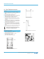
fig. 9.2.1 Follow cover,
large (200 ltr tank)
Draining the condensation water
➤➤ Before each use and, in case of high humidity, also
during operation, drain of the accumulated condensation water through the drain valve.
fig. 9.2.2 Follow cover,
small (20-60 ltr tank)
Only use the lubricants and anti-freeze agents
listed in the chapter 10.1.
fig. 9.2.3 Follow plate, large
(200 ltr tank)
9.2 Follow plate / Follow cover
Problem definition
Fitting a scoop piston pump with a follow plate / follow
cover.
Prerequisite
The following is required:
➤➤ 1 follow plate or follow cover
➤➤ 1 mounting kit for follow plate / follow cover
The use of a follow plate / follow cover is highly application
specific. The mounting kits must be ordered in compliance
with the accessories used.
Please consult the
customer service or directly
the
company to ask for the right selection and
order number for follow plate / follow cover and mounting
kits.
fig. 9.2.4 Follow plate, small
(20-60 ltr tank)
for immersion into the material container
➤➤ Loosen the locking toggle (Fig. 9.2.1 to 9.2.4, Item 2)
from the ventilating housing of the follow plate / follow
cover.
➤➤ Insert the follow plate / follow cover into the container
together with the extrusion pump. When doing this, the
air in the material container / barrel is released through
the opening. Adhere to the notes mentioned in Chapter
9.4.
Translation of the original operation manual Extrusion Pump
EXP_BAoDB • en • 04.12 • jw
15
Various brief instructions
➤➤ Screw the locking toggle (Fig. 9.2.1 to 9.2.4, Item 2)
back into the ventilating housing of the follow plate /
follow cover as soon as material protrudes from the
opening.
container / barrel exchange
Proceed as follows to move the extrusion pump out of an
empty container:
➤➤ Make sure that the air hose has been properly connected to the hose spout (Fig. 9.2.1 to 9.2.4, Item 1) on
the follow plate / follow cover.
➤➤ Open the ball valve on the ram (Chapter 8.3) and set
the lever on the ram to "UP". Compressed air is blown
into the empty container / barrel lifting the extrusion
pump with the follow plate / follow cover off the container / barrel.
➤➤ Shut the ball valve on the ram (Chapter 8.3).
➤➤ Exchange the container / barrel.
Always switch off the unit before starting maintenance and repair work.
Danger of burning!
Depending on the temperature setting, the temperatures on the outside of the follow plate and
on the drum may reach max. 80 °C. You should
therefore always wear protective gloves.
Any contact with solvents or water can cause
damage to the unit.
Do not use any solvent containing materials for
cleaning and do not direct high pressure or water
jets directly towards the unit.
cleaning
➤➤ If required clean the outside of the follow plate / follow
cover.
Special notes for electrically heated follow plates
Please comply with the following instructions:
By using an electrically heated follow plate
materials with high viscosity can be maintained
flowable or heated up. Heating is accomplished
by a special heating element mounted inside
the follow plate. The temperature can be set by
means of a thermostat (optionally available). The
electrically heated follow plate is suitable for
216.5 l drums.
The unit must not be operated in explosion endangered environments.
Heating solvent containing and easily inflammable
materials can lead to explosion and thus cause
severe injury to persons and material damage.
Please follow the processing instructions in the
data sheet provided by the material manufacturer
- especially the information concerning application
temperature (ignition temperature) of the material.
Always make sure that the temperature of the
material to be processed is lower than the ignition
temperature specified by the manufacturer.
The electric connection must only be made by
expert personnel with profound knowledge about
electrical engineering.
Take note of the connected loads.
The connection must only be made with the unit
switched off.
16
Translation of the original operation manual Extrusion Pump
EXP_BAoDB • en • 04.12 • jw
Various brief instructions
eltherm
TEL.: +49(0)2736/ 4413-0
FAX.: +49(0)2736/ 4413-50
e-mail: [email protected]
www.eltherm.de
Elektrowärmetechnik GmbH
Ernst- Heinkel-Straße 8-10
9.3 Version 57299
with thermostat
(optional)
Burbach
Electronic Temperature Controller Type ELTC/1-4/05
for wall mounting; 1 contactor
Description:
The electronic temperature controller type
ELTC/ is designed for use as an ambient
thermostat or surface thermostat with remote
sensor. Cable glands and terminations are
provided for the power connection.
The unit is supplied in a weather proof
polycarbonate casing for wall mounting, with a
transparent (ELTC/05 = grey) cover. The
controller should be protected from direct
sunlight when used outdoors.
Function:
If the sensed temperature is lower than the
adjusted set point, the relay contact closes and
the heating switches on. The yellow LED
glows while the contact is closed.
During sensor discontinuity or sensor
short circuit, the heating is switched off!
Installation
as
outside
temperature
controller:
The sensor cable is to be shortened so that
the sensor cover can be secured inside of the
M12 cable gland. There should be 15mm of
the sensor cover exposed after securing the
sensor into the gland.
Suggested setting for frost protection: +3°C
Technical Data:
Supply voltage:
switching capacity
measuring input
adjustment ranges:
ELTC/05
ELTC/1
ELTC/2
ELTC/3
ELTC/4
ambient temperature
control characteristic
output
LED (yellow)
material of case
dimension
protection type
weight
cable glands:
230V, +/- 10%, 50Hz,
if not otherwise stated
16A
PT100 DIN 2- wire
+3°C
-5...+15°C
0...+100°C
0...+250°C
+150…+400°C
-30...+60°C
two-limits controller
1 relay contacts
HEATING ON
Polycarbonate
130x130x75mm
IP 66
520g
for connection of self- 1x M12; 2x M25
regulating heating tape:
xxx
for connection from both 1xM25;1xM12
ends of a resistance 2xM20
cable:
if voltage specification is
different from 230V
Translation of the original operation manual Extrusion Pump17
EXP_BAoDB • en • 04.12 • jw
BU-010_eng.DOC
Revision: 1
Seite 1 von 1
Various brief instructions
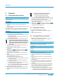
9.4 Ram / Single post ram press
detail
Operation
➤➤ Check if all accessories are correctly connected.
➤➤ Set the compressed air control (Fig. 9.4.4 Item 3) on 2
bars.
➤➤ Set the lever (Fig. 9.4.4, Item 1) on "UP".
➤➤ The extrusion pump is slowly lifted.
➤➤ Place the material container / barrel on the ram base.
➤➤ Set the lever (Fig. 9.4.4, Item 1) on "DOWN".
The extrusion pump is slowly lowered.
➤➤ Pay attention that the container is placed in such a
way that the sequence plate can be moved into the
container.
➤➤ Screw the locking toggle (Fig. 9.2.1 + 9.2.2, Item 2
and Fig. 8.2.3 + 8.2.4, Item 2) off the sequence plate /
sequence cover to let the air go out.
➤➤ Screw the locking toggle (Fig. 9.2.1 + 9.2.2, Item 2
and Fig. 8.2.3 + 8.2.4, Item 2) back into the sequence
plate / sequence cover as soon as the material protrudes.
➤➤ Set the pressure on the requested operating pressure
at the compressed air control (Fig. 9.4.4, Item 3).
fig. 9.4.2 ram press (0.3 t)
detail
Switch off the compressed air supply when
interrupting or stopping operation.
Exchange of the container
➤➤ Open the ball tap (Fig. 9.4.4, Item 2).
➤➤ Set the compressed air on 2 bars at the compressed
air control (Fig. 8.3.4, Item 3).
➤➤ Set the lever (Fig. 9.4.4, Item 1) on "UP".
The extrusion pump is lifted.
➤➤ Take off the container to the bottom.
fig. 9.4.3 Single post ram press (0.375 t)
detail
fig. 9.4.4 detail
fig. 9.4.1 Ram with follow plate (0.3-0.7 t)
18
Translation of the original operation manual Extrusion Pump
EXP_BAoDB • en • 04.12 • jw
Various brief instructions
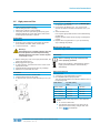
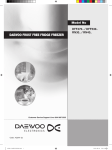
9.5 High pressure filter
Job
➤➤
1.
2.
3.
Clean or replace the filter insert:
after shutting down the unit (daily).
before every change of spray material.
if the pump does not cycle although the spray gun is
triggered (without tip) or the drain valve / drain screw
for the high-pressure filter is opened.
Prerequisite
Required are:
➤➤ An empty, open container for the mixture of solvent /
spray material, hereafter called container "B".
➤➤ 1 open-end wrench Size 13
Warning!
If blockages occur, residual pressure may still
be in the system even after depressurizing.
Residual pressure can lead to serious injuries
to the body or eyes.
➤➤ Before starting any work on the high-pressure filter, the
pump must be turned off.
➤➤ Briefly trigger the spray gun.
➤➤ To drain pressure, open the drain valve / screw on the
high-pressure filter.
➤➤ Disassemble the high-pressure filter very carefully!
➤➤ Replace worn parts with new ones..
Removing the filter insert
➤➤ Unscrew the cap ��������������������������������������
(Picture 9.5.1, pos. 1)���������������
with the spanner (Picture 9.5.1, pos. 2).
➤➤ Unscrew the nut (Picture 9.5.1, pos. 3) with a fork
wrench and remove the filter insert (Picture 9.5.1, pos.
4)).
➤➤ Clean the filter insert.
Use only the appropriate solvent for the material being
worked with.
Replace the filter insert should any sign of damage be
present..
➤➤ Replace the o-ring (Picture 9.5.1, pos. 5) should any
sign of leakage be present
Mounting the filter insert
➤➤ Mount the high pressure filter in reserve order.
Instructions
Before restarting the pump ensure that the
unit is properly grounded.
R (corrosion resistant) + RS (stainless) versions:
Lightly grease all threads to ease assembly /
disassembly.
Filter insert selection
Procedure
➤➤ Hold the drain hose into container "B".
➤➤ Close the air tap lock for the pump.
➤➤ To depressurize, open the drain valve (Fig.e 9.5.1, pos.
6).
The insert must:
➤➤ correspond to the material being sprayed
➤➤ be compatible with the spray tip used
The mesh should always be a little finer that the bore of
the tip being used:
Filter insert
Tip size (mm/")
fromto
M200 (white)
-
0,23/.009
M150 (red)
0,23/.009
0,33/.013
M100 (black)
0,33/.013
0,38/.015
M70 (yellow)
0,38/.015
0,66/.026
M50 (orange)
0,66/.026
-
If working with heavily pigmented or fiber-filled materials:
➤➤ do not use a filter insert.
➤➤ the standard suction sieve may need to be replaced with a sieve having a larger mesh size.
➤➤ use a
reversible tip
fig. 9.5.1
Translation of the original operation manual Extrusion Pump19
EXP_BAoDB • en • 04.12 • jw
Appendix
10 Appendix
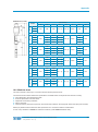
10.1 Technical Data and Order References
Model
Ø Air
Motor
MP 680
MP 521
MP 269
MP 134
MP 78
MP 49
(mm)
PressureRatio
Output
at 20 cycles per
min.
(l/min)
per cycle
Max.
Input Air
Pressure
Max.
Operating
Pressure
(cm3)
(bar)
(bar)
49
8
Version* / Order Number
N
R
128
0642739
---
200
0642735
---
360
0642734
---
8
128
0640831
0640832
8
200
0640833
0640834
49.16
85
16 : 1
49.25
105
25 : 1
49.45
140
45 : 1
78.16
85
16 : 1
78.25
105
25 : 1
78.45
140
45 : 1
8
360
0640835
0640836
78.94
200
94 : 1
5
470
0640837
0640838
134.15
105
15 : 1
8
120
0640839
0640840
134.27
140
27 : 1
8
216
0640841
0640842
134.54
200
54 : 1
8
432
0640843
0640844
134.73
230
73 : 1
6,5
474,5
0640845
0640846
269.13
140
13 : 1
8
104
0640847
0640848
269.27
200
27 : 1
8
216
0640849
0640850
269.36
230
36 : 1
8
288
0640851
0640852
269.62
300
62 : 1
6,5
403
0640853
0640854
521.14
200
14 : 1
112
0641680
---
521.19
230
19 : 1
152
0642320
---
521.32
300
32 : 1
256
0642321
---
521.40
333
40 : 1
320
0642322
---
680.14
230
14 : 1
13,6
680
8
112
0641708
0642455
680.24
300
24 : 1
13,6
680
8
192
0642323
0642752
680.30
333
30 : 1
13,6
680
8
240
0642324
0642753
0,9
1,5
78
2,6
134
5,2
269
10,4
521
For all systems the sound pressure level is below 80 db(A)
8
Machinery materials
Release agent*
Best.-Nr. 0163333
Pneumatic oil (0.5 liter)**
Best.-Nr. 0632579
Anti-freezing agent**
Best.-Nr. 0631387
Securing material (50 ml)***
Best.-Nr. 000015
Lubricant (acid-free grease)***
Best.-Nr. 000025
20
*
Plasticizer to fill into the release agent cup of the material
pump
** for service unit
*** Materials required for cleaning and repair work (see information in spare parts lists)
Translation of the original operation manual Extrusion Pump
EXP_BAoDB • en • 04.12 • jw
Appendix
Dimensions (in mm)
Dimensions
A
B
C
D
E
F
G
H
642
385
1027
G ½" (I)
G ¾" (I)
Ø 70
234
389
49.16
49.25
49.45
78.16
430
1111
G ½" (I)
289
78.25
430
1111
G ½" (I)
289
430
1111
G ½" (I)
78.94
559
1240
G 1" (I)
358
134.15
430
1111
G ½" (I)
289
430
1111
G ½" (I)
559
1240
G 1" (I)
559
1240
G 1" (I)
681
G ¾" (I)
Ø 70
289
134.27
269.13
430
1111
G ½" (I)
289
269.27
579
1260
G 1" (I)
358
579
1260
G 1" (I)
269.62
651
1332
G 1" (I)
521.14
579
1260
579
1260
651
1332
651
1332
MP 680
MP 521
MP 134
78.45
MP 269
MP 78
MP 49
Model
134.54
681
134.73
269.36
521.19
521.32
681
681
521.40
680.14
680.24
680.30
681
579
1260
651
1332
651
1332
G ¾" (I)
Ø 70
289
358
433
433
358
G ¾" (I)
Ø 80
358
457
370
358
G 1" (I)
G 1" (I)
Ø 80
358
370
463
370
G 1" (I)
G 1" (I)
Ø 80
358
370
463
370
10.2 Machine chart
This user’s manual is valid only in connection with the following machine chart:
The machine chart includes all machine specifications and details which are important and relevant for safety:
➤➤ exact designation and manufacturing data
➤➤ technical specification and limit values
➤➤ equipment and checking certificate
➤➤ data for purchase
➤➤ machine features (machine components and accessories included in the supply with article and spare parts number)
Please pay attention that the machine chart specification is in accordance with the machine label.
In case of any deviations or default of a label we would ask you to advise us without delay.
Translation of the original operation manual Extrusion Pump21
EXP_BAoDB • en • 04.12 • jw