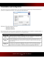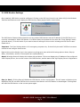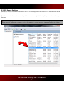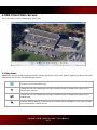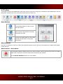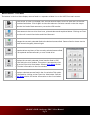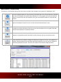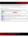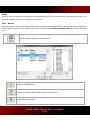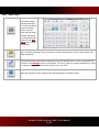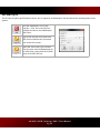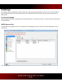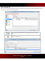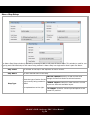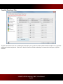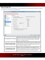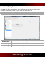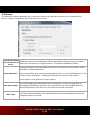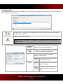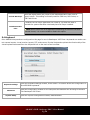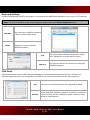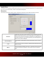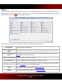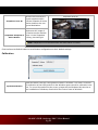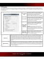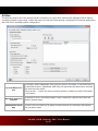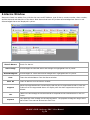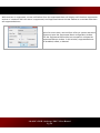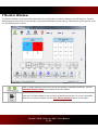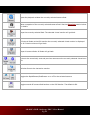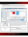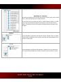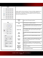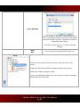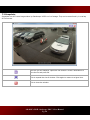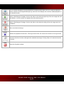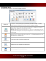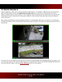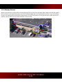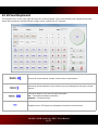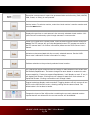
1
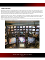
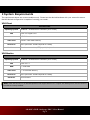
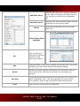
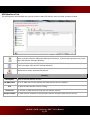
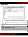
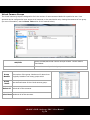
Table of Contents
1 INTRODUCTION
1
2 SYSTEM REQUIREMENTS
2
3 INSTALLATION AND CONFIGURATION
3
3.1 VDS MONITOR SETTINGS
3.2 VDS SERVER SETTINGS
4
5
4 VDS CLIENT MAIN SCREEN
6
4.1 MAP ICONS
4.2 TOOLBAR
Maps Buttons
Watch Buttons
Watch Buttons - Alarm Button
Watch Buttons - Live Menu
Watch Buttons - Playback Menu
Watch Buttons - Monitor Button
Cameras
Tools
Tools - Macros
Tools - Other Tools
Exit and Log Off
5 SETTINGS
6
7
7
7
7
8
9
10
10
11
11
12
13
14
5.1 SERVER SETTINGS
VIGIL Servers Tab
VDS Monitors Tab
VGA Monitor Groups Tab
Virtual Camera Groups
Macro Settings Tab
Macro Step Setup
Joystick Functions Tab
Display Settings Tab
14
14
16
17
18
19
20
21
22
SITE MAP SETTINGS
24
Users Tab
VDS Registration Tab
Import/Export Settings Tab
5.2 ALARMS
5.3 DESTINATIONS
5.4 KEYBOARD
Keyboard Settings
COM Ports
Joystick Setup
Parameters
Buttons
25
26
27
28
29
30
31
31
32
32
33
3xLOGIC's VIGIL Gatekeeper VDS 7.1 User Manual
Pg. i
Calibration
5.5 PLAYBACK
5.6 MISC
35
36
37
6 ALARMS WINDOW
38
7 MONITOR WINDOW
40
7.1 EXPANDED MONITOR MENU
7.2 SNAPSHOTS
42
46
8 LIVE VIEWER WINDOW
47
9 PLAYBACK WINDOW
49
9.1 PLAYBACK SEARCH
52
10 VDS MONITOR SCREEN
53
11 ALARM MONITORS
55
11.1 SITEMAP ALARMS
56
12 VIRTUAL KEYBOARD
57
13 SITE MAP DESIGNER
60
13.1 SITE MAP DESIGNER ICONS AND BUTTONS
13.2 SITE MAP / HOT SPOT PROPERTIES
62
63
14 LANGUAGE SWITCHER
65
15 CONTACT INFORMATION
66
3xLOGIC's VIGIL Gatekeeper VDS 7.1 User Manual
Pg. ii
1 Introduction
Gatekeeper VDS gives you unrivalled access to live and recorded video from any of your networked VIGIL Servers. Advanced playback and coordinated display allows you to identify and review events of interest quickly and easily.
The result is an accurate and efficient investigation of incidents with easy export of evidence material.The Sitemap
feature provides unlimited map layers and camera links for easy access to your cameras.
A unique combination of control, efficiency, and adaptability offers investigators unparalleled accessibility and manageability for their video network. The result is rapid response times, reduced investigator times, and increased
access and effectiveness of your video surveillance investments.
Disclaimer: *This application has been optimized for use with Windows XP and Windows 7. 3xLOGIC does not actively support other operating systems. Installing this application on operating systems
other than the those mentioned above may have undesirable consequences.
3xLOGIC's VIGIL Gatekeeper VDS 7.1 User Manual
Pg. 1
2 System Requirements
The requirements below are recommendations only. Please test the desired hardware with your network to assure
that the desired configuration is capable of meeting your needs.
VDS Client
Recommended
Operating System
Windows 7 Professional or Ultimate (32 or 64 bit)
CPU
Intel i3 or higher CPU
RAM
2GB RAM
Video Card
512MB – 1GB Video Memory
Hard Drive
SATA (Minimum 100MB required for install)
Hardware
Touch screen monitor, PTZ joystick/keyboard
VDS Monitor
Recommended
Operating System
Windows 7 Professional or Ultimate (32 or 64 bit)
CPU
Intel i5 or i7
RAM
2 – 4GB RAM
Video Card
2 – 4 GB Video Memory
Hard Drive
SATA (Minimum 100MB required for install)
Hardware
VGA monitors
Note: VIGIL VDS will only run on Windows platforms that support DirectX 7.01 or higher. Run DxDiag.exe to view the version of
DirectX that is currently installed.
3xLOGIC's VIGIL Gatekeeper VDS 7.1 User Manual
Pg. 2
3 Installation and Configuration
After double clicking on the installation EXE file, the component selection screen will open. Select the desired components to be installed and click Next. The components are discussed below.
Gatekeeper VDS is split into three components:
l Gatekeeper VDS Client
l Gatekeeper VDS Monitor
l Gatekeeper VDS Service
Each component fulfills a distinct purpose, detailed below. Each component can be installed on a separate system. It
is recommended that each component is installed on its own separate system.
Details
Gatekeeper VDS Contains the main user interface of Gatekeeper VDS. User configuration of Gatekeeper VDS
Client
Monitor takes place here, along with the majority of user interaction.
Connects to Gatekeeper VDS Service to display camera feeds on configured monitors. It is
Gatekeeper VDS
recommended that Gatekeeper VDS Monitor be installed on a different machine than GateMonitor
keeper VDS Client.
The essential core component of Gatekeeper VDS. Both VDS Monitor and VDS Client con-
Gatekeeper VDS
nect to and communicate with the Gatekeeper VDS Service. It is recommended that GateService
keeper VDS Service be installed on a different machine than Gatekeeper VDS Client.
3xLOGIC's VIGIL Gatekeeper VDS 7.1 User Manual
Pg. 3
3.1 VDS Monitor Settings
Once installed, VDS Monitor must be configured. Clicking on the VDS icon(circled in red, below-left,)in the Windows
Task Bar Notification area will deploy the VDS Monitor status popup window, shown below.
The VDS Monitor Status window shows the current mode of VDS Monitor and the IP address of the VDS Service it is
currently connected to. When VDS Monitor is in Offline Mode, this window will also have the “Clear Settings” button
(pictured above). Click this button if you want to clear all settings for this monitor including the VDS Service associated with it.
Important: The Clear Settings button is for emergency purposes only. It should only be used if VDS Service cannot
connect to and configure that monitor.
Right-clicking on the Monitor icon in the system tray brings up a menu with the following options: About, Stop (or
Start), Information, and Exit. These options are explained below.
About: Selecting About will display the window pictured below. This screen displays the IP address of the configured
VIGIL Display Server, the current version of the VDS Monitor, and the state of the Vigil Display Server’s Registration.
Stop (or Start): Clicking Stop will disable the VDS Monitor on the current system. This will cause no Monitors to be
displayed, and will not allow VDS Service to connect to the Monitor until VDS Monitor is started again. Clicking Start
will start the VDS Monitor on the current system again.
3xLOGIC's VIGIL Gatekeeper VDS 7.1 User Manual
Pg. 4
3.2 VDS Server Settings
VDS Server requires no user involvement—it will run in the background of the machine it is installed on. It can be
viewed in the windows Services list.
The Windows service list can be accessed by clicking on Start >> right-click on My Computer and select Manage >>
Services.
Caution: Changing the Windows Service settings can cause VDS Server to stop functioning. Do not change these
settings unless it is absolutely necessary and you are absolutely certain how your changes will affect the system.
3xLOGIC's VIGIL Gatekeeper VDS 7.1 User Manual
Pg. 5
4 VDS Client Main Screen
This is the main screen of Gatekeeper VDS Client.
4.1 Map Icons
Gatekeeper VDS can create maps that contain camera layouts for entire sites. Details regarding creation of the sitemap can be found in the Site Map Designer section.
This icon is a link to another map.
Clicking this icon will change the currently selected monitor to display the output from a
pan-tilt-zoom camera.
Clicking this icon will change the currently selected monitor to display the output from a
fixed camera.
A camera with an asterisk in the corner is a camera that is available for Live View only and
is not connected to a VIGIL Server.
3xLOGIC's VIGIL Gatekeeper VDS 7.1 User Manual
Pg. 6
4.2 Toolbar
The toolbar found on the Gatekeeper VDS main screen is where the majority of interaction with Gatekeeper VDS will
take place. What follows is an overview of the function of each icon.
Maps Buttons
Click the Back button to return to the
last map viewed.
Opens the site-map selection window,
picturedon the right.
Click the Forward button to view a map
that was viewed before clicking the
Back button.
Watch Buttons
Use the Live buttons to view live video of an available camera input. A group of sub buttons will appear that enable
further actions.
Watch Buttons - Alarm Button
Click the Alarm button to deploy the Server Alarm window. Alarms are sent by the Server to Gatekeeper VDS. The Alarms Icon will flash when new alarms are present.
See the Alarms Window section for more details.
3xLOGIC's VIGIL Gatekeeper VDS 7.1 User Manual
Pg. 7
Watch Buttons - Live Menu
The buttons in the Live Menu display camera feeds in a separate window live on the VDS Client main screen.
Allows a user to view live footage from various camera feeds. Click it to open the Live sub buttons described below. Click it again to close the submenu. Select a camera on the site map to
open the live feed of that camera on your active VDS monitor.
Allows access to the two Live View icons, pictured above and explained below. Clicking on Client
Live View will reveal View Active and View Camera #.
Changes the currently selected feed to the desired camera feed. Camera feed is chosen via the
virtual numeric keypad, pictured right.
Snapshot allows a picture of the currently selected camera feed
to be captured and stored locally or on a virtual drive.
Displays the currently selected virtual monitor feed in VDS
Client within the Live window. This option is accessed by clicking on the Client Live View button. See the Live View section
for further information on the Live window.
Displays a desired camera feed in the Live window.This option
is accessed by clicking on the Client Live View button. See the
Live View section for further information on the Live window.
3xLOGIC's VIGIL Gatekeeper VDS 7.1 User Manual
Pg. 8
Watch Buttons - Playback Menu
The buttons in the Playback Menu allow previously recorded video footage to be replayed in Gatekeeper VDS.
Use the Playback button to view previously recorded video from various cameras. Playback
will open the Playback sub buttons described below. Clicking again will close the submenu.
Select a camera from the site map and it will open the Playback window for that selected
camera.
Opens the Playback window for the currently selected camera/matrix input.
Prompts for the desired camera feed to be input via the digital numeric keypad. Selected
feed will be displayed in a separate window.
Displays in a separate window the feed currently playing in the user-selected monitor.
Allows searches to be made of footage recorded from a specific monitor. All footage from
multiple camera feeds can be searched and stitched together into one piece of footage for
effective playback and export. See below for details on the Monitor Output window.
3xLOGIC's VIGIL Gatekeeper VDS 7.1 User Manual
Pg. 9
Selecting a monitor and pressing Search will present all of the footage segments that have been recorded in the
selected virtual monitor for the allotted time. Individual sections of playback can be double-clicked and viewed. Additionally, clicking View Stitched Cameras will play back all of the footage from the selected virtual monitor in a single
stitched-together recording. This recording can then be saved, exported, or played back at will.
The purpose of this feature is to allow a user to track a target’s progress across a range of several camera fields.
Watch Buttons - Monitor Button
The monitor button launches the monitor window. This window is used for a variety of purposes all revolving around
manipulating the monitor’s display. The monitor window is discussed below at length.
Opens the monitor window. See the Monitor Window section for details.
Cameras
These buttons allow the cycling of camera feeds on the currently selected virtual monitor.
Displays the previous camera in the currently selected virtual monitor. Multiple clicks will continuously cycle through cameras in reverse order.
Displays the next camera in the currently selected virtual monitor. Multiple clicks will continuously
cycle through camera feeds.
3xLOGIC's VIGIL Gatekeeper VDS 7.1 User Manual
Pg. 10
Tools
The tools icon set contains the miscellanea of the Gatekeeper VDS main screen buttons. These buttons do not fit into
any other category and serve a wide range of purposes.
Tools - Macros
Macros are sets of user-defined actions that can be recorded and executed at a later date by Gatekeeper VDS Client.
To learn about how to set up or modify Macros, see the section named Macro Settings Tab under “Server Settings”
(5.1).
Opens the Macro Window (pictured below.)
Runs the selected Macro.
Displays or hides the Macro Steps portion of the window.
Closes the Macro window.
3xLOGIC's VIGIL Gatekeeper VDS 7.1 User Manual
Pg. 11
Tools - Other Tools
Launches a virtual
keyboard interface.
The virtual keyboard
is used to change
monitor layouts,
select camera feeds,
and take snapshots
of selected cameras.
Please see the Keyboard section for further details.
Opens a window showing a list of directories on the local machine to view saved videos and
image snapshots.
Launches an external application configured from the settings menu. Further information can
be found in the Settings section of this guide. The icon’s name will change depending on what
it is named. The original state of the icon will say “ext. EXE”.
Opens the settings window. Settings are discussed below in greater detail.
3xLOGIC's VIGIL Gatekeeper VDS 7.1 User Manual
Pg. 12
Exit and Log Off
The Exit and Log On/Log Off buttons control who is signed in to Gatekeeper VDS and allows the shutting down of the
system.
Exits the Gatekeeper VDS Client
program. Click Yes in the Exit Confirmation window to exit Gatekeeper
VDS Client. Logs off the current VDS Client user.
VDS client’s interface will close and
open to the title screen.
Opens the VDS Client Login window.
Enter the user name and password for
the VDS Client, along with the IP/DNS
name of the VDS Service.
3xLOGIC's VIGIL Gatekeeper VDS 7.1 User Manual
Pg. 13
5 Settings
The settings window of Gatekeeper VDS is where all of the setup and configuration is done. This is the first window
that must be interacted with once Gatekeeper VDS is installed and launched. Each tab and sub tab is discussed in
detail below.
5.1 Server Settings
When launched, the Server Settings tab is selected by default in the Settings window. Its many functions and tabs are
explained below.
VIGIL Servers Tab
The VIGIL Servers tab deals with the configuration and management of the VIGIL Servers that Gatekeeper VDS is
monitoring.
Cont'd on next page.
3xLOGIC's VIGIL Gatekeeper VDS 7.1 User Manual
Pg. 14
Add VIGIL Server
Opens the Add VIGIL Server window, pictured to
the left. Enter the required information and click
OK to configure a VIGIL Server to Gatekeeper
VDS.
Edit VIGIL Server
Opens the VIGIL Server settings window, allowing
manipulation of VIGIL Server values.
Delete
Deletes the selected VIGIL Server from Gatekeeper VDS.
Opens the Virtual Switch Input Mappings window.
Virtual Switch Input
Mappings
Add
Opens a window (pictured right) to manually
configure a Virtual
Switch input mapping.
Virtual Switch Input Mappings window
Edit
Delete
Auto Map
Print
Change the details of a previously mapped virtual switch input. The window
is identical to the “Edit Virtual Switch Input Mapping” window.
Deletes the currently selected virtual switch input. Deleting an input will
remove its feed from VDS Monitor and render its input number dysfunctional.
Automatically detects and configures all cameras on all VIGIL Servers configured in Gatekeeper VDS. It will group cameras from a given VIGIL
Server together, as can be seen in the picture above and to the left.
Prints a list of all virtual switch input mappings.
3xLOGIC's VIGIL Gatekeeper VDS 7.1 User Manual
Pg. 15
VDS Monitors Tab
The VDS Monitors tab manages the physical monitors that VDS Monitor uses to display its camera feeds.
Opens a window used for adding and editing VDS Monitors, pictured and explained on the next
page (VDS Monitor Settings Window).
Opens the VDS Monitor Settings for the currently selected VDS Monitor, pictured and explained
on the next page (VDS Monitor Settings Window).
Deletes the currently selected VDS Monitor.
Columns:
Description
IP/DNS Name
Port
VGA Count
Assigned VGA #
Name of the VDS Monitor service.
The IP or DNS name of the system with VDS Monitor service installed.
The port the VDS Monitor service is using.
The number of VGA monitors using the VDS Monitor service.
The VGA monitor numbers for the monitors that are using the VDS Monitor service.
3xLOGIC's VIGIL Gatekeeper VDS 7.1 User Manual
Pg. 16
VGA Monitor Groups Tab
The VGA Monitor Groups tab is used for creating, editing, and deleting VGA Monitor Groups. VGA Monitor Groups can
be used to control which VDS Monitor Systems a user has access to (see Users Tab section below), or to display
server alarms for VIGIL Servers VDS Service is configured to check for alarms (see VIGIL Servers Tab section
above).
Clicking add opens the VGA Monitor Groups Setup window for configuration of a VGA monitor
group. The window is pictured and explained on the next page.
Opens the VGA Monitor Groups Setup window for the currently selected VGA group. All group configuration information can be edited from this window. (See picture and explanation on next
page.)
Deletes the currently selected VGA group.
Columns:
Group No
Number VDS has assigned to the VGA Group
Group Name
Name given to the VGA Group
Show Alarms
Displays “Yes” if the group is configured to show alarms, “No” if it has not
VGA Monitors
Lists which VGA Monitors are included in the VGA Group
3xLOGIC's VIGIL Gatekeeper VDS 7.1 User Manual
Pg. 17
Virtual Camera Groups
The virtual camera groups are designed to limit the number of cameras associated with a particular user. User
accounts can be configured to have access to all cameras, or be restricted to only viewing the cameras of one group
(for more information, see the Users Tab section of this manual below).
Opens the Add/EditVirtual Camera Groups window. Further details
found below.
Add/Edit
Delete
Group
Number
Group
Name
Select All
Deletes the currently selected group.
The number of the group. Numbers will raise chronologically based on how many groups exist.
User-defined name of the virtual camera group.
Selects all of the cameras.
Select None Deselects all of the cameras.
3xLOGIC's VIGIL Gatekeeper VDS 7.1 User Manual
Pg. 18
Macro Settings Tab
Macros are sets of user-defined actions that can be recorded and executed at a later date by Gatekeeper VDS Client.
There is no limit to the number of saved macros.
Opens the Macro Settings window for the configuration of macros, shown
below.
Deletes the selected macro.
3xLOGIC's VIGIL Gatekeeper VDS 7.1 User Manual
Pg. 19
Macro Step Setup
The Macro Step Setup window is opened by choosing to add or edit a set of Macro Steps. This window is used for configuring each individual step of the macro being created. A Macro Step is a single action that is part of a Macro.
Step Index
The number of the step in the sequence of macro events.
Step Name
The user-defined name of the step.
Step Type
SWITCH CAMERA selects a virtual monitor and
Select the type of action for the changes its feed into that of a selected camera.
step currently being created or
CHANGE LAYOUT switches a VGA monitor’s current
edited.
layout to a different available layout.
See explanations to the right.
PTZ PRESET selects a virtual input and places it at a
preset PTZ position.
3xLOGIC's VIGIL Gatekeeper VDS 7.1 User Manual
Pg. 20
Joystick Functions Tab
Joystick functions allow a user to add extra functionality to a joysticks number pad and buttons aside from a joysticks
traditional button assignment. Check off a Joystick function number and assign a command to configure a joystick
function.
3xLOGIC's VIGIL Gatekeeper VDS 7.1 User Manual
Pg. 21
Display Settings Tab
The display settings tab allows configuration of live view preferences. These settings take effect when viewing any
live camera feed, in single view or on a VGA monitor.
Enabling this option allows camera feeds to be displayed as substream if the camera supports substream mode. When enabled,
Use Sub Stream if Available
subsequently opened camera feeds will display in Sub Stream.
This option is enabled by default.
Automatically Select Main
Stream in Single Layout
Allows a camera in single view layout to go into fullstream mode
if it was previously in sub stream. The camera will return to substream mode when the layout is changed to anything other than
1x1. This setting is enabled by default.
Use Rapidstream if Supported by VIGIL Server
Enables a camera to use Rapidstream during playback if Rapidstream is supported by VIGIL Server PC. Rapidstream reduces
the resolution of the camera feed for smoother performance at
the cost of video quality. This option is disabled by default.
3xLOGIC's VIGIL Gatekeeper VDS 7.1 User Manual
Pg. 22
Show Time Stamp
When selected, this option will display the current time in the
lower righthand corner of all live camera feeds. Deselecting this
option will remove the time from all live camera feeds. This
option is enabled by default.
Stretch Image
Enabling this option allows a camera’s feed to stretch to fit a virtual monitor. This will not maintain aspect ratio—the camera’s
feed will be stretched. This option is disabled by default.
Use Direct Draw
Enables Direct Draw if supported by the VDSClient PC. The Direct
Draw program will produce a better quality picture with faster
rendering. This option is enabled by default.
Default Live Speed
Sets the default framerate for camera feeds. The options are:
Maximum, Turbo (20fps), Fast (10fps), Medium (5fps), and Slow
(1 fps). Maximum is set by default.
Monitor Number Font Size
Determines the size of the font for the monitor number located
on the virtual monitor screens. Font sizes range from 10 to 20.
Sets the pre-buffer for all IP cameras being displayed on VDS
monitors across the system. Note that PTZ cameras are never
pre-buffered, no matter what this setting is.
Video Pre-Buffer
If VDS Service Stopped:
Note: This setting applies to all VDS Monitors on the system
(global). To change the Video pre-buffer for the current VDS
Client (local), see the Misc Settings section.
Select what VDS Monitor should do if the VDS Service has been
stopped.
3xLOGIC's VIGIL Gatekeeper VDS 7.1 User Manual
Pg. 23
Site Map Settings
Sitemap files can be uploaded to a VDS Server using this window. Click the Upload Sitemaps to VDS Server button to
open a windows file browser. Naviagte to the folder containg the desired Sitemaps and click OK to upload them.
Uploaded Sitemaps are listed. The date of upload is also included with the listed maps.
3xLOGIC's VIGIL Gatekeeper VDS 7.1 User Manual
Pg. 24
Users Tab
The Users tab allows for creation and management of Gatekeeper VDS user accounts. Administrator accounts can edit
their own information while they are logged in, but cannot edit the settings of any other user if that user is logged in.
Add or Edit existing user. The Users window is explained on the next page.
Deletes the selected user account. Deleted users will no longer be able to sign in.
Login Name
The name that will be used to sign in to the selected User account.
User Type
A user may have 1 of 2 types: User or Admin. Users can use VDS Client but not change any settings or access the Settings window. Admins (administrators) have full access to all of Gatekeeper VDS’ features and settings.
Priority
The priority assigned to the user. Users with higher priority levels will overwrite any settings
conflicts with users of a lower priority. For example, if two users tried to simultaneously change
a VGA layout, the user with the higher priority would get that change.
3xLOGIC's VIGIL Gatekeeper VDS 7.1 User Manual
Pg. 25
VDS Registration Tab
The VDS Registration tab facilitates the remote registration of the VDS Service. VDS Gatekeeper keys can be manually registered or imported from this tab.
Note: This button is for registration of the VDS Service only. You can manage registrations for other VIGIL products in the Registration tool in the Windows Start Menu.
VDS Registration
Opens the VDS Client Registration window. From this window, pictured below, Gatekeeper
VDS virtual monitors can be registered. Click on Unregistered Modules and select VIGIL
Display Server. Import or type in the registration key and press Register.
3xLOGIC's VIGIL Gatekeeper VDS 7.1 User Manual
Pg. 26
Import/Export Settings Tab
This tab allows the export of Gatekeeper VDS server settings to a specified directory. Backup files can then be
imported at a later date to restore Gatekeeper VDS server settings to the state they were in when they were
exported. Server settings are comprised of settings located in the Server Settings tab.
Note: This page is intended for exporting VDS Server (global) settings. To export settings for the current VDS
Client (local), see the Misc Settings section of this document.
Settings Location
The ... button opens a file browser window. This can be used to select the desired directory to import settings to or export settings from.
Import Settings
Imports VDS Server settings files from the selected directory.
Export Settings
Exports current VDS Server settings to the selected directory.
3xLOGIC's VIGIL Gatekeeper VDS 7.1 User Manual
Pg. 27
5.2 Alarms
The alarm tab is where Gatekeeper VDS is told how to interact with alarms being sent from a connected VIGIL
Server. All alarm configuration options take place on this tab.
Automatically Display
Enabling this option allows Gatekeeper VDS to automatically display the alarms window if
Inbound Alarms from
alarms are received from a configured server. This setting is disabled by default.
Server
Enabling this option creates an audible sound upon the reception of a server alarm. Audio
notification is disabled by default.
Audio Notification
The sound can either be a system generated beeping noise, or a user-defined wave file. Set
the wave file by clicking the ... button and browsing to its location on the network.
Click Preview to verify that the file plays properly.
Auto Acknowledge
Auto Clear
Auto Acknowledge allows Gatekeeper VDS to automatically mark incoming alarms as
acknowledged. Gatekeeper VDS will mark received alarms as acknowledged after they
have been displayed in VDS Server for the configured number of seconds.
Auto Clear allows GateKeeper VDS to automatically clear Acknowledged Alarms after the
configured number of seconds.
3xLOGIC's VIGIL Gatekeeper VDS 7.1 User Manual
Pg. 28
5.3 Destinations
The destinations tab is where export destinations are configured for exported video footage, audio recording, and still
frame snapshots can be stored.
Allows the user to add a new export destination or edit an existing one with the Media Control window, pictured below.
Deletes the selected destination.
Note: Deleting a destination will not delete the Windows folder or the files contained in
that destination.
Destination
Name
The name for the export destination.
Destination
Path
The path for the export destination. Click the
... button to browse to the destination.
This setting affects how the destination
appears in the export list.
Destination
Type
Default
Off
The destination will not be selected
for exports by default.
Default
On
The destination will be selected for
exports by default.
Silent
Send
All exports will be copied to this
destination without notifying the
user.
3xLOGIC's VIGIL Gatekeeper VDS 7.1 User Manual
Pg. 29
Include DV Player
Saves the Digital Video (DV) Player to the same destination each time an
export is done. This setting is normally used for CDDrives, DVD Drives, or
USB Flash Drives.
If enabled, the DV Player application will install or run when the DVD is
inserted to a system that does not already have DV Player installed.
Include AutoRun
Files
Note: Due to some Anti Virus applications detecting all Auto Run files as a
potential threat, it is recommended to disable this option.
5.4 Keyboard
Pelco KBD300A keyboards are configured on this page for use in Gatekeeper VDS Client. Keyboards are used to control camera layouts, virtual monitor layouts, PTZ, and macros. Physical keyboards replicate the functionality of the
virtual keyboard accessed from the Keyboard icon on the main screen’s toolbar.
Keyboard Settings
COM Ports
Joystick Setup
Opens the Keyboard Settings window, shown below. This button allows the configuration of
Pelco KBD300A keyboards.
Opens the configuration window for the COM ports the KBD300A will be using to interface
with Gatekeeper VDS Client.
Opens the Joystick Configuration window, detailed below.
3xLOGIC's VIGIL Gatekeeper VDS 7.1 User Manual
Pg. 30
Keyboard Settings
Keyboard settings deal with the configuration of connected Pelco KBD300A keyboards for the control of PTZ cameras.
Note: For more information on the Virtual Keyboard, please refer to the Virtual Keyboard section.
Add/Edit
Delete
Adds a new Pelco KBD300A keyboard
or edits one that already exists.
Deletes the currently selected
KBD300A keyboard.
Type
The type of keyboard being configured or edited.
Pelco KBD300A is currently the only option.
COM Port
The COM port that will be used by the configured
KBD300A keyboard. COM Ports
COM ports facilitate communication between Gatekeeper VDS and attached peripheral devices. COM port configuration options allow for the configuration of a COM port to communicate with a specific external device.
Port
Settings
Determines the COM port that will be configured or edited.
Set the Baud Rate, Data Bits, Stop Bits, and Parity to match the
requirements for the Pelco KBD300A. Please consult the Pelco
manual for specifications. 3xLOGIC's VIGIL Gatekeeper VDS 7.1 User Manual
Pg. 31
Joystick Setup
This section is for configuring a USB Joystick Keyboard such as the VM Desktop Keyboard by CH. To access these settings, click on the Joystick Setup… button in the Keyboard settings tab.
Parameters
This window can be used to modify joystick configuration parameters such as dead zone and axis direction.
Dead Zone
Reverse Z/XR Axis
A Dead Zone is an area of motion defined by the user that determines how
much the joystick has to move on any one axis before it will respond. So, if
the value is very small, PTZ cameras will respond to very slight touches of
the joystick, allowing for more precise positioning. The area of dead zone is
marked in red on the axis diagram.
Selecting either of these options reverses the functions of the Z or the XR
axes.
Z Axis
Controls the zoom of the PTZ camera. Twisting left and right zooms the PTZ
camera in and out.
XR Axis
Controls the speed of playback and rewind. Twisting the XR wheel right will
increase the speed of the playback, while twisting it left will reduce the
speed.
3xLOGIC's VIGIL Gatekeeper VDS 7.1 User Manual
Pg. 32
Buttons
Use this window to change the function of any button on the plugged in USB Joystick. To see which number is associated with which button on the joystick, simply hit the button on the joystick and the associated number will turn red
on this window (like button
in the screenshot below).
The following is a list of all of the available functions for buttons and how they work.
Not Assigned
Alarms: Ack&Clear Last
Alarm
Clears the button’s assignment.
Acknowledges and clears the most recently received alarm from the Alarm window.
Alarms: Acknowledge All Acknowledges all alarms currently sitting in the Alarm window. Please refer to the
Alarms
Alarmssection for more information.
Alarms: Clear All Alarms Clears all alarms in the Alarm window.
Audio Talk On/Off
Audio Talk: Talk On/Off
CAM
MACRO
Opens or closes the Audio Talk window for the active monitor.
Initiates audio talk while viewing a camera in the Live window of VDS Client. Please
refer to Live View section for more information.
Corresponds to the CAM button on the Virtual Keyboard.
Corresponds to the MACRO button on the Virtual Keyboard.
3xLOGIC's VIGIL Gatekeeper VDS 7.1 User Manual
Pg. 33
Macro 01-20
MON
Triggers a configured Macro. More on macros can be found in the Macro Settings section.
Corresponds to the MON button on the Virtual Keyboard.
Monitor: Cycle Display
Modes
Changes the layout of the VGA Monitor containing the currently selected virtual monitor. Layouts cycle progressively upward—for example, pressing the button while on
a 2x2 layout will change the monitor to a 3x3, then a 4x4, etc.
Monitor: Digital Zoom
On/Off
Emulates the Zoom button in the Live window. For more information on the Zoom button, please refer to the Live View section.
Monitor: Fullscreen
Monitor: Next/Previous
Camera
Monitor: Recall Active
Mon
Monitor: Switch Stream
Type
Number 0-9
Changes the layout to 1x1 for the currently selected virtual monitor.
Switches the active monitor to display a feed of the next or previous numbered camera
Restores selection to the previously selected virtual monitor. Corresponds to the
Recall button on the Virtual Keyboard.
Shifts the stream type of the currently selected camera between Sub/Rapid Stream
and Main Stream.
Corresponds to the numbers on the Virtual Keyboard.
Playback: Next Frame
Jumps to the next frame in the currently active playback window.
Playback: Play/Pause
Playback
Plays the currently active playback window.
Playback: Playback on
Active Monitor
Opens the playback window for the currently active monitor and displays playback on
the currently active monitor. Please see the Playback section for more details on the
Playback window.
Playback: Previous Frame Jumps to the next frame in the currently active playback window.
PRESET
Corresponds to the PRESET button of the Virtual Keyboard.
Preset 01-20
Triggers a preset position for a PTZ camera.
Relay 01-20
Triggers a relay configured on a VIGIL Server.
3xLOGIC's VIGIL Gatekeeper VDS 7.1 User Manual
Pg. 34
Snapshots: Save All
Save all the currently displayed snapshots taken
with the Snapshot of Active
Monitor button to the configured destination.
Snapshots Overlay
Captures a still image of
the active monitor and disSnapshots: Snapshot of plays it in the Snapshots
overlay, pictured right.
Active Monitor
Note: Snapshots will not be saved until the Save button is clicked
Click the Reset to Default button to set all button configurations to their default settings.
Calibration
Joystick Calibration
Opens the Game Controller configuration window in windows. This menu is used for
the calibration of the USB joystick via the Windows game controller calibration interface. For more information on this screen, please see the Windows Help entries on
your installation of Windows, found within the Control Panel of Windows.
3xLOGIC's VIGIL Gatekeeper VDS 7.1 User Manual
Pg. 35
5.5 Playback
The playback tab contains options pertaining to playback and export of recorded footage from the playback screen.
The manner in which a clip of footage is loaded in the playback window can be changed in this tab, along with several
export settings.
Enabling this option will load recorded footCue to Begin- age at the beginning of the time duration
ning
selected. Playback footage will auto-
matically load showing the very first frame.
Cue to End
Enabling this option will load recorded footage at the end of the time duration selected.
Playback footage will automatically load
showing the very last frame.
This option allows playback footage to be
loaded at any point in the footage’s duration, as measured in seconds.
Cue to [60]
seconds
Example: If this option is set to 60 secfrom end
onds, all playback footage will automatically
load showing the frame exactly 60 seconds
before the last frame.
Selects the default search duration after
Footage Preplayback is initialized. Choose between 2, 5,
load Length
10, 15, 30, and 60 minutes.
And then…
Export Options
Select either Pause Clip, Play Forwards, or Play in Reverse. This section determines what
the playback window will do once its footage has loaded. Pause Clip will load footage to
the specified frame and then halt footage. Play Forwards will load footage to the specified
frame and begin automatically playing the footage. Play in Reverse will load footage to
the specified frame and begin automatically playing the footage backwards from the starting point.
Export Options pertain to exported video footage, snapshots, or audio footage. Include DV
Player with video exports to CD/DVD will add the DV Player installer to any export to a CD
or DVD. Enabling Overlay date/time in still shot exports will add a timestamp to exported
still frame snapshots.
3xLOGIC's VIGIL Gatekeeper VDS 7.1 User Manual
Pg. 36
5.6 Misc
The Misc tab contains all of the settings that do not properly fit in any other section of the Settings window. Options
include the location of site maps, import and export of local VDS Client settings, configuration of external applications
with VDS Client, and USB joystick configuration.
The directory where Gatekeeper VDS Client will look for site maps. If site maps exist in
the specified directory, Gatekeeper VDS Client will automatically detect them and load
Top Level Maps Locathem onto the main screen.
tion
Clicking on the '...' button will open a windows explorer window to browse to the folder
of your choice.
Map Alarm Sequence
Interval
The amount of time in secondsto display a map in sequence if alarms have been activated on multiple maps.
Sitemap Alarm Circle
Size
The size of the circle that will be drawn around a camera on a sitemap if that camera
goes into alarm mode.
3xLOGIC's VIGIL Gatekeeper VDS 7.1 User Manual
Pg. 37
6 Alarms Window
Alarms are listed in a tabular form with the site name and IP Address, type of alarm, camera number, alarm number,
and the start and end date/time of the alarm. New alarms that have not yet been acknowledged are shown in red.
Acknowledged alarms are displayed in yellow.
Search Alarms
Search for alarms.
Acknowledge
Acknowledges the selected alarm and changes its highlighted color to yellow.
Acknowledge All
Acknowledges all visible alarms and changes their highlighted color to yellow.
Clear
Clears the selected alarm from the Alarms window.
Clear All
Clears all alarms from the Alarms window.
Suppress
Opens the Suppressed Alarm window where alarms can be suppressed so that no new notifications from the suppressed alarm will display until the alarm suppression expires or is
deleted.
Live
Playback
Loads live video footage of the camera that corresponds to the selected alarm in the Live
Viewer.
Plays back the video footage for the selected alarm. The playback footage will begin at the
alarm Start Time and end at the alarm End Time.
3xLOGIC's VIGIL Gatekeeper VDS 7.1 User Manual
Pg. 38
While an alarm is suppressed, no new notifications from the suppressed alarm will display until the alarm suppression
expires or is deleted. While the alarm is suppressed, the Suppressed Alarms title bar flashes as a reminder that there
are suppressed alarms.
Right-click on an alarm received from a Server system and select
Suppress to open the Suppressed Alarm configuration window. Click the Suppressed Alarms title bar to expand or collapse the
Suppressed Alarms window. In this window, suppressed alarms
can be added, edited, or deleted.
3xLOGIC's VIGIL Gatekeeper VDS 7.1 User Manual
Pg. 39
7 Monitor Window
The Monitor window contains all options devoted to the configuration of camera feeds on the VDS Monitors. Camera
feed placement can be found in this window, along with VGA Monitor layout options, VGA Monitor groups options, macros, and USB joystick controls.
Hides or shows advanced controls on the current window (expanded by default). See the
Expanded Monitor Menu section below for further details. Opens the live feed window for the currently selected camera feed. For more information
about the Live Viewer Window, see the Live Viewer Window section of this guide.
3xLOGIC's VIGIL Gatekeeper VDS 7.1 User Manual
Pg. 40
Opens the playback window the currently selected camera feed.
Takes a snapshot of the currently selected camera feed. See the Snapshots section below
for details.
Stops the currently selected feed. The selected virtual monitor will go black.
Will stop all feeds on the VGA monitor the currently selected virtual monitor is displayed
on. All virtual monitors will go black.
Stops all camera feeds. All feeds will go black.
Cycles to the numerically next and previous cameras on the currently selected virtual monitor.
Switches focus to the last active monitor.
Toggles the RapidStream/SubStream on or off for the selected camera.
Toggles on and off camera feed borders on the VDS Monitor. The default is ON.
3xLOGIC's VIGIL Gatekeeper VDS 7.1 User Manual
Pg. 41
7.1 Expanded Monitor Menu
The expanded monitor menu allows multiple camera functions. Cameras can be assigned to virtual
inputs, VGA layouts can be changed, VGA groups can be displayed, macros can be used, and PTZ cameras can be controlled. Click on the desired icon in the drop-down menu to access the following functions.
Layouts
These pre-configured layouts are located under the monitor diagrams.
Select one of the avialable layouts to change the layout for the VGA displaying the currently selected video feed. Layouts that are not available for
the selected VGA monitor will appear greyed out.
Displays a list of all mapped cameras.
Camera
Adding Cameras:
Double click a camera to display it on the currently selected virtual input.
Cameras can also be clicked and dragged to the desired virtual monitor
input.
3xLOGIC's VIGIL Gatekeeper VDS 7.1 User Manual
Pg. 42
Searching for Cameras:
Cameras are listed by VIGIL Server and then by Camera order on the VIGIL
Server. Scroll through the list to find a camera.
You may also look up a camera by name, virtual camera number, or VIGIL
Server name by using the textbox at the bottom of the list and clicking
Search. Click Revert to clear the search field and show all cameras in the
list again.
Monitor
Lists and displays configured VGA Monitor Groups. Double-click on a listed
monito groupr to display(in the monitors window) the layout diagram of all
monitors in the group.
Groups
Lists and displays configured VGA Monitors. Double-click on a listed monitor to prominently display the monitor’s number on the monitor’s screen
3xLOGIC's VIGIL Gatekeeper VDS 7.1 User Manual
Pg. 43
Macro
Displays a grid of virtual macro keys. If a macro has been mapped to a virtual macro key, its number will display in brackets underneath the key
label (See the [1] underneath F1 in the example to the left.) Clicking on a
macro key will execute the macro.
PTZ
Zoom:
In
Zooms in the PTZ camera’s picture.
Zoom:
Out
Zooms out the PTZ camera’s picture.
Focus: Near
Focuses objects that are closer to the camera. Hold
button down and wait until desired object comes into
focus.
Focus: Far
Focuses objects that are further away from the camera. Hold button down and wait until desired object
comes into focus.
Iris:
Open
Opens the iris of the PTZ camera to allow in more
light.
Iris:
Close
Closes the iris of the PTZ camera to allow in more
light.
Preset:
Save
Save the PTZ camera’s current angle and zoom level
as the currently selected Preset (1 in the example
image to the left.)
Preset:
Goto
Change the PTZ camera’s current angle and zoom
level to the selected Preset (1 in the example image
to the left.)
Patterns:
Record
Record a PTZ Pattern
Patterns:
Run
Run the selected PTZ Pattern
3xLOGIC's VIGIL Gatekeeper VDS 7.1 User Manual
Pg. 44
Opens the Tour Settings window, pictured below:
Tours: Settings
Use this window to Add, Edit, or Delete steps from a
Tour. A Tour Step consists of a preset for the camera
to switch to and the number of seconds to remain on
that preset (Dwell Time).
Click Save to save the Tour, or Cancel to discard
changes.
Tours:
Run
Run a previously configured PTZ camera Tour.
Relay
The relay screen shows all relays currently configured on all VIGIL
Servers.
Double-click the Refresh button to update the status of the relays.
Double-click a Relay to toggle its state.
A green icon indicates that the relay is currently ON. A red icon indicates
that the relay is currently OFF.
3xLOGIC's VIGIL Gatekeeper VDS 7.1 User Manual
Pg. 45
7.2 Snapshots
Snapshots are still frame images taken by Gatekeeper VDS from live footage. They can be saved locally in a variety
of file formats.
Save the current snapshot. Opens the file browser. Select a destination to
save the file and press OK.
Click to expand the size of window. Click again to restore to original size.
Click to close the window.
3xLOGIC's VIGIL Gatekeeper VDS 7.1 User Manual
Pg. 46
8 Live Viewer Window
The Live Viewer window is the window used for viewing live camera footage on Gatekeeper VDS Client. It can be
accessed from the Live Menu on the Main Screen or the Monitor Window.
Zoom in on the footage on the actively selected monitor.
3xLOGIC's VIGIL Gatekeeper VDS 7.1 User Manual
Pg. 47
Toggle Digital PTZ mode On or Off.
Assign the live feed to a Virtual Monitor. Enter the monitor number and select OK to assign the
live feed to the selected monitor.
Open the Audio Talk window(pictured below.) Audio Talk will only function on systems where it
has been enabled on VIGIL Server.
Open playback(playback duration can be configured on the Playback tab in VDS Settings as well
as from the Playback Search window) from the configured camera.
Will reduce the Live Viewer window size. Click again to return the window to its original dimensions.
Close the Live Viewer.
3xLOGIC's VIGIL Gatekeeper VDS 7.1 User Manual
Pg. 48
9 Playback Window
The playback window contains controls for viewing, searching, and exporting recorded video footage. All footage is
recorded on the camera’s VIGIL Server and accessed by Gatekeeper VDS Client.
3xLOGIC's VIGIL Gatekeeper VDS 7.1 User Manual
Pg. 49
The playback control icons. From left to right:
Skips back to the first frame of footage.
Rewinds the footage by one frame.
Plays the footage backwards. Clicking again increases the
speed of rewind. Each click increases the rewind speed further.
Playback Control
Buttons
Plays the footage from the cursor point.
Clicking increases the speed of the footage being viewed. Each
click increases the speed further.
Forwards the footage by one frame.
Skips forward to the last frame of the footage.
View Live Footage from the currently selected camera.
Deploys the Search window. Please see the Playback Search Section (below) for full details.
Launches the Select Export Type window(pictured below.) Select which type of file you wish to export,
then browse to the location on your computer you wish to save it.
Display the currently loaded playback on the currently active monitor.
3xLOGIC's VIGIL Gatekeeper VDS 7.1 User Manual
Pg. 50
This icon allows playback to be projected onto a virtual monitor feed. Click on it, enter the desired
monitor number on the keypad that pops up, and click OK to display the currently loaded playback on
the selected monitor.
Selects a Sub-Range of footage. Position the slider to the desired beginning of the sub-range and click
Start Marker. A small marker will appear below the starting point.
Selects a Sub-Range of footage. Position the slider to the desired ending of the sub-range and click
End Marker.
Clears a selected subrange.
Toggle
Reduces the playback window size. Clicking a second time will restore the window to its original size.
Zooms the timeline to show nothing but the selected sub-range. Clicking Clear will reset the timeline
to normal.
Close
Closes the Playback window.
3xLOGIC's VIGIL Gatekeeper VDS 7.1 User Manual
Pg. 51
9.1 Playback Search
The Playback Search window is where specific footage is searched.
From / To
The From and Tofields define the time period being searched for footage. All footage
recorded between 11 AM and 12 PM will be returned in the above example.
Sets the interval of the of the search duration based on the To category. The displayed
time amount will change every time the button is clicked.
Example: Setting the icon to 30 minutes with a To value of 9:45 AM would set the From
value to 9:15 AM. Clicking this icon multiple times gives other durations such as 5, 10, 15,
and 30 minutes.
Resets the From/To values to reflect the current time. It will show duration based on the
displayed setting on the above icon.
Increase the currently selected time measurement.
Increase Time
Decrease the currently selected time measurement.
Decrease Time
Loads the footage for the selected timeframe.
3xLOGIC's VIGIL Gatekeeper VDS 7.1 User Manual
Pg. 52
10 VDS Monitor Screen
The VDS Monitor Screen is what will be displayed after configuring a VGA monitor. Camera feeds are configured in
the VDS Client and displayed upon this screen. A monitor that is currently selected by a user will show a green border
around the camera feed, as well as sport a coloured user number above the monitor number.
The explanations below are based on the screenshot pictured above. Camera names, timestamps, and User colors
will change based on individual user configuration.
Note: On lower resolutions, some of the elements mentioned below will not be displayed.
The virtual monitor’s number.
The number of the camera being displayed in the virtual monitor.
Indicates the current user who is using this virtual monitor. Notice that the border of the Virtual Monitor will also change to the color for that user.
3xLOGIC's VIGIL Gatekeeper VDS 7.1 User Manual
Pg. 53
Indicates whether or not the camera currently being displayed is a PTZ Camera or not.
The status of the camera feed. The status reflects what state the virtual monitor is currently
in. Possible virtual monitor statuses include Live, Live – Zoom, Playback, Digital Zoom,
Pause, Fast Forward, and Rewind.
Timestamp. The current time of the camera based on its VIGIL Server’s time.
The name of the camera displayed in that virtual monitor. If the camera name is longer than
19 characters, the camera name will be truncated with a “…”, as seen in the picture.
3xLOGIC's VIGIL Gatekeeper VDS 7.1 User Manual
Pg. 54
11 Alarm Monitors
Alarms triggered on VIGIL Server can be received on a VDS Monitor. To configure a VDS Monitor to receive alarms,
add it to a VGA Monitor Group (see VGA Monitor Groups Tab section under Server Settings) that has “Show
Alarms” enabled. Alarms will then display on the configured monitors starting with the first monitor in the group and
continuing to fill each virtual monitor in the group. When all virtual monitors have been filled, alarms will begin to
show in sequence.
Once configured, Gatekeeper VDS will display the alarms on a designated VGA monitor, as well as on a configured
Site Map, if available. When a VDS Monitor enters alarm mode, the alarm information will appear at the top of the virtual monitor.
The alarm info bar will appear as red if the alarm needs to be acknowledged. Acknowledged alarms will appear in yellow. Clearing all alarms will return the VGA monitor to its original layout. Alarms can be acknowledged and cleared in
the Server Alarms window. (See the Alarms Window section for more details.)
3xLOGIC's VIGIL Gatekeeper VDS 7.1 User Manual
Pg. 55
11.1 Sitemap Alarms
Alarms received from a VIGIL Server can be displayed on the VDS Client sitemap. Alarm-state cameras will appear
with a series of red rings around their icon, while acknowledged alarms will be shown as yellow rings. VDS Monitor
screens will display alarms identically as described in the previous section. Clicking on an alarm-state camera will
load the camera feed in the currently selected virtual monitor.
3xLOGIC's VIGIL Gatekeeper VDS 7.1 User Manual
Pg. 56
12 Virtual Keyboard
The Keyboard icon on the main page launches the virtual keyboard. The virtual keyboard can change VGA layouts,
select active cameras, activate presets, trigger relays, and control PTZ cameras.
Shows the Virtual Monitor number of the Active Virtual Monitor.
Shows the Camera Number of the Camera currently assigned to the Active Virtual
Monitor.
Shows the Status of the last command executed:
OK – Command executed successfully.
INVALID – Invalid selection.
Displays when a PTZ camera is assigned to the Active Virtual Monitor.
3xLOGIC's VIGIL Gatekeeper VDS 7.1 User Manual
Pg. 57
Shows the current numeric input to be processed when an Action Key (CAM, MACRO,
MON, Preset, or Relay) is next pressed.
Monitor button. To select a monitor, enter the virtual monitor’s monitor number and
press the MON button.
Displays the previous or next camera in the currently selected virtual monitor. Multiple clicks will continuously cycle through cameras in reverse order.
Places a PTZ camera on a saved preset. Enter the desired preset number and press
Preset. The PTZ camera will go to the designated preset. PTZ presets are stored in
the PTZ camera itself—for further information please see the VIGIL Server User’s
Manual.
Activates a relay associated with the currently selected camera. See the VIGIL
Server user’s manual for further information on relays.
Switches selection to the previously selected virtual monitor.
The /Rapid/Sub Stream button allows the change of state between main stream and
Sub-Stream/RapidStream. The button changes its name based on a camera's susbstream capability. If a device supporst Rapidstream, it will display as such. IF not, it
will display Sub-Stream. Clicking once will change its state from main-stream to
Rapid/Sub-Stream. Clicking a second time will change it back.
Toggles borderless display mode on and off. Toggling borders off will remove all borders from the VDS Monitor screen, showing nothing but the camera feeds. The
default state is for borders to be On.
Changes the layout of the VGA monitor containing the currently selected monitor.
Layouts that are not allowed for the current monitor will be disabled.
3xLOGIC's VIGIL Gatekeeper VDS 7.1 User Manual
Pg. 58
The Macro Function Keys can be assigned to any Macro configured in the Macro Settings Tab of Server Settings. Clicking one of these keys will run its associated
Macro. If a Macro Function Key has been assigned a Macro, that Macro’s number will
be displayed in [brackets] underneath the Macro Function Key’s label.
To stream a camera feed on the current virtual monitor, begin by selecting a monitor. Next, enter the Camera Number and press CAM. This will display the desired
camera feed on the currently selected monitor. PTZ Controls
These controls are for moving a PTZ camera.
Pan/Tilt: To pan or tilt a PTZ Camera, click and drag the blue dot in the center of the
green circle.
Zoom: To zoom in or out with a PTZ Camera, click on the In or Out buttons under
“Zoom”.
Focus: To control the focus of a PTZ camera, use the Near or Far buttons under
“Focus”.
Iris: To control the amount of exposure of the PTZ Camera’s Iris, use the Open or
Close buttons under “Iris”.
Takes a snapshot of the currently selected camera feed. Opens the Snapshot window. See the Snapshots section under Monitor for further information.
Close the Virtual Keyboard Window.
3xLOGIC's VIGIL Gatekeeper VDS 7.1 User Manual
Pg. 59
13 Site Map Designer
The Site Map Designer is a utility that allows the user to configure graphical displays of the site with associated cameras.
To open the Site Map Designer, from the Start Menu: Programs | VIGIL | Site Map Designer.
Creating a New Site Map
1. Before beginning a new site map, create an image (JPG or BMP) file. This file will be used as a background picture for the site map.
2. Click the Image button on the toolbar or select File | Load Background Image from the menu.
Opening an Existing Site Map
1. Click the Open button on the toolbar or select File | Open from the menu.
Saving a Site Map
3xLOGIC's VIGIL Gatekeeper VDS 7.1 User Manual
Pg. 60
1. To save a site map, click the Save button from the toolbar or select File | Save As… from menu. Site map files
are normally stored in the C:\Program Files\\Client directory.
3xLOGIC's VIGIL Gatekeeper VDS 7.1 User Manual
Pg. 61
13.1 Site Map Designer Icons and Buttons
Hot Spot
With this icon selected, drag a box on the site map to define a new hot spot. To delete a
hot spot, select the hot spot you wish to remove and click the Delete key.
Fixed Camera
Select an existing hot spot on the sitemap and then click the icon or drag a box with the
icon selected to place a fixed camera on the site map. When setting up these cameras,
specify the appropriate remote host and camera number in the control settings.
Dome (PTZ) Camera Select an existing hot spot on the sitemap and then click the icon or drag a box with the
icon selected to place a pan/tilt/zoom camera on the site map. When setting up these
cameras, specify the appropriate remote host and camera number in the control settings.
Multi-Camera Grid
Map Link
Directional
Relays
Select an existing hot spot on the sitemap and then click the icon or drag a box with the
icon selected to place an icon to link to 4, 9, or 16 camera grid on the server Live screen.
When setting up these cameras, specify the appropriate remote host and set the camera
number to 0 in the control settings.
Select an existing hot spot on the sitemap and then click the icon or drag a box with the
icon selected to place a map link icon.
Select an existing hot spot on the sitemap and then click the icon or drag a box with the
icon selected to place a directional icon on the site map. For example, can be used to provide directional links to adjacent maps.
Select an existing hot spot on the sitemap and then click the icon or drag a box with the
icon selected to place a relay on the site map. It provides a toggle for relays on the site
map. It is also polled every 5 seconds for its current state.
Alignment
Select a hot spot and then use a combination of the horizontal and vertical alignments to
move the icon into any position within the hot spot.
Color
Use these buttons to change the default colors of the hot spot borders for each state (normal, mouse over, mouse click). These changes will affect all hotspots on the map.
Click the Preview button to view the site map in runtime mode.
3xLOGIC's VIGIL Gatekeeper VDS 7.1 User Manual
Pg. 62
13.2 Site Map / Hot Spot Properties
Note: Click the Tab key or select a different input box after each setting has been made to make sure the changes
occur.
Sitemap Properties
Description
Top Level Map
A brief description of the site map.
Top Level Maps are listed as a home map in Gatekeeper.
Hotspot Properties
Default
Live Only
Select Default for a PTZ or a fixed camera hotspot.
Select Live Only for camera hotspots that link to a camera that is connected
to the Matrix Switch but not to a VIGIL Server VIGIL Server.
Hot Spot Types
Link
Relay
Caption
Tag
Top/Left/Width/
Height
Matrix Input
Link Map
Select Link for a hotspot that links to another map.
Select Relay to trigger an output relay from a DIO device configured on the
VIGIL Server.
The text that is displayed when the mouse is moved over the camera.
Use the Tag section to make any notes about this camera. This information is not displayed in the site map.
Size and position of the hot spot in pixels.
For Live Only cameras; the Matrix Input number of the camera.
For link hot spots, the location of the site map where the link leads to.
Remote Host
IP/DNS Name
Port
Dialup
The IP Address or DNS Name of the VIGIL Server VIGIL Server.
The data port of the VIGIL Server VIGIL Server.
Enable this option if the connection to the Server VIGIL Server is a dialup connection.
3xLOGIC's VIGIL Gatekeeper VDS 7.1 User Manual
Pg. 63
Dialup Entry
Camera Number
For dialup connections only; the dialup entry of the dialup connection.
The VIGIL Server camera number of the selected camera.
Preset
For controllable cameras, enter a preset number for the camera to go to this preset when
the hotspot is clicked. Presets will only function when the Site Map Monitor button is
latched on.
Relay
The number of the relay switch that will be toggled when the hotspot is clicked.
Relay
3xLOGIC's VIGIL Gatekeeper VDS 7.1 User Manual
Pg. 64
14 Language Switcher
VIGIL Gatekeeper VDS can be run in English, French, Spanish, Chinese, and Hebrew. The Language Switcher can be
run from the Windows Start menu, select Programs | | Language Switcher. Select the desired language from the
drop-down menu, click switch. A prompt will show informing that a system reboot is required to complete the language change. Click Yes to reboot immediately, Click No to have the update applied the next time the system is
restarted. Note: The prompt will display in the language that is being switched to.
3xLOGIC's VIGIL Gatekeeper VDS 7.1 User Manual
Pg. 65
15 Contact Information
3xLOGIC has offices in Victoria BC, Canada and in Westminster Colorado, USA. Please visit our 3xLOGIC web site at
www.3xlogic.com. Please contact us by e-mail at [email protected] (technical support), or using the following
contact information:
3xLOGIC Technical Support:
Toll Free:(877) 3XLOGIC (877) 395-6442
Email:[email protected]
Website:www.3xlogic.com
3xLOGIC, Inc. Main Office:
6510 West 91st Avenue
Westminster, CO 80031
USA
3xLOGIC's VIGIL Gatekeeper VDS 7.1 User Manual
Pg. 66