1
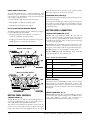
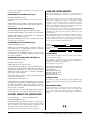
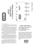
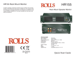
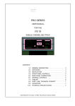
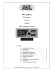
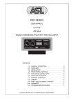
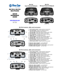
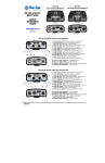
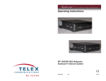
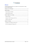
OPERATING INSTRUCTIONS
RS-501/502/522 BELTPACK
4065 Hollis St.,
Emeryville,CA 94608
Phone: (510) 496-6666
Fax: (510) 496-6699
www.clearcom.com
P/N 810054 Rev. G
Thank you for choosing Clear-Com. The Series 500 beltpack
intercom stations include a number of unique operating
features. The following information will assist you in getting
the most out of the unit for your specific application. Please
take the time to read this document and familiarize yourself
with the specific features of this beltpack.
Top View RS-501
A VOLUME CONTROL
D MIC ON INDICATOR
A
B TALK BUTTON
PRESS TO
O TALK-TWICE
ALK-TWICE TO
O LA
LATCH
TCH
TALK BUTTON (B) or (B & Q)
The talk button turns the microphone circuit on and off. It
also determines whether the circuit is switched on momentarily
or continuously.
For momentary action, press the talk button for the desired
length of time needed to talk on the connected headset’s
microphone, then release to deactivate.
For continuous (or “latching”) action, tap the talk button twice
in quick succession to lock the microphone on. To turn the
microphone off, press and release the talk button again.
Internal jumpers allow the selection of several operating modes
for the RS-502/522. See “User-Programmable Functions” on
pages 3–4 for more information.
E CALL LIGHT
CALL
CALL BUTTON (C)
When the call button is pressed, it transmits a call signal on the
intercom line that illuminates all other stations’ call indicator
lights on that channel.
C CALL BUTTON
Top View RS-502/522
OLUME CONTROL
CONTROL
A VOLUME
N
INDICA OR
D MIC ON INDICATOR
P
B
A
ALK BUTT
BUTTON
ON
B TALK
Q
PRESS TO
O TALK-TWICE
ALK-TWICE TO
O LATCH
LATCH
R
For RS-502 and RS-522 two-channel units: The call signal is
only sent to the channel (or channels) the unit is selected to
talk on. If no talk channel is selected, no call signal will be
transmitted.
INDICATOR LIGHTS (ALL ON TOP PANEL)
E CALL LIGHT
CALL
MIC-ON LIGHT (D) OR (D & P)
C CALL BUTT
BUTTON
ON
TOP PANEL CONTROLS
VOLUME CONTROL (A) OR (A & N)
The volume control adjusts the listen level of the incoming
intercom signal. The RS-501’s single channel requires a single
volume control. The RS-502 and RS-522 are two-channel
units that have a volume control for each channel. The
incoming audio level has no effect on the outgoing talk signal.
Its range is from full “off” (counterclockwise) to full “on”
(clockwise). Units built in 2001 and later contain an output
limiter. Contact the factory or check our Web site for serial
number reference. Contact the factory if you wish to suspend
this function.
RS-501/502/522 Beltpack Operating Instructions
The green mic-on LED indicates that the microphone circuit is
on. (For the RS-502/522 two-channel units, see “UserProgrammable Functions” on pages 3–4).
CALL LIGHT (E) OR (E & R)
The call light is a high-intensity, multi-element, red LED that
illuminates whenever a call signal is present on the respective
intercom line.
SPECIAL OPERATING INFORMATION
REMOTE MIC KILL (RMK)
With remote mic kill (RMK) you can turn a beltpack
microphone off from a remote location. This function is
activated by momentarily (50 ms) interrupting the DC power
to the beltpack. When power is restored to the beltpack, the
unit “defaults” to the mic-off condition.
1
MODEL IDENTIFICATION LABEL
All Series 500 beltpacks have a model identification label
mounted in a groove on the front of the unit. These labels are
color-coded for easy identification of the various models. The
color-coding of current models is:
• Orange: RS-501, single channel, monaural output.
from the intercom line. It is factory set for typical operation
but may be adjusted to suit the user’s preference.
MICROPHONE LEVEL SWITCH (G)
This switch selects between high gain (H) and low gain (L) for
the microphone input.
Normal operation is high gain. The low gain position improves
the signal-to-noise ratio in high noise environments. Low gain
is also appropriate with the higher output microphones in later
generation headsets.
• Blue: RS-502, two-channel, monaural output.
• Red: RS-522, two-channel, stereo output.
BELT CLIP AND SURFACE MOUNTING ADAPTER
An auxiliary surface mounting adapter is available upon request
for Series 500 beltpacks. Uses include:
• Mounting a beltpack to the underside of a counter or
console as a permanent operating position.
• Providing a convenient and secure temporary storage point,
usually adjacent to an intercom wall connector.
CONNECTOR
RELEASE BUTTON
H
INTERCOM LINE CONNECTORS (H & I)
RS-501: The 3-pin XLR-type female (H) and male (I)
intercom connectors connect to the Clear-Com intercom line.
They are wired in parallel. While the female connector is
normally used as the input, either one may be used as the input
or as a loop-through output.
RS-502/522: The 6-pin female connector (H) connects to the
Clear-Com intercom line. (The RS-522 does not have loopthrough to avoid confusion with the 6-pin male headset jack.)
Bottom View RS-501
J
BOTTOM PANEL CONNECTORS
RS-502: Connector “I” loops through to Connector “H.”
K
I
RS-502 TW/RS-522 TW (Not Shown): Same as RS-501
except that RS-522 has a 6-pin headset jack.
L
Intercom
Headset
FIGURE 1: INTERCOM LINE CONNECTOR WIRING
B
G
A
Clear-Com
H
SIDETONE ADJUST
L
Headset
Intercom
B
A
Clear-Com
SIDETONE
SIDET
ONE ADJUST
K
I
H
CONNECTOR
CONNECTOR
RELEASE B
BUTT
UTTON
ON
RS-501
RS-502/522
Pin#1
Common
Common
Common
Pin#2
+30 VDC
+30 VDC
+ 30 VDC/CH. A
Intercom
Pin#3
Intercom
CH. B Intercom
CH. B Intercom
RS-502/522 TW
SERIAL NUMBER
F
Bottom View RS-502/522
J
PIN#
Mic
G
Mic
H
F
L
L
Pin#4
CH. A Intercom
Pin#5
No connection
Pin#6
No connection
RELEASE BUTTON (J)
This button releases a male XLR-type cable connector that has
been plugged into the female intercom line connector (H).
Always use the release button to detach the connector. Forcing
the connector out without using the release button will damage
the beltpack.
SERIAL NUMBER
HEADSET CONNECTORS (K & L)
BOTTOM PANEL CONTROLS
SIDETONE CONTROL (F)
The RS-501 has only one sidetone control, although there is a
second empty adjustment hole. The second control is present
only on two-channel units (RS-502 and RS-522).
Headset Connector “K”: This 4-pin male XLR-type connector
is for headsets with dynamic microphones. The RS-522 has a
6-pin male XLR-type connector. (For instructions on
modifying beltpacks for electret headset mics, see page 4.)
The sidetone control adjusts how much the operator hears his
or her own voice in the earphone. It has no effect on the signal
going to the intercom line and negligible effect on the signal
2
RS-501/502/522 Beltpack Operating Instructions
REASSEMBLY
FIGURE 2: HEADSET CONNECTOR (K) WIRING
PIN#
RS-501
RS-502
Mic (L)
RS-522
Pin#1
Mic (L)
Mic (L)
Pin#2
Mic (H)
Mic (H)
Mic (H)
Pin#3
Hdphone (L)
Hdphone (L)
Hdphone Com
Pin#4
Hdphone (H)
Hdphone (H)
CH. B Hdphone (H)
Pin#5
CH. A Hdphone (H)
Pin#6
Hdphone Com
Headset Connector “L”: If the carbon-mic option is installed,
there is a 1/4 in. (6.3 mm) phone jack (tip/ring/sleeve)
mounted to the right of the 4-pin connector. Otherwise, there
is a plastic “knock-out” in that location.
The carbon-mic jack is for most types of headsets that use
carbon microphones or that are “carbon-compatible.”
OPTIONAL HEADSET CONNECTOR (L) WIRING
Tip: mic input
Ring: earphone output
Sleeve: common
DISASSEMBLY
Always disconnect the beltpack from the system before
disassembly.
1. Place the bottom-panel end of the beltpack (the end with the
connectors) face down on a flat surface. The component side of
the circuit board, with the multi-colored wiring, will be facing
you.
2. Slide in the left half of the black metal cover so that it covers
its half of the unit. The left side of the cover is the one with the
connector-release button. As you position the cover, the
connector-release button will be facing downwards. The
locating pins will guide you to correct placement of the cover.
3. Slide the insulating sheet between the metal cover and the
surface of the circuit board that is facing away from you.
4. Slide in the right half of the black metal cover. Place it on its
locating pins.
5. On the side of the unit facing you, slide the Clear-Com label
into the vertical groove on the black metal cover.
6. On the side of the unit facing away from you, slide the
beltclip into the vertical groove on the cover. This is best done
while holding the two sides of the cover together with one hand
and positioning the beltclip with your other hand. The closed
end of the clip should be on the top.
7. Again holding the two black metal sides of the unit together
with one hand, replace the top panel (the panel with the call
button). The locating pins will guide you to the correct
placement of the panel. (Take care not to damage the LEDs
while replacing the panel.)
NOTE: The jumpers for two-channel units with through-hole
design are on the component side of the main circuit board. (There
are no jumpers for this version of the RS-501.) The jumpers for all
models with SMT (surface mount) design are on the noncomponent side of the main circuit board.
5. Turn the unit upside-down so that now the bottom end is
facing you.
1. Place the top end of the beltpack (the end with the call
button) face down on a flat surface.
USER-PROGRAMMABLE FUNCTIONS
2. Remove the four corner screws on the connector plate. Do
not remove the screw at the center of the plate.
The Series 500 intercom stations include a number of
operating functions that can be programmed by the user. These
functions enable the Series 500 units to be customized to meet
the user’s needs. The listen and talk audio circuits, as well as the
indicator and call circuits, are controlled by the Clear-Com
logic integrated circuit.
3. Gently lift the connector plate up about 1/2 in. (12.7 mm)
and pull apart the two halves of the black metal cover, setting
them aside. Remove the insulating sheet.
4. Set the jumpers as required.
Consult the following chart for jumper location and function.
MODEL PCB TYPE
JUMPERS FUNCTION
LOCATION
RS-501
Through-hole
None
N/A
N/A
RS-501
SMT
JP-6
JP-7
Limiter
Electret Mic
Non-component side of
main circuit
board
RS-502/ Through-hole
522/TW
JP-2–JP-5 Programming Component
side of main
circuit board
RS-502/ SMT
522/TW
JP-2–JP-5 Programming Non-compoJP-7, JP-8 Limiter
nent side of
JP-12
Electret Mic main circuit
board
RS-501/502/522 Beltpack Operating Instructions
6. Slide in the four draw bolts and tighten them with a
screwdriver.
(RS-502 AND RS-522)
The functions are programmed by “opening” a jumper (cutting
a circuit board trace) or “closing” a jumper (connecting with a
wire) on the circuit board. Consult the chart in the
“Disassembly” section for jumper location. The jumpers are
labeled JP2, JP3, JP4, JP5, and JP12.
Normally the Model 502 is shipped from the factory
programmed for “two-channel select.” This means that the unit
can only talk on one of the two channels (A or B). Therefore
the user must “select” one of the two channels. Dual “listen” is
standard on the RS-502 beltpack. Both “listens” are always on
and are controlled by their respective volume controls. The
call-signal send button is only active on the selected talk
channel.
Normally the Model 522 is shipped from the factory
programmed to “simultaneous two-channel” operation. This
means that the unit can talk to both channels, either together
or separately. Dual “listen” is standard on the RS-522 beltpack
providing “split feed” to the headphones. Both listens are
always on and are controlled by their respective volume
3
controls. The call-signal send button is only active on the
selected talk channels.
PROGRAMMING THE INDICATOR LIGHTS (JP-2)
FACTORY DEFAULT: Closed.
CLOSED: Enables the green LEDs to operate as mic on/off
indicators.
OPEN: Enables the green LEDs to indicate which channel is
selected to listen and talk. (This is useful only with jumpers 3
and 5 closed.)
PROGRAMMING THE TALK FUNCTION (JP-4)
FACTORY DEFAULT: RS-502–Closed. RS-522–Open.
CLOSED: Enables TALKS to either Channel A or Channel B.
OPEN: Enable TALKS to both Channel A and Channel B
simultaneously, as well as selectively.
Note: When TALKING to both channels simultaneously, they are
not tied together as a party line.
PROGRAMMING THE LISTEN FUNCTION (JP-5)
FACTORY DEFAULT: Open.
OPEN: Sets both LISTEN circuits on. Listening volume on
each channel can be set individually. If desired, a channel’s
volume can be turned completely off.
CLOSED: Restricts the LISTEN circuits to operate on only
one channel at a time. Selecting a TALK channel will activate
that channel’s LISTEN.
PROGRAMMING THE BOUNCE-BACK FUNCTION (JP-3)
FACTORY DEFAULT: Closed.
CLOSED: Option disabled.
OPEN: With JP-5 open and JP-4 closed.
Latching Channel A’s TALK gives Channel A’s TALK priority.
Subsequently pressing Channel B’s TALK will activate Channel
B momentarily, until the button is released, at which time the
TALK function will “bounce-back” to Channel A. LISTEN is
always active on both channels.
Bounce-back will not operate if Channel B’s TALK is latched
or if Channel A’s TALK is off.
OPEN: With JP-4 and JP-5 closed.
Latching Channel A’s TALK and LISTEN gives them priority.
Subsequently pressing Channel B’s TALK will activate Channel
B’s TALK and LISTEN momentarily, until the button is
released, at which time the TALK and LISTEN functions will
“bounce-back” to Channel A.
Bounce-back will not operate if Channel B’s TALK is latched.
Other combinations are possible but offer limited usefulness.
ELECTRET HEADSET MIC MODIFICATION
For the RS-501: JP7
CLEAR-COM LIMITED WARRANTY
This Clear-Com product is guaranteed to be free from defects in
materials and workmanship for a period of two years from the date of
sale.
The Clear-Com warranty does not cover any defect, malfunction, or
failure caused beyond the control of Clear-Com, including
unreasonable or negligent operation, abuse, accident, failure to follow
instructions in the manual, defective or improperly associated
equipment, attempts at modification and repair not authorized by
Clear-Com, and shipping damage. Products with their serial numbers
removed or defaced are not covered by this warranty.
This warranty is the sole and exclusive express warranty given with
respect to Clear-Com products. It is the responsibility of the user to
determine before purchase that this product is suitable for the users
intended purpose.
Any and all implied warranties, including the implied warranty of
merchantability, are limited to the duration of this express limited
warranty. Neither Clear-Com nor the dealer who sells Clear-Com
products is liable for incidental or consequential damages of any kind.
For your own records, fill in the information below.
Model No.
Date Purchased
Purchased from (dealer)
Address
City
Serial No.
State
ZIP
FACTORY SERVICE
Do not return any equipment to the factory without first obtaining a
return authorization number.
All equipment returned for repair must be accompanied by
documentation stating the return address, telephone number, date of
purchase, and a description of the problem.
Send equipment to be repaired to:
Customer Service Department
Clear-Com Intercom Systems
4065 Hollis Street
Emeryville, CA 94608-3505
Telephone: (510) 496-6666
Fax: (510) 496-6610
Web site: www.clearcom.com
WARRANTY REPAIR
If in warranty, no charge will be made for repairs. Equipment being
returned for warranty repair must be sent prepaid and will be returned
prepaid.
NON-WARRANTY REPAIR
Equipment that is not under warranty must be sent prepaid to
Clear-Com. If requested, an estimate of repair costs will be issued
prior to service. Once repair is approved and repair of equipment is
completed, the equipment will be shipped freight collect from the
factory.
For the RS-502/522: JP12
FACTORY DEFAULT: Open
CLOSED: Will put approximately 5 VDC at .5 mA on pin 2
of the headset jack and reduce the gain of the mic pre-circuit.
This is suitable for most electret headset microphones. (An
attenuating circuit may be needed for some models.)
Note: The mic-level switch must be in the low (L) position.
4
RS-501/502/522 Beltpack Operating Instructions