1
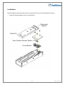
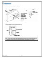
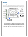
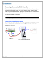
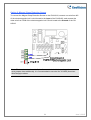
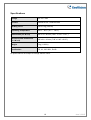
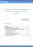
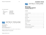
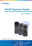
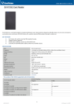
GV-ML1200 Electromagnetic Lock
The GV-ML1200 is a surface mount electromagnetic lock featured with a built-in voltage
spike suppressor and a sensor. It can be applied for single-leaf or double-leaf doors.
Packing List
1. GV-ML1200 electromagnetic lock x 1
2. Magnet faceplate x 1
3. Inner hexagon wrench x 1
4. M8 (41mm) screw + black rubber
spacer x 1
5. Hat nut x 1
6. Galvanized steel rivet x 2
7. Black rubber spacer x 2
8. Aluminum shim x 2
9. #10 (5/8”) screw x 2
10. #10 (1.25”) screw x 9
11. M4 (7mm) flat-head screw x 2
12. M5 (8mm) flat-head screw x 2
13. Washer x 3
14. Aluminum tube x 1
15. Tamper-proof tube x 3
June 3, 2015
1
Installation
Before installing, add the thread lockers to all screws. Be sure to firmly tighten the screws.
1. Install the electromagnetic lock to the doorframe.
Permanent
Magnet
Guide Pin
Door Position Sensor Switch
Circuit Board
2
June 3, 2015
2. Mounts the armature plate to the door.
Typical Installation of the electromagnetic lock:
Note: To make the armature plate adjust its proper position to the magnet automatically,
do not fix the armature plate too tightly and make the rubber washer more flexible.
June 3, 2015
3
Note: If the power switch is not wired between the DC source voltage and the magnet, it
will take longer to de-energize the magnet simulating residual magnetism.
Switch or
solid state
switching
device
Correct
Switch or
solid state
switching
device
Incorrect
4
June 3, 2015
Connecting to Power
Unscrew the cover of electromagnetic lock, and connect the lock to the output interface of
the GV-AS Controller and a power supply. Here we use GV-AS410 Controller as an example.
1. Power Terminal Block: Connects to a DC 12V / 24V power source. Connect the (+)
point on the electromagnetic lock to COM on GV-AS410, connect the two (-) points of the
electromagnetic lock and the external power supply together, and connect the (+) point on
the external power supply to NC on GV-AS410.
2. Power Switch Jumper: Plug the power jumpers to Pins A, C and Pins B, D for a 12V
DC power source. Plug the power jumper to Pins C, D for a 24V DC power source.
June 3, 2015
5
Note:
1. It is required to connect an external power supply if the total power consumption of the
output devices and readers connected to the GV-AS Controller exceeds 3A (for GVAS210 / 2110), 3.5A (for GV-AS410 / 4110) or 5A (for GV-AS810 / 8110).
6
GND
12V
GND
12V
GND
12V
2. You may use the power outputs on the GV-AS Controller when the total power
consumption of the output devices and readers connected to the GV-AS Controller is
under 3A (for GV-AS210 / 2110), 3.5A (for GV-AS410 / 4110) or 5A (for GV-AS810 /
8110). Here we use GV-AS410 Controller as an example.
June 3, 2015
Connecting a Sensor to the GV-AS Controller
There are two types of sensors for the electromagnetic lock: Door Closure Detection Sensor
and Magnet Clasp Detection Sensor. The sensors will detect whether the door is closed
tightly or not, and trigger a “Held Open” message on GV-ASManager when the door remains
unlocked. To connect the sensors to the GV-AS Controller, follow the steps below. Here we
use GV-AS410 Controller as an example.
Note: Only one type of sensor could be applied at a time.
Option 1: Door Closure Detection Sensor
To connect the Door Closure Detection Sensor to the GV-AS410, connect the Red wire of the
sensor to the Input of the GV-AS410, and connect the Black wire of the sensor to the
Ground of the GV-AS410.
June 3, 2015
7
Option 2: Magnet Clasp Detection Sensor
To connect the Magnet Clasp Detection Sensor to the GV-AS410, connect one wire from NC
of the electromagnetic lock’s circuit board to the Input of the GV-AS410, and connect the
other wire from COM of the electromagnetic lock’s circuit board to the Ground of the GVAS410.
Note: The two wires mentioned in Option 2 are not included in the package; the users
must prepare them additionally. It is recommended to use wire No. 26 AWG (American
Wire Gauge) or above.
8
June 3, 2015
Setting the Web Interface of the GV-AS Controller
Here we use GV-AS410 Controller as an example.
1. To configure the input setting of connected sensor: on the Web interface of the GV-AS410,
select Advanced Setting, select Input Configuration, and set the input function to Door
Contact.
2. To configure the output setting of the electromagnetic lock: on the Web interface of the
GV-AS410, select Advanced Setting, select Output Configuration, and set the output
function to Electric Lock.
For details on configuring the input and output devices, see the Input Configuration and
Output Configuration section in Chapter 8 of the GV-AS Controller User’s Manual.
June 3, 2015
9
Specifications
Voltage
DC 12V / 24V
Current
500mA at 12V / 250mA at 24V
Holding Force
544.311 kg (1200 lb)
Operating Temperature
-20°C ~ 60°C (-4°F ~ 140°F)
Dimensions (L x W x H)
266 x 73 x 40 mm (10.47” x 2.87” x 1.57”)
Armature Plate Dimensions
(L x W x H)
185 x 61 x 16 mm (7.28” x 2.40” x 0.62”)
Weight
5 kg (11.02 lb)
Certification
CE, UL, ISO 9001, RoHS
All specifications are subject to change without notice.
10
June 3, 2015