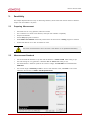
1
ViVIX-S Service Guide © Vieworks. 2014 All rights reserved. Under copyright laws, this manual may not be reproduced, in whole or in part, without the written permission of Vieworks. ViVIX-S Service Guide Contents 1. Document Guide ............................................................................................................... 3 1.1 Symbols ....................................................................................................................................... 3 1.2 Notation ...................................................................................................................................... 3 2. Performance Inspection Guide ...................................................................................... 4 3. Self-Diagnosis .................................................................................................................... 5 4. Resolution Measurement ................................................................................................ 6 4.1 Preparing Measurement .......................................................................................................... 6 4.2 Measurement Standard ........................................................................................................... 6 4.3 Measurement Sequence .......................................................................................................... 7 5. Sensitivity ........................................................................................................................... 8 5.1 Preparing Mesurement ............................................................................................................ 8 5.2 Measurement Standard ........................................................................................................... 8 5.3 Measurement Sequence .......................................................................................................... 9 5.4 Checking the Result of Measurement .................................................................................. 9 6. Calibration ........................................................................................................................10 6.1 Preparing Calibration ............................................................................................................. 10 6.2 Starting Calibration ................................................................................................................ 10 6.3 Offset Calibration .................................................................................................................... 11 6.4 Gain Calibration....................................................................................................................... 12 6.5 Defect Calibration ................................................................................................................... 13 6.6 Checking the Calibration Result........................................................................................... 14 7. Revision History ..............................................................................................................15 Rev.1.0 Page 2 of 15 RA14-146-026 ViVIX-S Service Guide 1. Document Guide This Service Guide includes various information to forge and operate Vieworks’ detectors. Target This Service Guide is intended for service engineers who maintain and inspect the Vieworks’ detector after its installation. With this document, the service engineer can fully understand about technical contents of Vieworks’ detectors. Contact Department For any comments or inquiries regarding this document, please contact via e-mail below. 1.1 Item Contents Department Technical Support Division in Vieworks E-mail [email protected] Symbols While using Vieworks’ products, follow the safety instructions in this manual along with the warning or caution symbol. It is important for you to read and understand the contents with the following symbol for operating the products safely. Information This symbol is used to indicate reference and complementary information related to the product. The service engineer should read the instructions of this symbol carefully. 1.2 Notation Bold types We applied bold font style to the words which indicated products terms, or the words and sentences which are needed to transmit clear meaning. This helps you to easily distinguish the words from other technical ones for explaining functions, and UI (User Interface) of the program as well as the emphasis contents. Rev.1.0 Page 3 of 15 RA14-146-026 ViVIX-S Service Guide 2. Performance Inspection Guide During periodic inspection, the service engineer should inspect the detector and check uniformity of the image quality. In addition, be sure to process calibration in case the image quality is deteriorated during the inspection. The items of performance inspection are as follows. Item Period Description Conduct self-diagnosis from the Setup program for the internal devices of Self-Diagnosis Half-yearly the detector and check their states. Refer to <3 Self-Diagnosis> for the way of self-diagnosis. Check the resolution of the detector through resolution chart or using a Resolution Half-yearly phantom. Refer to <4 Resolution Measurement> for the way of resolution measurement. Evaluate the characteristic of the detector through checking pixel values of Sensitivity Half-yearly the image made by responding to X-ray dose which reaches to the surface of the detector. Refer to <5 Sensitivity> for the way of sensitivity evaluation. Updating calibration data. (Offset Gain Defect) Calibration Half-yearly Proceed to calibrate when X-ray Generator, Tube, Collimator or exposure environment are changed. Refer to <6 Calibration> for the way of calibration. Rev.1.0 Page 4 of 15 RA14-146-026 ViVIX-S Service Guide 3. Self-Diagnosis [TBD] Rev.1.0 Page 5 of 15 RA14-146-026 ViVIX-S Service Guide 4. Resolution Measurement This chapter instructs how to measure image resolution of the product. 4.1 Preparing Measurement Check the condition of X-ray generator and console. Check the condition of X-ray tube. It is recommended to check if the X-ray dose is accurate by using a dosemeter. Prepare the resolution chart. Vieworks recommends the following resolution charts. Manufacturer: Test pattern from Fluke Biomedical. Model 1: 07-526 (0.6-10.0 lp/㎜, 0.05 ㎜ Pb) Model 2: 07-535 (0.6-5.0 lp/㎜, 0.05 ㎜ Pb) Pre-install the Setup program. Read ViVIX-S User Manual to be fully aware of the Setup program in advance. Preheat the detector at least 30 minutes after supplying power to the detector. The measurement result can be inaccurate unless the detector is preheated fully. 4.2 Measurement Standard A raw image file is used for the resolution measurement. The tube voltage of X-ray generator is 70 ㎸ while acquiring images. SID between the X-ray generator tube and the detector is 150cm while acquiring images. The pixel value of the acquired image should be formed within 2000±200. The resolution should be measured 3.5 lp/㎜ or more through the visual identification. Since the Pixel Pitch of Vieworks’ detector is 0.14㎜ (140㎛), the maximum resolution is 3.571 lp/㎜. This means that the resolution cannot be measured 3.6 lp/㎜ or more in theory. If the resolution chart is put on the detector diagonally, the resolution can be measured 4.0 lp/㎜ in maximum. Rev.1.0 Page 6 of 15 RA14-146-026 ViVIX-S Service Guide 4.3 Measurement Sequence 1 Adjust SID as 150㎝ between the detector and X-ray tube. 2 Put the resolution chart on center of the detector diagonally. 3 Execute the Setup program and move to the Diagnosis dialog. 4 Set the tube voltage of X-ray generator as 70㎸ or less and then acquire an image. If the image is saturated or unclear, acquire an image again by setting the tube voltage low. 5 While acquiring images, adjust the X-ray dose condition (㎃ or ㎳) until the surrounding pixel value of resolution chart is formed as 2000±200. 6 When the exposure condition is completed to adjust, take X-rays for measuring image resolution. 7 Magnify the acquired image with 3.7 lp/㎜ area of resolution chart as the center. 8 Check the resolution by visual identification. If the measurement result is inconsistent with the standards, check the exposure condition and environment, then try to measure the resolution 2 or 3 times again. Contact Vieworks if the result is still discrepant to the standards. Rev.1.0 Page 7 of 15 RA14-146-026 ViVIX-S Service Guide 5. Sensitivity This chapter explains about the way of measuring sensitivity which shows the reaction extent of detector output over the incident X-ray dose. 5.1 Preparing Mesurement Check the state of X-ray generator, tube and console. Put a collimator on center of the detector, and open the collimator completely. Prepare a dosemeter. Set the Setup program in advance. Read ViVIX-S User Manual and be fully aware about the instructions of Setup program in advance. Preheat the detector for at leat 30 minutes or more. The result of measurement can be incorrect if the detector is not preheated sufficiently. 5.2 Measurement Standard The recommend SID between X-ray tube and the detector is 130cm~150 ㎝ while taking X-rays. The tube voltage of x-ray generator is between 70 ㎸ ~ 80 ㎸ while taking X-rays. The measurement is based on pixels in the center of image, and Pixel Value is formed between 2000±200. The normal range of Sensitivity is 90% or more of the minimum value, and 110% or less of the maximum value written in ViVIX-S 1417W Specifications. Rev.1.0 Page 8 of 15 RA14-146-026 ViVIX-S Service Guide 5.3 Measurement Sequence Making an exposure as adjusting the X-ray condition until the satisfying Pixel Value is formed from 1 Diagnosis menu in the Setup program. 2 When the exposure condition is completed to be adjusted, measure X-ray dose by a dosemeter and record it. The unit is uGy. Calculate the result of Sensitivity as dividing Pixel value by X-ray dose (uGy). 3 The condition is Gain Type = 1. Refer to the following fomula. Pixel value = A x (X-ray Dose[uGy]) + B A (Sensitivity) = Pixel value / uGy B (Offset) 4 If Gain Type is not 1, divide Pixel value by the result value as much as the configured magnification of the following Gain Type. 5.4 Gain Type 0 1 2 3 1417WA (CsI) 0.62 1 1.14 1.33 1417WB (Gadox) 0.86 1 1.2 1.5 Checking the Result of Measurement Contanct the service engineer if the result value of Sensitivity is less than 90% of the minimum value or more than 110% of the maximum value written in ViVIX-S 1417W Specifications. (𝑚𝑚𝑚𝑚𝑚𝑚𝑚𝑚𝑚𝑚𝑚𝑚𝑚𝑚 𝑙𝑙𝑙𝑙𝑙𝑙𝑙𝑙𝑙𝑙) 𝑋𝑋 90% < � 𝑃𝑃𝑃𝑃𝑃𝑃𝑃𝑃𝑃𝑃 𝑉𝑉𝑉𝑉𝑉𝑉𝑉𝑉𝑉𝑉 𝑋𝑋 −𝑟𝑟𝑟𝑟𝑟𝑟 𝐷𝐷𝐷𝐷𝐷𝐷𝐷𝐷 𝐺𝐺𝐺𝐺𝐺𝐺𝐺𝐺 𝑅𝑅𝑅𝑅𝑅𝑅𝑅𝑅𝑅𝑅 � < (𝑚𝑚𝑚𝑚𝑚𝑚𝑚𝑚𝑚𝑚𝑚𝑚𝑚𝑚 𝑙𝑙𝑙𝑙𝑙𝑙𝑙𝑙𝑙𝑙) 𝑋𝑋 110% Refer to the following example. 1417WB (Gadox) Gain Type = 2 Pixel Value = 2152 X-ray dose = 16uGy Sensitivity = (2152 / 16) / 1.2 = 112.292 Result: 112.292 > 90% of the minimum value Normal Refer to ViVIX-S 1417W Specifications about the min./max. specifications of Sensitivity. Rev.1.0 Page 9 of 15 RA14-146-026 ViVIX-S Service Guide 6. Calibration This chapter instructs how to calibrate the detector while the service engineer acquires images, and how to create calibration data with calibration. Refer to ViVIX-S User Manual on how to calibrate the detector by loading calibration data provided by Vieworks. 6.1 Preparing Calibration Precheck the condition of X-ray generator and console. Precheck the condition of X-ray tube. It is recommended to check if the X-ray dose is accurate by using a dosemeter. Preheat the detector at least 30 minutes after supplying power to the detector. The measurement result can be inaccurate unless the detector is preheated fully. Pre-install the Setup program. Read ViVIX-S User Manual to be fully aware of the Setup program use and calibration way in advance. In case the service engineer cannot create calibration data directly, it is recommended to prepare the calibration data CD provided by Vieworks and save the data to a specific folder of PC. 6.2 Starting Calibration 1 Supply power to the detector and wait for 30 minutes or more. 2 Execute the Setup program and check if the serial number of connected detector is correct. As the serial number of detector is the only information that recognizing the calibration data, it is recommended to record it separately before calibrating the detector. Rev.1.0 Page 10 of 15 RA14-146-026 ViVIX-S Service Guide 6.3 Offset Calibration Post-offset Calibration 1 Set the number of Stage as 10 in the Post-offset Calibration area. 2 Click Run Post-offset Calibration button and progress Post Offset calibration. 3 Save the Post Offset calibration data as a file after the Post Offset calibration is completed. Follow the generation rule of a calibration data file name when saving the calibration data as a file. Refer to ViVIX-S User Manual for the generation rule of a calibration data file name. Rev.1.0 Page 11 of 15 RA14-146-026 ViVIX-S Service Guide 6.4 Gain Calibration 1 Put a collimator on center of the detector, and open the collimator completely. 2 Adjust SID as 130㎝ ~ 150㎝ to make X-ray exposure range include the detector. 3 Remove any objects or foreign materials between the tube and the detector. 4 Choose Gain Calibration -Normal. 5 Set the tube voltage of X-ray generator as 70㎸ ~ 80㎸. 6 While acquiring images, adjust the X-ray dose condition (㎃ or ㎳) until Current Value of the Gain Calibration area is formed between 2000±200. 7 Set the exposure number of Stage as 10 when the adjustment of exposure condition is completed. 8 Click Get button, and keep making an X-ray exposure at 15 sec intervals. 9 Save the Gain calibration data as a file. Make sure to progress Gain calibration again if the cases below are applicable. When the settings of Exposure Section or Gain Type is changed from the Setup program. When the exposure devices like X-ray generator are repaired. When the exposure environment is changed. When the service engineer decides that it is need to progress Gain calibration. Rev.1.0 Page 12 of 15 RA14-146-026 ViVIX-S Service Guide 6.5 Defect Calibration 1 Choose Defect Calibration –Normal in the Calibration window. 2 Click Defect Correction button and progress Defect calibration. 3 Save the Defect calibration data as a file after the Defect calibration is completed. Refer to ViVIX-S User Manual for the detailed information about Defect calibration. Stop proceeding Defect calibration if new defect is not displayed in the detector, and maintain the existing settings of Defect Map data. Rev.1.0 Page 13 of 15 RA14-146-026 ViVIX-S Service Guide 6.6 Checking the Calibration Result 1 Move to the Diagnosis window in the Setup program after completing calibration. 2 Adjust the exposure condition as the image pixel value (Gray Level) is formed 2000±200, and acquire images. 3 Check the acquired image. 4 Complete the calibration if the image is FLAT. 5 If the image is improper, progress Post Offset and Gain Offset again. Image State Normal FLAT Image Vertical Line Offset Fail Vertical Line Result OK Failure Failure After the calibration, it is recommended to check the image quality from the Setup program as well as from the acquisition software viewer actually used. Rev.1.0 Page 14 of 15 RA14-146-026 ViVIX-S Service Guide 7. Revision History Ver. Date Descriptions 1.0 2014-09-23 Initial Release Vieworks.Co.,Ltd #107-108, 601-610 Suntechcity 2 52 Sagimakgol-ro (307-2 Sangdaewon-dong) Jungwon-gu, Seongnam-si, Gyeonggi-do, 462-736 South Korea Telephone: +82-70-7011-6161 Fax: +82-31-737-4954 Homepage: http://www.vieworks.com European representative: DONGBANG ACUPRIME 1 Forrest Units, Hennock Road East, Marsh Barton, Exeter EX2 8RU, UK Telephone: +44(0)-1392-829500 Homepage: http://www.acuprime.com Rev.1.0 Page 15 of 15 RA14-146-026