1
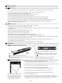
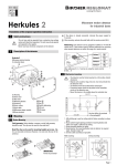
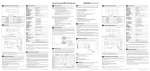
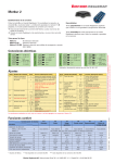
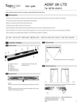
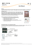
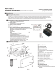
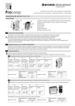
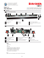
This product meets or exceeds ANSI standard 156.10 as independently tested by TÜV Rheinland North America TopScan User Manual Active infrared door-mounted safety sensor for swinging, low-energy, revolving & folding doors Introduction 1 1.1 Parts of the TopScan Assembly A C B E D D E D F A B Shown is TopScan III 36” in silver with right cable exit. Actual configuration may vary. A End cap screws (2x) B End caps (2x) G C Aluminum rail E D F Sensor unit (3x) G Intra-unit connector cable (2x) 8-ft (2.4 m) 6-wire cable for door operator Lens cover 1.2 Parts of the Single Sensor S O N H H I J K R Q I Snap-in mounting brackets (2x) Infrared sender lens Detection indication LED (red) DIP switches P O J L M N O N K L M Height/distance adjustment thumb wheel Infrared receiver lens Mounting bracket connecting pin (2x) Connector for intra-unit cable (2x) 1.3 Tools / Parts required for Installation Tools: - Ladder - Tape measure - Level - Wire cutter - 4 gauge (5 mm dia.) wire stripper for cable sleeve - 22 gauge (0.25 mm²) wire stripper for single wires - Flathead screwdriver 1/10” (size #0 / 2.4 mm) - Electric screwdriver with phillips head(size #2) - Electric drill with 1/4” (6 mm) drill bit Parts: - 2 or 3 screws (e.g. self-tapping) to attach aluminum rail to door panel Page 1 H P Q R S Wiring terminal block Cable exit Extension connector Left/right pattern position selector 2 Safety Precautions 2.1 General Safety Warning: failure to follow these safety precautions may cause damage to sensor or objects, serious personal injury, or death. -This product is designed to be mounted on the top of a swinging, revolving, or folding automatic door. -Do not use this product other than for its specified application. -Observe all local, national, and international door safety standards, codes, and laws. -Only trained and qualified personnel may install and initialize the sensor. -Only authorized Bircher Reglomat personnel may perform hardware/software changes or repairs to the product. -The unit should only be operated from a safety extra low voltage (SELV) system with safe electrical separation. -Always consider the safety functions of your applications as a whole, never just in relation to one individual section of the system. -The installer is responsible for testing the system to ensure it meets all applicable safety standards (e.g. ANSI 156.10). -Never touch any electronic components or lenses. 2.2 Installation Safety -Follow all steps outlined in this manual in order for proper installation of the product. -Stop all pedestrian traffic through the door before installing sensor. -Ensure there is no pedestrian traffic through the door until sensor is installed and tested for compliance with all applicable safety standards (e.g.ANSI 156.10). -Verify proper installation of door equipment before installing sensor. -Shut off all power before attempting any wiring procedures. -Always use wire terminals to terminate stranded wire ends. -Check placement of wiring to ensure moving parts are not impeded by wires. -Make sure wiring is correct before applying power to the sensor to avoid damage to equipment. -Ensure (e.g. by standing in the pattern) that installation is in compliance with all applicable standards (e.g. ANSI 156.10) after installation. -If the sensor sustains damage (e.g falls), replace it with a new unit. -If a satisfactory solution cannot be achieved after troubleshooting a problem, please call Bircher Reglomat at 800-252-1272 or visit our website at www.bircherreglomat.com. DO NOT LEAVE ANY PROBLEMS UNRESOLVED! DO NOT SACRIFICE SAFETY FOR ANY REASON! 3 Perparation Opening Housing & Removing Sensor 3.1 1 1 Loosen both red mounting bracket screws 2 1 2 Remove the end caps by removing both screws Remove the front cover by grasping with your fingers and pulling away from aluminum rail. 3.2 Mounting the Housing Slide both mounting brackets slightly to their side and remove the sensor from the aluminum rail. Alternate method: slide sensor unit with attached brackets out the side of the aluminum housing 1. Fix both end caps to the aluminum rail with provided screws. Loosen mounting bracket screws and slide sensors to the side to accomodate holes. 2. Center aluminum rail with end caps between door jambs or hinge and place about 1” (2.5 cm) ....from the top of the door or arm fixture/slide rail (if applicable). 3. Drill mounting holes in the aluminum rail and possibly door panel (2 holes for ≤ 36”, 3 holes for ≥ 36”) approximately 5”(12 cm) from the edges. 4. Attach the aluminum rail to the door panel with screws (e.g. self-tapping). Note: If the TopScan assembly is too long for the door, the aluminum rail & lens cover may be cut down to size. For ease of cutting, ensure lens & rail are cut together as an assembly. 5. Route the cable through the cable exit in the end cap and lead to door operator (e.g. through supplied cable loop.) 6. If mounting a TopScan system (units on both sides of door face) drill a 1/4” cable hole approximately 7” (18 cm) from the edge. Units must be mounted at the same height to route the cable properly. For more information on wiring TopScan systems, see section 4.2. Page 2 3.3 Selecting the Detection Area Depending on the door opening, a right or left sensing location must be selected. The selector can be found on the backside of the optics. Front 4 To change the detection area, slide the plastic selector to position L or R.* Right* Left * Back Position of the detection area L = Left R = Right * *Factory setting Electrical Connection 4.1 Single TopScan Sensor Pre-assembled TopScan Self-Assembly - /~ 1 2 3 4 5 6 + /~ common NC NO Test input/ 1 monitoring 1 1. Remove the existing unwired terminal block by pushing it out from the back with a screwdriver if necessary. 2. Attach the pre-wired terminal block to the terminal receptor pins on the sensor unit. Black Red White Brown Green Cable Monitoring available in stationary mode only - 17 - 37 VDC/ Power + 18 - 26 VAC COM NC NO Blue 1 4.2 Safety signal Monitoring 1 Monitoring available in stationary mode only TopScan System An additional TopScan mounted on the opposite side of the door panel can be connected through the extension connector (terminals 7–12). Wire colors refer to the pre-installed 6-wire cable provided with TopScan assemblies. Pre-installed 6-wire cable Drill hole through aluminum rails & door for cable feed DOOR OPERATOR Pre-installed 6-wire cable 2 wiring changes to be made Power 17-30 VDC/ 18-28 VAC + COM Approach side safety signal NO (NC) White Green Swing side safety signal Blue Brown COM NO (NC) Pre-installed 6-wire cable from other door face Black Red Cable ! BROWN - re-routed from 4 12 11 10 ! BLUE - re-routed from 6 9 8 7 Page 3 1 2 3 4 5 6 BLACK - power - /~ RED - power + /~ WHITE - common GREEN - sensor signal GREEN - sensor signal 12 11 WHITE - sensor signal 10 9 RED - power + /~ 8 BLACK - power - /~ 7 1 2 3 4 5 6 Completing the Assembly 5 5.1 Mounting the Sensor(s) in the Housing 2 1 1. Loosen the red .... screws on the .... mounting brackets. 3. Slide the sensor into position between the brackets. 2. Click the mounting brackets into the aluminum rail. Brackets can also be clicked out if screws are sufficiently loosened. Note: for a denser detection pattern, mount multiple sensors on one aluminum rail and connect with intra-unit flat cables. 5.2 Insert the intra-unit flat cable connector correctly into the receptacle or damage could result. Routing the Cable Route the wires from the screw terminal away through the cable exit guide. 4. Move the brackets toward sensor and apply pressure until the pins snap into the sensor. Tighten screws to secure. Lead the cable behind the sensor and out the end of the assembly. Route cable out of unit according to cable loop location (right or left). Sensor Adjustments 6 Power on the sensor after installation is complete. The LED illuminates when the sensor detects a presence. 6.1 Selecting the Operating & Switching Modes Typical setting for swing door shown *Factory settings Switch 2 - Switching mode selection Switch 1 - Operating mode selection *Up 1 2 Moving mode (background suppression on) e.g. 1 mounted 2 1 2 on swing 1 2 door panel – No background necessary, floor is ignored * Up 1 2 1 2 1 2 (background suppression) – No monitoring: the sensor cannot be tested in this ....operating mode (test input TI without function) Down 1 2 1 2 Stationary mode (background analysis) e.g. 1 mounted 2 1 2on machine 1 2 1 – A stable background is essential, the floor is analyzed (background evaluation) – Monitoring possible: the sensor can be tested via ....the test input Down 2 Page 4 1 2 1 2 Passive Switching –1 The 2 relay opens the NO contact (closes the NC) on detection (see section 3.4) – A power failure or wire damage is interpreted as a detection and will trigger the respective safety feature of the door Active Switching – The relay connects NO to COM on detection ....(see section 3.4) 6.2 Scanning Range Adjustment Increasing the scanning range First, check the scanning range with a white letter size sheet of paper or the palm of your hand. Then, adjust the scanning range with the thumb wheel. Recommended height setting is 10” - 25” (25 - 64 cm) Moving pattern away from floor Decreasing the scanning range Moving pattern closer to floor Background / Floor 6.3 Detection Area Adjustment Adjust the detection area by sliding the sensor in the rail. The red screws on mounting brackets should be partly loosened for easy adjustments. Ensure red mounting bracket screws are sufficiently loosened to move over aluminum rail mounting screw heads. 6.4 Inclination Angle Adjustment Using both hands, grasp both sides of the sensor and carefully tilt it up or down to change the inclination angle. Scale 1 click = 3° The angle (0° to 30°) can be read on the sides of the mounting brackets. 2m 7' (84'' = 210 cm) 30° 15° 0° 0 to 30° ° 0 to 30 30° Ensure the0 àsensor is level by setting the same angle on both brackets. 4' (48'' = 120 cm) 1.15 m 7' (84'' = 213.4 cm) 6.5 Adaptation to Meet Standard Requirements To comply with ANSI/BHMA requirement for the leading edge and sensing field, cut the protruding pin of the mounting bracket on the leading edge and slide the sensor/brackets assembly as far as possible towards the leading edge. The TopScan has been independently tested by TÜV Rheinland North America and certified compliant with ANSI standards. After installation it is important to test the full detection pattern described in the standard by standing/crouching in the detection area. Page 5 7 Finishing the Installation 7.1 7.2 Securing the Sensor Position When all settings are complete, secure the sensor by tightening the red screws on the mounting brackets. A screwdriver can be used for tightening the screws, but only very low torque should be applied. Closing the Housing Remove the blue plastic protective film from the lens. 1. Attach the front cover to the aluminium housing. 2. Attach the end caps using the screws provided. 1 Click the plastic front cover onto the rail as shown. Ensure it is secure the entire length of the rail. 7.3 Routing the Cable Loop Use pliers to break out one of the two the cable exits indicated on the end cap. 8 Route the cable loop through the cable exit. Troubleshooting Note: The door opening refers to the TopScan on the SWING side. The door closing refers to the TopScan onthe APPROACH side. LED Fault Remedy Off Door does not open/close 1. Change the switching mode (active/passive), see section 4.1 Or use the other relay output terminal (NC instead of NO or vice versa), see section 4.1 Off The sensor does not detect the test object 1. Adjust scanning range closer to the floor, see section 4.2 2. Check intra-unit cable & connectors, see section 3.5 3. Replace sensor On Door does not open/close 1. Adjust scanning range further away from the floor, see section 4.2 Door opens/closes 1. Change the switching mode (active/passive), see section 4.1 Or use the other relay output terminal (NC instead of NO or vice versa), see section 4.1 and adjust scanning range further away from the floor, see section 4.2 Door only opens/closes cyclically or partially (irregular detection without an object in the scanned zone) 1. Change the operating mode to moving, see section 4.1 2. Adjust the scanning range further away from the floor, see section 4.2 3. Increase inclination angle further away from the door panel, see section 4.4 4. Remove reflective background (e.g. dry the floor or cover floor with mat) 5. Remove the fluorescent lamp (e.g. deactivate FL/CFL/HID bulb in the immediate vicinity of the sensor/door On On and off intermittently Page 6 2 8 FCC Approval This device complies with Part 15 of the FCC Rules and with RSS-210 of Industry Canada. Operation is subject to the following two conditions: - This device may not cause harmful interference. - This device must accept any interference received, including interference that may cause undesired operation. This equipment has been tested and found to comply with the limits for a Class B digital device, pursuant to Part 15 of the FCC Rules. These limits are designed to provide reasonable protection against harmful interference in a residential installation. This equipment generates, uses, and can radiate radio frequency energy and, if not installed and used in accordance with the instructions, may cause harmful interference to radio communications. However, there is no guarantee that interference will not occurr in a particular installation. If this equipment does cause harmful interference to radio or television reception, which can be determined by turning the equipment off and on, the user is encouraged to try to correct the interference by one or more of the following measures: - Reorient or relocate the receiving antenna. - Increase the separation between the equipment and receiver. - Connect the equipment into an outlet on a circuit different from that to which the receiver is connected. - Consult the dealer or an experienced radio/TV technician for help. Warning: Changes or modifications to this equipment not expresssly approved by Bircher Reglomat may void the FCC authorization to operate this equipment. 9 10 Additional Parts & Accessories AIR16 RE sensor Sensor mounting bracket Intra-unit flat cable available in 12”, 18”, 24” & 35” to connect multiple sensors in one housing 8’ (2.4 m) 6-wire cable to connect TopScan to door operator Aluminum rail available in black, white or silver Lens cover End caps Rain protection tapefor areas exposed to rain Declaration of Conformity Manufacturer: Importer: Cable loop to protect exposed cables Bircher Reglomat AG, Wiesengasse 20, CH-8222 Beringen, Switzerland, www.bircher-reglomat.com Bircher America, Inc. 870 Pratt Ave N, Schaumburg, IL 60193, USA, www.bircherreglomat.com Directives observed: 2006/42/EC, R&TTE directive 1999/5/EC, EMV-directive 004/108/EC Standards taken into account: EN 61000-6-1, EN 61000-6-2, EN 61000-6-3, EN 61000-6-4 Important note: Bircher Reglomat reserves the right to change any information in this document without notice. For the latest version, please visit www.bircherreglomat.com or call 800-252-1272 to request a copy. Page 7 Technical Data Specification Technology Value Active infrared (wavelength: 880 nm) Triangulation principle IR spot dimension Approx. 3“ (75 mm) in diameter for scanning range of 80“ (2000 mm) Detection distance (measured from sensor) Scanning range setting Stationary mode: approx. 4“ - 100“ (100 - 2500 mm) Moving mode: approx. 20“ - 100“ (500 - 2500 mm) Thumb wheel approx. 60“ - 100“ (1500 - 2500 mm) Deviation from 68º F (20º C) 140º F (60º C): + 10% -4º F (-20º C): - 10% Max 20% White: longer scanning range Black: shorter scanning range Temperature dependence (with reference to the set scanning range) Black/white difference (with reference to scanning range set) Monitoring input (labeled test input) Response time upon detection Response time with test signal Activated with 17 - 30 V DC against power - (for stationary mode only) Approx. 30 ms Max. 500 ms - only possible with DC operation Operating voltage Current consumption 17 - 37 V DC / 18 - 26 V AC <110 mA Output Relay, changeover (Form C/SPDT) contact 48 V AC/DC Current Nominal: (ohmic load) 1A (24V DC) Ind./cap. load: provide spark quenching 0.5 A AC/DC Max. switching power: 55VA/24W Mounting height 5.5’ - 8.8’ (1.7 - 2.7 m) Protection class Suitable for use in acc. to NEMA 5 (IP52) in housing with aluminum rail + cover + endcaps Rail Aluminum Lens cover PC (black) Sensor ABS Operating temperature ‚-4º F to 140º F (-20º C to 60º C) Storage temperature ‚-40º F to 176º F (-40º C to 80º C) Dimensions (sensor only) L x W x H without housing 7 3⁄4“ x 1 1⁄4“ x 3⁄4“ (198.5 x 31 x 20 mm) Dimensions (housing inc. end cap) W x H (length variable) 1 1⁄2“ x 1 3⁄4“ (38 mm x 44 mm) Material Weight finished TopScan III 36” assembly 1 lb, 8 oz (0.68 kg) sensor unit only 1.59 oz (45 g) Bircher Reglomat 870 Pratt Avenue N Schaumburg, IL 60193 Phone: 847-952-3730 Toll-Free: 800-252-1272 Fax: 847-952-2005 Email: [email protected] Web: www.bircherreglomat.com US03 009D 6/13 11