1
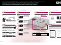
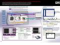
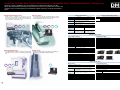
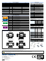
DM3100 Solutions
Application-specific Portable Data Capture Systems
built on the DM3100 Data Platform
PC
Measurement
Digital
Oscilloscope
PC-based
Data Logger
Data Recorder
& Logger
Made Easy!
DM Style!
Fast & Furious
Like No Other
The New Concept DM3100, at the Heart of all the DPM System Configurations
DATA PLATFORM MANAGEMENT
DM
The DM3100 Series Data Platform is a new type of measurement device that combines the superior advanta ges of computer-based
measurement with those of a standalone device. It offers features such as plug-in amps with high noise resi stance, the use of
synchronous input/output cables to enable multi-channel measurement synchronized on the time axis, data storage functions to
accurately capture important data, and networkability to meet various user needs in a wide range of measur ement scenarios.
1
Request
3
Easy Measurement Using a PC
Request
Make Use of Ethernet and USB Connectivity
4
Ability to Capture Different Measurement Phenomena
Request
A Wide Range of Isolated Plug-in Amplifiers to Suit Your Application Needs
Ethernet LAN connectivity enables remote operation and data
measurement, while USB connectivity facilitates measurement
setups.
e
tag
Vol ement
sur
mea
LAN
Solutions
5
Long-term Data Capture
Request
On-site Standalone Measurement Without Using a PC
Choice of Memory Devices for Reliable Data Capture
Attach the Monitor to Turn Your DM3100 into a Standalone Model
Data is captured directly to the DM3100’s internal memory devices.
Select the data storage device that best suits your application.
This is the perfect solution for those times when you don’t want to take your
PC to the measurement site, or when you don’t need to use your PC for
measurement. The standalone model is light and easy to carry.
40 GB hard disk
DM3-V amplifier
1 MS/s max sampling speed,
50 mV to 200 V input voltage
Ideal for long-term data capture,
and for multi-point measurement.
Hub
Notebook computer
/
age
Volt erature
p
nt
temasureme
USB
me
in
Stra ment
2
Request
sure
mea
Increased Number of Measurement Points
.
AX
Synchronous Linking for Multi-channel Operation M64ch
Up to 8 DM units can be linked together with
synchronous data input/output cables for synchronized
measurement on the time axis on up to 64 channels.
Each unit is connected via Ethernet or USB, and
controlled by the PC. (Synchronous linking can only be
performed when the PC is used as a controller).
DM3-M amplifier
Direct thermocouple
input, 100 kS/s max
sampling speed,
20 mV to 500 V input
voltage
DM3-DCB amplifier
6
Request
Direct input from strain gauge
sensors, DC to 20 kHz
frequency response, 1000 to
20000 x 10-6 strain
Convenient Tool to Help You with Report Creation
Use the optional report creation software to enable you to convert the
waveforms and measurement conditions displayed on your controller PC
screen to BMP and WMF file formats, and then paste them into Excel® and
Word® documents to easily create reports. In addition, the software has
other built-in functions to enable conversion to CSV, TEXT, and DADiSP®
formats.
Internal memory
cy
uen nt
q
e
r
F
reme
su
mea
512
kwords/ch
(option: 1 Mword/ch)
DM3-FV amplifier
200 Hz to 40 kHz measurement
range
Quick and Easy Report Creation
PCMCIA card*
1
Ideal for capturing high-speed events
and for use in environments where there
are vibrations.
Enables off-line transfer of data
captured by the DM3100 to your PC.
In addition, data can be captured
directly to the PCMCIA card.
8-channel model (4 slots/model): Up to 8 platforms
can be connected
*1Please consult your Graphtec
distributor for the types of PCMCIA
cards that can be used.
1
2
3 4 5 6 7
8
16-channel model (8 slots/model): Up to 4 platforms
can be connected
ic
Log ment
sure
mea
B-503 amplifier
TTL, CMOS High/Low signal
input or Contact Closure
Measurement data capture times
1 µs
512 kwords/ch (standard)
1 Mword/ch*2
HDD (1 file = 2 GB)*3
10 µs
20 µs
500 µs
*
1
2
2
3
4
3
*
1 ms
5 ms
10 ms
100 ms
1s
5s
0.512 s
5.12 s
10.24 s
51.2 s
4.2 min
8.5 min 42.5 min
1.4 h
1.24 s
12.4 s
24.8 s
2 min
10 min
20 min
3.4 h 1.4 days 14 days 71 days
2.08 min 20.8 min 41.6 min
3.4 h
17.3 h 1.4 days
PCMCIA card (340 MB)
2 Option
(when measuring on 8 channels)
100 µs
1.4 h
1.42 h 5.9 days 29 days
7 days 14 days 144 days 1446 days 7233 days
30 h 2.5 days 24.6 days 245 days 1229 days
One data capture operation is up to 2 GB
File pasted into Excel
Printout
3
A PC Measurement Device to Accurately Measure, Capture and Display Data
DATA PLATFORM MANAGEMENT
DM
The DM3100 Data Platform features isolated input Amplifiers, built-in data storage devices, and accurate
data measurement and capture. The measured data can be displayed on the PC screen or on the dedicated
monitor, depending on the configuration selected. When connected to a PC, the DM3100 can be used as a
PC measurement device; if you connect it to the display monitor, it can be used as a standalone unit.
Solutions
Data transfer capabilities that lessen the load on your PC and LAN.
Controller (PC) functions
The DM3100’s data storage capabilities enable smooth transfer of large volumes of data to minimize the
processing load on your computer and to overcome the limitations of your Ethernet LAN communication
Main screen
1 Data is transferred to the PC when the internal RAM becomes full.
Measurement flow2 Data is sent as compressed data to the PC while it is being captured to the hard disk or the
Measurement flow
PCMCIA card. In addition, fully-sampled data captured to the various storage devices can be
sent to the PC in either Online or Offline status after measurements have been completed.
Phenomena
Waveform display area
Voltage
1
Displays the measured waveform. The
display color and display format can be
changed for each channel. And, the
background color and the grid can also
be changed.
Fully-sampled data
Measurement flow
Current
Compressed data
2
Measurement flow
Temperature
Transfer measur ed data
Information display area
Displays the time and measured data in a digital format.
Vibration
Online
Displacement
Pressure
OFF- LINE
Internal RAM
Hard disk
Controller
PCMCIA
Span Settings
Waveform Settings
Trigger Settings
Amp Settings
EU Settings
Memory Settings
New
Monitor
Start
Setup Screens
Dedicated windows are
provided to facilitate
setups. The settings for
each channel can be
confirmed at a glance.
Rpms
DM3100 Platform
Display & Record
Format Settings
Amp Settings
Dedicated Monitor Functions
Memory Settings
Setup Screen
Control
/ Menu
Setup display
keys
Additional Personal Computer Functions
Dedicated menus
facilitate the basic Input,
Memory, Record,
Readout, and System
setups. Window Help
and Cursor Help
windows are also
provided for when further
clarification is needed.
File Conversion Function
Measured data can be converted into
Excel or Text file formats. Select from
three formats—Text, CSV, or
DADiSP—to suit your application.
Other Setup
keys
Search Screen
The dedicated monitor enables you to
display measured waveforms and setup
menus in full color, up to a maximum of
16 channels.
The display format can be selected as
“Scroll” or “Fixed”
Scroll: The measured waveform scrolls
from the left to the right.
Fixed: The display is refreshed
repeatedly within the screen area.
4
The sub-menu screen is used
to display measured data in a
digital format. The Window Help
and Cursor Help windows are
also displayed here.
The Cursor Display and Readout
menus enable you to quickly locate
only the data you need from all the data
captured to memory. Select from the
following search functions:
• Level search
• Date & time search
• Elapsed time search
• Position search
FFT Analysis
Use the monitor to perform FFT analysis
on your captured data.
Printer
Record your
waveforms on
100-mm wide
chart paper.
File Transfer Function
Manage your measured data files.
The data files stored in the
DM3100 are displayed, and then
transferred to the PC. In addition,
data captured to the DM3100 can
be copied or moved to another
storage device.
5
Perfect for All Your Data Capture Requirements—Automobile Tests, Construction Industry, Testing Labs
DATA PLATFORM MANAGEMENT
DM
The design concept of the DM3100 was “Perform Data Capture & Measurement with Just This One
Device”. We have prepared a wide range of components such as sensors, a hard disk drive, a monitor, and
software to assist you with integrating a customized data capture system for your specific measurement
needs.
Engine Performance Tests
A wide range of amplifiers is provided to suit your
measurement targets. With the large-capacity disk drive,
you can capture data right from the start of measurement,
not just from when an irregularity occurs.
Solutions
Chassis Tests
General Specifications
The standalone model, with its dedicated monitor, enables
you to perform measurements and capture data to the builtin memory without the need to connect to a PC.
Voltage Temperature Vibration
Voltage Temperature Vibration
Strain
Control Software Specifications
DM3100-8
DM3100-16
8 ch (4 slots)
16 ch (8 slots)
8 ch
16 ch
Ethernet (10 base-T/100 base-TX)
USB (Ver 1.1)
Internal memory RAM, 512 kwords/ch (option: 1 Mword/ch)
devices
PCMCIA slot (Type 2)
40 Gbyte hard disk (option)
Operating
0 to 40°C, 30 to 80% RH (5 to 35°C when using the hard
environment
disk and printer)
AC adapter (100 to 240 VAC)
AC adapter (100 to 240 VAC) x 2
Power supply
Power
Approx. 90 VA (max)*1
Approx. 135 VA (max) *1
consumption
External dimensions 300 x 222 x 57 mm
300 x 222 x 114 mm
Analog input
Logic input
PC interface
Functions
Setting of measurement conditions, data measurement,
file format conversion
Operating
OS
Windows 2000, XP
environment CPU Pentium 4
Memory 256 MB
W x D x H, approx.
rubber
( excluding
feet and protrusions(
Weight
Approx. 2.5 kg (including 4
amp units); excluding
options and the AC adapter
Approx. 4 kg (including 8
amp units); excluding
options and the AC adapters
*1 Not including the printer (the printer’s maximum power consumption is 80 VA)
Amp Unit Specifications
F/V (DM3-FV) Amplifier
Voltage (DM3-V) Amplifier
Number of channels 2 channels/module
Input configuration
Floating ground with unbalanced-load input
(each channel is independent)
Measurement range 50 mV to 200 V/FS
A/D converter
Sampling interval: 1 µs; Resolution: 12 bits
Frequency response DC to 200 kHz (+1/-3 dB Typ.)
Input filter
1.5, 5, 10, 50, 500 Hz, 5, 50 kHz
Voltage/Temperature (DM3-M) Amplifier
Environmental Tests
The DM3-M amplifier enables measurement of both voltage
and temperature, and is ideal for performing environmental
tests.
Strain Tests
Output from strain gauge sensors attached to buildings can
be easily measured with the DM3-DCB amplifier.
Number of channels 2 channels/module
Input configuration
Floating ground with unbalanced-load input
(each channel is independent)
Measurement range Voltage: 20 mV to 500 V/FS
Thermocouples: K, J, T, R, E, B
A/D converter
Sampling interval: 10 µs; Resolution: 16 bits
Frequency response DC to 20 kHz (+1/-3 dB Typ.)
Input filter
1.5, 5, 10, 30, 50, 500 Hz, 5 kHz
Number of channels 2 channels/module
Input configuration
Floating ground with unbalanced-load input
(each channel is independent)
Measurement range 200 Hz to 40 kHz/FS
A/D converter
Sampling interval: 4 µs; Resolution: 12 bits
Input filter
100 Hz, 1, 10 kHz (automatic ripple eliminating filter)
Logic Amplifier (B-503)
Number of channels
Input voltage range
Threshold levels
Sampling interval
8 (4 channels/terminal x 2)
0 to 25 V max. (single-ended ground)
TTL (+1.4 V), CMOS (+2.5 V), Contact point (+5.0 V)
1 µs maximum
Note: The logic amplifier uses a dedicated slot, and cannot be replaced with another
type of amplifier.
DC Strain (DM3-DCB) Amplifier
Number of channels 2 channels/module
Input configuration
Floating ground with unbalanced-load input
(each channel is independent)
Measurement range 1000 to 20,000 x 10-6 strain/FS
A/D converter
Sampling interval: 10 µs; Resolution: 16 bits
Frequency response DC to 20 kHz (+1/-3 dB Typ.)
Input filter
1.5, 5, 30,100, 300 Hz, 1 kHz
DM3-V amplifier
DM3-FV amplifier
DM3-M amplifier DM3-DCB amplifier
LO amplifier (B-503)
Option Specifications
Monitor (B-501)
Voltage Temperature
Strain
Strain
Display screen 8.4 inch color TFT
Items displayed Menu setting screens, operating mode, measurement values
FFT Functions (optional monitor B-501 required)
Analysis functions Auto-correlation: linear spectrum, power spectrum,
power spectrum density, root-mean-square spectrum
Cross-correlation: cross spectrum, transfer function,
coherence function
Analysis frequency 400, 200, 100, 80, 40, 20, 10, 8, 5, 4, 2, 1 kHz;
800, 500, 400, 200, 100, 80, 50, 40, 20, 10, 8, 5 Hz;
4, 2, 1, 0.8, 0.5, 0.4, 0.2, 0.1, 0.08 Hz
Number of analysis 4
channels
Window functions Hanning and rectangular
Sampled points 1000 points; 2000 points
Averaging
Summation, Exponential, Peak Hold
Display formats 1 Division, 2 Divisions, 4 Divisions, Nyquist
Recording format Hard copy of screen display
10
100-mm Printer (B-502)
Recording method
Chart paper width
Chart speed
Power supply
Thermal recording
100 mm
25 mm/s maximum
AC adapter (100 to 240 VAC)
12 V DC Drive (B-505)
Input voltage
range
Power
consumption
10 to 16 VDC
Approx. 150 VA
Hard disk (B-504)
Memory size
40 GB
Data capture speed 8 ms max (8 channels simultaneously*)
File capacity
Max. 2 GB per file
Number of files Unlimited (within the 40 GB capacity)
Operating (swept 1 G (5-500 Hz), 2.0 oct/min sweep rate
sine) vibration
(0 to 55 Hz for the DM3100 main unit)
* May be limited by the amount of free space left on the hard disk
11
Unit Configuration
Unit name
8-channel main unit
16-channel main unit
Voltage amplifier
Voltage/Temperature amplifier
DC Strain amplifier
Frequency-to-voltage conversion amplifier
Logic amplifier
Accessories
Model name
DM3100-8
DM3100-16
DM3-V amp
DM3-M amp
DM3-DCB amp
DM3-FV amp
B-503
Description
Channels 1 to 8; plug-in amps (maximum 4 slots)
Channels 1 to 16; plug-in amps (maximum 8 slots)
2 channels/module
2 channels/module
2 channels/module
2 channels/module
8 channels/module
Remarks
Must be specified at time of initial order
Must be specified at time of initial order
Can be added at any time
Can be added at any time
Can be added at any time
Can be added at any time
Can be added at any time
Monitor
B-501
HDD
Additional memory for DM3100-8
Additional memory for DM3100-16
12 VDC drive
B-504
B-509
B-510
B-505
8.4 inch color TFT display; connection cable to main unit
(approx. 70 mm)
40 GB internal hard disk (max. file size: 2 GB)
Increases internal RAM memory to 1 Mword per channel to 1 Mword per channel
Increases internal RAM memory to 1 Mword per channel to 1 Mword per channel
DC power cord x 1; cables to connect the DC power adapter
and the main unit x 3
100-mm printer
B-502
Monitor cable set
B-506
Cable to connect main units together
Report creation software
B-508
OPS-021
(two sets are required for DM3100-16)
External thermal printer
Chart width: 100 mm; max. chart speed: 25 mm/s
One 225-mm cable to mount the monitor at the front of
the DM3100 unit; one 1-m cable for detached monitor use
Length: 140 mm
Can be added at any time
Must be specified at time of initial order
Must be specified at time of initial order
Must be specified at time of initial order
Can be added later
DPM Model Name
Can be added at any time
Can be added at any time
Can be added at any time
4-channel PC-controlled Voltage Measurement
DPM110
8-channel PC-controlled Voltage Measurement
series
DPM111
16-channel PC-controlled Voltage Measurement
Digital
Oscilloscope
DPM212
4-channel Standalone Voltage Measurement
DPM210
8-channel Standalone Voltage Measurement
DPM211
16-channel Standalone Voltage Measurement
DPM312-00
4-channel PC-controlled Temperature Measurement
DPM310-00
8-channel PC-controlled Temperature Measurement
DPM110
* Logic amp must be installed
Application
No. of inputs
Input resistance
Input range
Frequency range
Voltage fluctuation
detection level
Trigger output
Detection of momentary voltage drops of industrial
power lines and waveform recording of those drops
1
10 kΩ
100 VAC/120 VAC
Both 50/60 Hz
±10%/±20%
Cables and cords
Name
Model
number
2-pin banana-plug cables B-378
DPM210
series
Checking relay coil voltage or the operational timing
of voltage on/off from the control panel
4 channels (floating for each channel)
High, Low
High: approx. 100 kΩ
Low: approx. 50 kΩ
Detectable voltages High: 100 to 250 VAC, 80 to 250 VDC
Low: 50 to 150 VAC, 20 to 150 VDC
Non-detectable
High: 0 to 20 VAC, 0 to 29 VDC
voltages
Low: 0 to 10 VAC, 0 to 15 VDC
Response times
High: within 1 ms, Low: within 3 ms
Maximum floating
250 VDC, ACp-p
voltage
No. of inputs
Input range
Input resistance
Ch 1: detected at +10%, +20%
Ch 2: detected at -10%, -20%
Detection method
Full-wave rectification, peak value detection
Response time
Approx. 1 cycle of the input AC voltage
Max. allowable
160 V rms
input voltage
* Logic amp must be installed
Description
DPM112
PC
Measurement
Application
CM106* Probe for Voltage Fluctuations
Can be added at any time
System Configurations
System Name
CM105* Probe for Floating Voltage Input
B-336
B-331
PC-based
Data Logger
DPM311-00
16-channel PC-controlled Temperature Measurement
DPM310
DPM312-10
4-channel PC-controlled Strain Measurement
DPM310-10
8-channel PC-controlled Strain Measurement
DPM311-10
16-channel PC-controlled Strain Measurement
DPM412-00
4-channel Standalone Temperature Measurement
DPM410-00
8-channel Standalone Temperature Measurement
Data Recorder
& Logger
DPM411-00
16-channel Standalone Temperature Measurement
DPM410
DPM412-10
4-channel Standalone Strain Measurement
Clamp adapter
Model
number
CM-102
DPM410-10
8-channel Standalone Strain Measurement
Digital clamp meter
CM-111
DPM411-10
16-channel Standalone Strain Measurement
Line separator
CM-108
Temperature probe
for clamp meter
Logic IC cable
RIC-110
Alligator-clip cable
RIC-08
IC-clip cable
RIC-09
Probe set
RIC-10
series
series
B-335
BNC-BNC cable
BNC-Banana plug cable
BNC-Alligator clip cable
Name
222
222
DM3100-16
300
114
57
300
Unit: mm
Tolerance: ±5 mm
RIC-07
Chart paper
Head cleaner set
SMA-101
-4P
PR-119
B-368
222
222
DM3100-16 (with monitor)
300
Bare tips
Bare tips
Bare tips
Description
Remarks
Measures AC 0 to
1 ch
1200 A
Measures AC/DC
current (0 to 2000 A),
AC/DC voltage (0 to
1000 V), resistance
(0 to 4.000 kΩ),
frequency (0 to
4000 Hz), and
temperature (-50 to
+160°C)
x1, x10
For use with
CM-111
-30 to +200°C
For use with
CM-111
To connect RIC-08/09
with logic amp
For use with logic
amp
For use with logic
amp
One each of RIC-07,
-08, -09
Other
BNC conversion plugs
DM3100-8 (with monitor)
Remarks
Bare tips
Clamp adapters, meters, and probes
External Dimensions
DM3100-8
RIC-112
RIC-113
RIC-114
Description
RIC-115 set of 2
input cables
RIC-115 set of 4
input cables
RIC-115 set of 8
input cables
RIC-115 set of 16
input cables
1.5 m
1.5 m
1.5 m
Banana to BNC,
4 per set
5 rolls/box
Contains cleaning
liquid and sheets
RIC-110
300
135
78
CM-105
CM-106
CM-108
CM-111
shall not be held liable for any loss of data caused by a DM series product malfunction. Please be sure to make back-up copies of all your data.
• Graphtec
names and product names are the trademarks or registered trademarks of their respective owners.
• Brand
specifications in this brochure are correct as of May 25, 2003. Specifications are subject to change without notice.
• The
Please check Graphtec’s website to obtain the latest specifications before placing your product order.
To ensure correct and safe use:
• Read your User's Manual before using the product, and operate it correctly in accordance with the procedures described.
• To prevent malfunctions or electrical shock due to current leakage, ensure that the product has a good protective ground, and ensure that the supply voltage conforms
to the product power rating.
Western Graphtec Inc. • 11 Vanderbilt • Irvine • CA • 92618 • USA
Tel: 1 949-770-6010 • Toll-free 1 800-854-8385
Fax : 1 949-855-0895
Email : [email protected]
Web : www.westerngraphtec.com
Printed in Japan
on 100% Recycled Paper
RDPM1030510SU