1
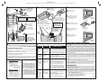
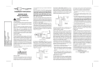
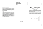
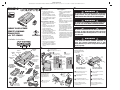
PRINTER’S INSTRUCTIONS:
INSTR,INSTL,GD00Z-4 - P/N: 236956 BX2 - INK: BLACK - MATERIAL: 20 LB. MEAD BOND - SIZE: 11.000” X 8.500” - TOL. +/-.125" - SCALE: 1-1 - FOLDING: 2-FOLD ALTERNATE - SIDE 1 OF 2
➊ PRODUCT DESCRIPTION
GD00Z-4
GD00Z-4 Overview
• A garage door opener remote
command transceiver with built-in
Z-Wave technology.
• Allows remote operation of a garage
door opener using Z-Wave controllers.
• Acts as a Z-Wave repeater to improve
communications within the Z-Wave
mesh network.
GD00Z-4 Summary of Operation
• GD00Z-4 connects to the garage door
opener’s pushbutton wall console
terminals.
• A wireless tilt sensor mounts on the
garage door and reports the door’s
position to the GD00Z-4.
• GD00Z-4 responds to Z-Wave
commands from Z-Wave controllers to
open or close the garage door.
• A warning indicator light flashes and
a beeper sounds for 5 seconds before
the door begins to move.
• If the door does not completely
open or close, a second open or
close command can be sent after
30 seconds.
• If the door does not completely open
or close after the second attempt,
the GD00Z-4 operation is suspended
until a local garage door pushbutton is
activated.
GARAGE DOOR OPENER
REMOTE COMMAND
TRANSCEIVER
with TILT SENSOR
Installation Instructions
➌ PRODUCT COMPONENTS
POWER
INPUT
JACK
STATUS
INDICATOR
GD00Z-4
WARNING
LIGHT
• Z-Wave® is a registered trademark
of Sigma Designs Inc. and/or its
subsidiaries.
• Z-Wave is an Interoperable two-way RF
mesh networking technology designed
for use with a Z-Wave gateway/
controller and other Z-Wave enabled
devices.
• Replication is the process of copying or
transferring your Z-Wave network from
one controller to another.
• This is a Security enabled Z-Wave
product and must be used with a
Security enabled Z-Wave controller
in order to fully utilize this product. As
such, this device will not respond to
Basic CC commands.
• ASSOCIATION: The GD00Z-4 supports
1 Group with 1 Node. Group 1 must be
assigned the Node ID of the controller
to which unsolicited notifications from
the GD00Z-4 will be sent. The Z-Wave
controller should set this association
automatically after inclusion.
➍ TILT SENSOR INSTALLATION AND BATTERY
1
WIRE
TIES
Attach the mounting plate
to the top panel of the door
Snap the sensor onto
the mounting plate
ARROWS ON PLATE
& SENSOR POINT UP
TILT
SENSOR
POWER
SUPPLY
POWER
SUPPLY
Use double sided tape or
the two mounting screws supplied
(drill 1/16" pilot holes if required)
The system will notify you
when the battery is low,
replace the battery with
a type CR2032 coin cell
1
SCREWS AND
MOUNTING TAPE
FOR TILT SENSOR
WALL
OUTLET
GD00Z-4
LINK
BUTTON
POWER
INPUT
JACK
POST ON
BOTTOM
POWER
SUPPLY
RETAINING
BRACKET
SCREW FOR
POWER SUPPLY
BRACKET
WARNING
"UP"
ARROWS
LOW BATTERY REPLACEMENT
SCREW AND
MOUNTING HARDWARE
FOR ADJUSTABLE
BRACKET
WARNING
The Remote Command Transceiver must be mounted in
the garage, in sight of the garage door, where the visual
and audible movement warning indicators can be clearly
seen and heard.
Note: Plug in the GD00Z-4
near your Z-Wave Controller
for these steps
3
MOUNTING SCREWS
AND ANCHORS
FOR GD00Z-4
OPTIONAL
ADJUSTABLE
GD00Z-4 MOUNTING
BRACKET
WARNING
This system can be installed on sectional type (roll up) doors
only per (UL-325). DO NOT INSTALL ON ONE-PIECE DOORS!
➎ PAIRING (INCLUDING) WITH THE SYSTEM
To activate the tilt sensor,
remove the battery protection pull strip
LINK
BUTTON
WARNING
This operator system is equipped with an unattended
operation feature. This door could move unexpectedly.
NO ONE SHOULD CROSS THE PATH OF A MOVING DOOR!
Do not install the Remote Command Transceiver on
garage door operators manufactured prior to 1993
(models without an operational safety beam entrapment
detection system).
2
CONNECTION
WIRES
➋ SAFETY NOTES
Z-Wave Information
2
PLUS SIDE UP !!!
Insert the
battery
into the
transmitter
TO INCLUDE THE GD00Z-4
INTO YOUR CONTROLLER
TO EXCLUDE THE GD00Z-4
FROM YOUR CONTROLLER
1 Place your Z-Wave Controller into
1 Place your Z-Wave Controller into
Discovery or Include mode.
2 Press and release the link button
2 Press and release the link button
3 Confirm that the GD00Z-4 was
3 Confirm that the GD00Z-4 was
Refer to your Z-Wave Controllers
instructions for additional information
on including devices.
Refer to your Z-Wave Controllers
instructions for additional information
on excluding devices.
on the GD00Z-4.
recognized by your Z-Wave Controller.
To open the case, twist
a small screwdriver
in case slot
SLOT
Exclude mode.
CR2032
on the GD00Z-4.
excluded by your Z-Wave Controller.
PRINTER’S INSTRUCTIONS:
INSTR,INSTL,GD00Z-4 - P/N: 236956 BX2 - INK: BLACK - MATERIAL: 20 LB. MEAD BOND - SIZE: 11.000” X 8.500” - TOL. +/-.125" - SCALE: 1-1 - FOLDING: 2-FOLD ALTERNATE - SIDE 2 OF 2
➏ GD00Z-4 MOUNTING
The GD00Z-4 typically
mounts on the ceiling
near the opener and
the power outlet
Tilt sensor
mounted on
the top panel
of the door
➐ GD00Z-4 CONNECTIONS
2
Plug the power cord
into the power input
jack on the GD00Z-4
THE GD00Z-4 WARNING
LAMP MUST BE VISIBLE IN
ALL DOOR POSITIONS
THE GD00Z-4 CAN ALSO BE ATTACHED TO THE OPENER'S
HARDWARE USING THE ADJUSTABLE MOUNTING BRACKET
Secure
bracket
with screw
1
Use the four screws
and anchors to mount
the GD00Z-4 above
the opener
1A
The optional adjustable
mounting bracket fits
3 ways on the GD00Z-4
garage door opener
3
1
Connect the GD00Z-4 connection
wires to the pushbutton wall console
terminals on the garage door opener.
The terminals may be named "PWC", "WC",
"PB", "PUSHBUTTON", or "RED and WHITE".
Terminal names and locations vary by model.
Remove the screw from 120 VAC
outlet faceplate. Secure the retaining
bracket to the faceplate with the provided
screw. Snap the power supply into the
bracket while plugging into the outlet.
DO NOT DISCONNECT
ANY WIRES CURRENTLY
CONNECTED TO THE
GARAGE DOOR OPENER !!!
use the garage door opener's
pushbutton to manually open
and close the door
STAY CLEAR
OF THE DOOR !!!
BEEP
BEEP
BEEP
3 Use your Z-Wave Controller to
activate your garage door opener
INDENT
INDENT
3/16" HOLES
FOR ANCHORS
The bracket snaps onto
indents on either side or
on the end of the GD00Z-4
Either wire can
connect to either
terminal
INDENT
2A
Use the bolts and nuts supplied
to attach the bracket to a secure
structure
GARAGE
DOOR
OPENER
GD00Z-4 Specifications
Power Supply: Input: 120 VAC, 0.8 A
Output: 12 VDC, 2 A
Operating Temperature: -4°—122° F (-20°—50° C)
Audible Alarm: 45 db @ 10 feet
Strobe: 360 Lumens
Communications: Z-Wave (908.4 MHz)
Mounting: Screws and anchors to
the ceiling, or bracket to the
opener’s hanging hardware
NOTICE TO USERS IN CALIFORNIA - CR COIN
CELL LITHIUM BATTERY INFORMATION: THIS
PRODUCT CONTAINS A CR COIN CELL LITHIUM
BATTERY WHICH CONTAINS PERCHLORATE
MATERIAL - SPECIAL HANDLING MAY APPLY - SEE
www.dtsc.ca.gov/hazardouswaste/perchlorate
KEEP AWAY FROM SMALL CHILDREN. IF BATTERY
IS SWALLOWED, PROMPTLY SEE A DOCTOR. DO
Type CR2032 Coin Cell Battery
NOT TRY TO RECHARGE THIS BATTERY. DISPOSAL
-4°—122° F (-20°—50° C)
OF USED BATTERIES MUST BE MADE IN
24 Months (typical)
ACCORDANCE WITH THE WASTE RECOVERY AND
Proprietary 345 MHz
RECYCLING REGULATIONS IN YOUR AREA.
100 feet line-of-sight to GD00Z-4
Double-sided tape or two
mounting screws
(Specifications subject to change without notice)
Tilt Sensor Specifications
4 The GD00Z-4 will beep and
flash for five seconds before
the door moves
FLASH
FLASH
FLASH
the door opener and open
or close the door
PU
SH
B
PU UTT
O
SH
BU N
TT
ON
OPERATION NOTES
➒
➓ TROUBLESHOOTING
1. The warning light will flash and the warning beeper will sound for five seconds
before the door opener is activated. STAY CLEAR OF THE DOOR, AND DOOR
OPENER. THEY ARE ABOUT TO MOVE!
2. If the door does not completely open or close after remote activation, the GD00Z-4
will allow user to try to operate the door one more time. If the second attempt fails,
the GD00Z-4 will go into lock-out mode. See Note #3.
3. If the GD00Z-4 is in lock-out mode and will not accept remote commands, activate
the door from the pushbutton wall console.
4. Once the GD00Z-4 has initiated the movement of the garage door, another
command cannot be sent for 30 seconds. This eliminates the chance of “bouncing”
the garage door and possibly damaging the garage door opener.
USE WIRE TIES TO SECURE
EXCESS WIRING CLEAR
OF ALL MOVING PARTS
OF THE GARAGE
DOOR AND OPENER
5 The GD00Z-4 will activate
BE SURE THE GD00Z-4
IS CLEAR OF ALL MOVING
PARTS OF THE GARAGE DOOR
AND THE WARNING LAMP IS
NOT OBSTRUCTED
Power Supply:
Operating Temperature:
Battery Life:
Communications:
Range:
Mounting to Garage Door:
1 Restore power to your
2 To synchronize the system,
! WARNING !
REMOVE POWER FROM THE
GARAGE DOOR OPENER
BEFORE CONTINUING
➑ SYSTEM OPERATION
PROBLEM
Unable to
include in
Z-Wave
network.
POSSIBLE
CAUSE
GD00Z-4 was
not properly
excluded from a
previous Z-Wave
network.
STAY CLEAR
OF THE DOOR !!!
NORTEK SECURITY & CONTROL LIMITED WARRANTY
CORRECTIVE ACTION
Reset the GD00Z-4 by pressing the LINK
button 5 times. A quick beep then a longer
beep indicates the reset. Use this procedure
only in the event that the network primary
controller is missing or otherwise inoperable.
The GD00Z-4
does not flash
or beep when
activated.
No power to the
GD00Z-4.
1. Make sure the power supply is plugged in
securely to a live outlet.
2. Make sure the power cord is plugged in
securely to the GD00Z-4.
The GD00Z-4
flashes and
beeps when
activated but
the door does
not move.
Obstruction
blocking the
door or incorrect
wiring.
1. Make sure that there are no obstacles
preventing the door from moving.
2. Make sure that the GD00Z-4 connection
wires are connected to the proper
terminals on the garage door opener.
Trace the wires from the garage door
opener’s pushbutton wall console to the
door opener. This is where the GD00Z-4
connection wires should be connected.
Garage door
opens or
closes, but the
status does
not change on
the Z-Wave
Controller.
The tilt sensor
signal is not
being received
by the GD00Z-4.
1. Make sure the tilt sensor is mounted
correctly on the garage door, with the
arrow pointing up.
2. Make sure the battery pull tab has been
removed from the tilt sensor.
3. Replace the battery in the tilt sensor.
What is Covered?
Nortek Security & Control (“NS&C”) warrants to consumers who purchase this product for personal, family or household
purposes new from NS&C directly or from an authorized NS&C dealer, that the product will be free from defects in materials
and workmanship for a period of (1) year from the date of purchase. This warranty only applies if the product is installed at a
residence in the 50 United States or District of Columbia, and only at the site of the original installation. It is not transferable.
This warranty is not extended to resellers. If a defect exists, NS&C will have you ship the defective part or product to us
and we will, at our option, either repair or replace it. This warranty does not cover defects or damages caused by improper
handling, maintenance, storage, installation, removal or re-installation, misuse, non-factory authorized modification or
alteration, use of incompatible accessories, electrical power problems or surges, impact by foreign objects, accident, fire,
acts of God, normal wear and tear or shipping damage other than a shipment from NS&C. Note that all NS&C products are
designed to be installed, removed and serviced by trained individuals or professionals. Keep your original sales receipt as
it will be required to obtain warranty service.This warranty shall not be extended or restarted upon receipt of any repaired
or replacement part or product under this warranty. No person is authorized to extend or otherwise modify this warranty.
How do I Obtain Warranty Service?
To obtain warranty service, email our Returns Department at [email protected]. Include your name, address, telephone
number, the model number of your product, a copy of your original sales receipt, and a description of the problem. Unless we
need to discuss the situation further with you, you will be emailed a Return Authorization Number and shipping instructions.
If we need to discuss the situation further with you, we will call or email you. NS&C may require troubleshooting on installed
product before a Return Authorization Number is issued. Anything shipped to us without a Return Authorization Number
will be automatically returned unopened. You are responsible for the charges for shipment to us, unless you are a California
resident.
Limitations
THE DURATION OF ANY IMPLIED WARRANTY, INCLUDING THE WARRANTIES OF MERCHANTABILITY AND FITNESS FOR A
PARTICULAR PURPOSE, SHALL NOT EXCEED THE WARRANTY PERIOD PROVIDED HEREIN.
Some states do not allow limitations on how long an implied warranty lasts, so the above limitation may not apply to you.
NS&C SHALL NOT BE LIABLE FOR ANY INCIDENTAL OR CONSEQUENTIAL DAMAGES RESULTING FROM THE BREACH OF
ANY WRITTEN OR IMPLIED WARRANTY.
Some states do not allow limitations on how long an implied warranty lasts, so the above limitation may not apply to you.This
warranty gives you specific legal rights, and you may also have other legal rights which vary from State to State.
REGULATORY NOTICES
Changes or modifications not expressly approved by the manufacturer could void the user’s authority to operate the equipment.
Les changements ou modifications non approuvés expressément par la partie responsable de la conformité pourrait annuler
l’autorité de l’utilisateur à faire fonctionner l’équipement.
This equipment has been tested and found to comply with the limits for Class B Digital Device, pursuant to Part 15 of the FCC
Rules. These limits are designed to provide reasonable protection against harmful interference in a residential installation. This
equipment generates and can radiate radio frequency energy and, if not installed and used in accordance with the instructions, may
cause harmful interference to radio communications. However, there is no guarantee that interference will not occur in a particular
installation. If this equipment does cause harmful interference to radio or television reception, which can be determined by turning the
equipment off and on, the user is encouraged to try to correct the interference by one or more of the following measures.
• Reorient or relocate the receiving antenna
• Increase the separation between the equipment and receiver
• Connect the equipment into an outlet on a circuit different from that to which the receiver is connected
• Consult the dealer or an experienced radio/TV technician for help
This Class B digital apparatus complies with Canadian ICES-003.
Cet appareil numérique de la classe B est conforme à la norme NMB-003 du Canada.
Copyright © 2015 Nortek Security & Control LLC
236956 BX2