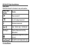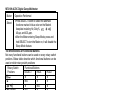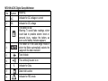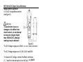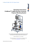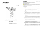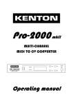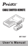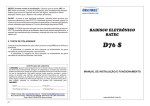
1
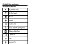
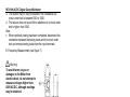
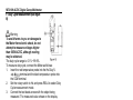
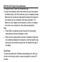
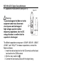
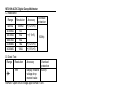
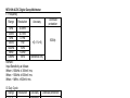
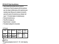
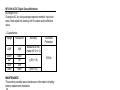
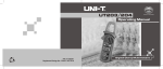
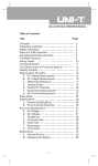
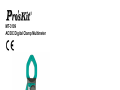
MT-3109 AC/DC Digital Clamp Multimeter 99 Washington Street Melrose, MA 02176 Phone 781-665-1400 Toll Free 1-800-517-8431 Visit us at www.TestEquipmentDepot.com User’s Manual st , 1 Edition 2011 ©2011 Copy Right by Prokit’s Industries Co., Ltd. MT-3109 AC/DC Digital Clamp Multimeter Overview This Operating Manual covers information on safety and cautions. Please read the relevant information carefully and observe all the Warnings and Notes strictly. Warning To avoid electric shock or personal injury, read the “Safety Information" and "Rules for Safe Operation" carefully before using the meter. Digital Clamp Multimeter Model (hereafter referred to as "the Meter") is 3 3/4 digits with steady operations, fashionable structure and highly reliable measuring instrument. The Meter uses large scale of integrated circuit with double integrated A/D converter as its core and has full range overload protection The Meter can not only measure AC/DC Voltage, AC/DC Current, Frequency, Duty Cycle, Resistance, Diodes, Continuity but also it has Data Hold, Sleep Mode and Relative Mode features. Unpacking Inspection Open the package case and take out the Meter. Check the following items carefully to see any missing or damaged part: Item Description Qty 1 User’s manual 1 piece 2 Test Lead 1 pair 3 Test Clip 1 pair 4 Carrying Bag 1 piece In the event you find any missing or damage, please contact your dealer immediately. Safety Information This Meter complies with the standards IEC61010: overvoltage category (CAT.II 600V) and double insulation. CAT. II: Local level, appliance, PORTABLE EQUIPMENT etc., with smaller transient over voltages than CAT.III CAT. III: Distribution level, fixed installation, with smaller transient over voltages than CAT. IV 1 MT-3109 AC/DC Digital Clamp Multimeter Use the Meter only as specified in this operating manual, otherwise the protection provided by the Meter may be impaired. In this manual, a Warning identifies conditions and actions that pose hazards to the user, or may damage the Meter or the equipment under test. A Note identifies the information that user should pay attention to International electrical symbols used on the Meter and in this Operating Manual are explained on page Rules for Safe Operation Warning To avoid possible electric shock or personal injury, and to avoid possible damage to the Meter or to the equipment under test, adhere to the following rules: Before using the Meter inspect the case. Do not use the Meter if it is damaged or the case (or part of the case) is removed. Look for cracks or missing plastic. Pay attention to the insulation around the connectors. Inspect the test leads for damaged insulation or exposed metal. Check the test leads for continuity. Replace damaged test leads with identical model number or electrical specifications before using the Meter. Do not apply more than the rated voltage, as marked on the Meter, between the terminals or between any terminal and grounding If the value to be measured is unknown, use the maximum measurement position and reduce the range step by step until a satisfactory reading is obtained When measurement has been completed, disconnect the connection between The test leads and the circuit under test, remove the testing leads away from the input terminals of the Meter and turn the Meter power off. The rotary switch should be placed in the right position and no any changeover of range shall be made during measurement is conducted to prevent damage of the Meter. 2 MT-3109 AC/DC Digital Clamp Multimeter Do not carry out the measurement when the Meter's back case and battery compartment are not closed to avoid electric shock. Do not input higher than 600V between the two Meter's input terminal to avoid electric shock and damages to the Meter. When the Meter working at an effective voltage over 60V in DC or 30V rms in AC, special care should be taken for there is danger of electric shock. Use the proper terminals, function, and range for your measurements. Do not use or store the Meter in an environment of high temperature, humidity, explosive, inflammable and strong magnetic field. The performance of the Meter may deteriorate after dampened. When using the test leads, keep your fingers behind the finger guards. Disconnect circuit power and discharge all high-voltage capacitors before testing resistance, continuity and diode. Replace the battery as soon as the battery indicator appears. With a low battery, the Meter might produce false readings that can lead to electric shock and personal injury. When servicing the Meter, use only the same model number or identical electrical specifications replacement parts. When servicing the Meter, use only the same model number or identical electrical specifications replacement parts. The internal circuit of the Meter shall not be altered at will to avoid damage of the Meter and any accident. Soft cloth and mild detergent should be used to clean the surface of the Meter when servicing. No abrasive and solvent should be used to prevent the surface of the Meter from corrosion, damage and accident. The Meter is suitable for indoor use. Turn the Meter off when it is not in use and take out the battery when not using for a long time. Constantly check the battery as it may leak when it has been using for some time, Replace the battery as soon as leaking appears. A leaking battery will damage the Meter. 3 MT-3109 AC/DC Digital Clamp Multimeter International Electrical Symbols AC (Alternating Current) DC (Direct Current) AC or DC Grounding Double Insulated Warning. Refer to the Operating Manual Deficiency of Built-In Battery Continuity Test Diode Capacitance Test Fuse Conforms to Standards of European Union The Meter Structure (see figure 1) 1. Input Terminals figure.1 2. LCD Display 3. Functional Buttons 4. Rotary Switch 5. Trigger: press the lever to open the transformer jaw 6. Hand Guards: to protect user's hand from touching the dangerous area. 7. Transformer Jaw: designed to pick up the AC and DC current flowing through the conductor. It could transfer current to voltage. The tested conductor must vertically go through the Jaw center. 4 MT-3109 AC/DC Digital Clamp Multimeter Rotary Switch Below table indicated for information of rotary switch positions. Rotary Switch Function Position OFF Power is turned off V AC or DC voltage measurement Ω Resistance measurement : Diode test / Hz / Duty % 40A & 400A : Continuity test Frequency Measurement and Duty Measurement Capacitance test range from 40.OOnF to 1OO.OuF AC and DC current measurement range Functional Buttons Below table for information of functional button operations. Operation Performed Button ● Press HOLD to enter the Hold mode in any mode, HOLD the Meter beeps. ● Press HOLD again to exit the Hold mode, the Meter beeps. and Ω range: At ELA Press select manual ranging measurement mode. The Meter is default to auto ranging measurement mode. When the Meter is at manual ranging measurement mode, press to step down the range. range: At Press enter to the REL mode. It subtracts a stored value from the present measurement value and displays a result. At Hz/Duty% range: Press switch to between Hz measurement mode and Duty % measurement mode. 5 MT-3109 AC/DC Digital Clamp Multimeter Button Select Operation Performed Press SELECT button to select the alternate functions marked in blue color on the Meter's , , faceplate including Hz, Duty%, , and 400 . 40 After the Meter entering Sleep Mode, press and hold SELECT to turn the Meter on, it will disable the Sleep Mode feature. The Effectiveness of Functional Buttons Not every functional buttons can be used on every rotary switch positions. Below table describe which functional buttons can be used on which rotary switch positions Rotary Switch Functional Buttons Positions SELECT RELA HOLD ● ● ● Ω N/A ● ● / ● N/A ● Hz / Duty% N/A ● ● 40 ● ● ● 400 ● ● ● N/A ● ● Display Symbols (see figure 2) 6 MT-3109 AC/DC Digital Clamp Multimeter Symbol Meaning 1 AC Indicator for AC voltage or current 2 DC Indicator for DC voltage The battery is low. Warning: To avoid false readings, which could lead to possible electric shock or personal injury, replace the battery as soon as the battery indicator appears. The Meter is in the auto range mode in which the Meter automatically selects the range with the best resolution. Test of diode No. 3 4 5 The continuity buzzer is on 6 7 % Data hold is active 8 Indicator for REL mode 9 10 Ω,KΩ, MΩ 11 Hz 12 A 13 Indicator for Duty. mV, V 14 Ω: Ohm. The unit3of resistance. kΩ: Kilohm. 1x10 or6 1000 ohms MΩ: Megohm. 1x10 or 1,000,000 ohms The unit of Frequency Amperes (amps). The unit of current. Volts. The unit of -3 voltage. mV: Millivolt. 1xl0 or 0.001 volts Indicates negative reading 15 TRMS Indicator for TRMS mode 16 F,nF,uF, 17 OL Farad. The unit of capacitance. The input value is too large for the selected range 7 MT-3109 AC/DC Digital Clamp Multimeter Measurement Operation A. DC/AC Voltage Measurement (see figure 3) Warning To avoid harms to you or damages to the Meter from electric shock, do not attempt to measure voltages higher than 600V AC/DC, although readings may be obtained The DC Voltage ranges are: 400mV, 4V, 40V, 400V and 600V. The AC Voltage ranges are: 4V, 40V, 400V and 600V. To measure DC voltage, connect the Meter as follows: VΩ (1) Insert the red test lead into the Hz Duty% terminal and the black test lead into the COM terminal. . DC measurement mode and (2) Set the rotary switch to auto ranging is a default. (3) Press SELECT to switch to AC measurement mode or press REL to switch to manual ranging measurement mode. (4) Connect the test leads across with the object being measured. The measured value shows on the display. Note A. When DC/AC voltage measurement has been completed, disconnect the connection between the testing leads and the circuit under test and remove testing leads from the input terminals. B. Measuring Resistance (see figure 4) 8 MT-3109 AC/DC Digital Clamp Multimeter Warning To avoid damages to the Meter or to the devices under test, disconnect circuit power and discharge all the high-voltage capacitors before measuring resistance. The resistance ranges are: 400Ω, 4kΩ, 40kΩ,400kΩ,4 MΩ and 40MΩ. To measure resistance, connect the Meter as follows: terminal 1. Insert the red test lead into the Hz Duty% and the black test lead into the COM terminal. 2. Set the rotary switch to Ω. Resistance measurement is default to auto range mode, press RELA to switch to manual ranging measurement mode. 3. Connect the test leads across with the object being measured. The measured value shows on the display. Note To obtain a more precise reading, you could remove the objects being tested from the circuit when measuring, When resistance measurement has been completed, disconnect the connection between the testing leads and the circuit under test and remove testing leads from the input terminals. C. Testing Diodes (see figure 5) Warning To avoid damages to the Meter or to the devices under test, disconnect circuit power and discharge all the high-voltage capacitors before testing diodes. Use the diode test to check diodes, transistors, and other semiconductor devices. The diode test sends a current through the semiconductor junction, then measure the 9 MT-3109 AC/DC Digital Clamp Multimeter voltage drop across the junction. A good silicon junction drops between 0.5V and 0.8V. To test the diode out of a circuit, connect the Meter as follows: 1. Insert the red test lead into the Hz Duty% -i))-H VQ terminal and the black test lead into the COM terminal. . Diode measurement mode is 2. Set the rotary switch to measurement a default or presses SELECT to select mode. 3. For forward voltage drop readings on any semiconductor component, place the red test lead on the component's anode and place the black test lead on the component's cathode. Note To obtain a more precise reading, you could remove the objects being tested from the circuit when measuring. When diode testing has been completed, disconnect the connection between the testing leads and the circuit under test and remove testing leads from the input terminals. D. Testing for Continuity (see figure 6) Warning To avoid damages to the Meter or to the devices under test, disconnect circuit power and discharge all the high-voltage capacitors before measuring continuity. To test for continuity, connect the Meter as follows: 1. Insert the red test lead into the Hz Duty% terminal and the black test lead into the COM terminal. and press SELECT button 2. Set the rotary switch to measurement mode. The buzzer sounds if to select the resistance of a circuit under test is less than 50Ω 10 MT-3109 AC/DC Digital Clamp Multimeter 3. The buzzer may or may not sounds if the resistance of a circuit under test is between 50Ω to 100Ω 4. The buzzer does not sound if the resistance of a circuit under test is higher than 100Ω Note When continuity testing has been completed, disconnect the connection between the testing leads and the circuit under test and remove testing leads from the input terminals. E. Frequency Measurement (see figure 7) Warning To avoid harms to you or damages to the Meter from electric shock, do not attempt to measure voltages higher than 600V AC/DC, although readings may be obtained. The resistance ranges are: 10Hz, 100Hz, 1kHz, 10kHz, 100kHz, 1MHz and 10MHz. To measure frequency, connect the Meter as follows: 1. Insert the red temperature probe into the Hz Duty% terminal and the black temperature probe into the COM terminal. 2. Set the rotary switch to Hz. 3. Connect the test leads across with the object being test. The measured value shows on the display. Note When frequency measurement has been completed, disconnect the connection between testing leads and the circuit under test, and remove testing leads away from the input terminals. 11 MT-3109 AC/DC Digital Clamp Multimeter F. Duty Cycle Measurement (see figure 8) Warning To avoid harms to you or damages to the Meter from electric shock, do not attempt to measure voltages higher than 600V AC/DC, although reading may be obtained. The duty cycle range is: 0.1% ~99.9%. To measure duty cycle, connect the Meter as follows: 1. Insert the red temperature probe into the Hz Duty% terminal and the black temperature probe into the COM terminal. 2. Set the rotary switch to Hz and press RELA to select Duty Cycle measurement mode. 3. Connect the test leads across with the object being measured. The measured value shows on the display. Note When duty cycle measurement has been completed, disconnect the connection between the testing leads and the circuit under test, and remove the testing leads away from the input terminals of the Meter. G DC/AC Current Measurement (see figure 9) The measurement ranges of current are: and 400.0 40.00 To measure current, do the following: or 1. Set the rotary switch to 40 . DC measurement mode is a 400 default. Presses SELECT to switch between DC and AC measurement mode. 2. Hold the Meter tight, don't release. The Hall components are very sensitive not only to the magnet but also to heat and machines reaction force. Any shock will cause the changing in reading in the short time. 12 2 MT-3109 AC/DC Digital Clamp Multimeter 3. Press the lever to open the transformer jaw. 4. Center the conductor within the transformer jaw, then release the Meter slowly until the transformer jaw is completely closed, Make sure the conductor to be tested is placed at the center of the transformer jaw, otherwise it will cause deviation. The Meter can only measure one conductor at a time, to measure more than one conductor at a time will cause deviation. Note Press RELA to subtracts a stored value from the present measurement value and displays a result. When current measurement has been completed, disconnect the connection between the conductor under test and the jaw, and remove the conductor away from the transformer jaw of the Meter. Sleep Mode To preserve battery life, the Meter automatically turns off if you do not turn the rotary switch or press any button for around 15 minutes. The Meter can be activated by turning the rotary switch or pressing the button based on 'The Effectiveness of Functional Buttons" on page 14. Press SELECT to activate the Meter will disable the Sleep Mode feature. The Meter beeps 5 times in about 1 minute before entering Sleep Mode and it will have a 1 long beep just before entering Sleep Mode. To disable the Sleep Mode function, press and hold SELECT button while turning on the Meter. 13 MT-3109 AC/DC Digital Clamp Multimeter H. Capacitance measurement (see figure 10) figure 10 Warming To avoid damage to the Meter or to the equipment under test, disconnect circuit power and discharge all high-voltage capacitors before measuring capacitance. Use the DC voltage function to confirm that the capacitor is discharged. The Meter's capacitance ranges arc: 40.00nF. 400.0nF, 4.000uF, 40.00uF, and 100.0μF. To measure capacitance, connect the Meter as follows: 1. Insert the red test lead into the HzV Ω terminal and the black test lead into the COM terminal. . 2. Set the rotary switch to 3. Connect the test leads across with the object being measured. The measured value shows on the display. Note For testing the capacitor with polarity, connect the red clip to anode & black clip to cathode instead of using test leads as mentioned above. To minimize the effect of capacitance stored in the test leads, the test lead should be as short as possible. To measure a small value of capacitance, use REL mode to remove the leads capacitance. Remaining voltage, insulated impedance & dielectric absorption from the capacitor may cause the measurement error. It takes a longer time when testing a high capacitor value, the testing time is around 15 seconds in 100uF range. The LCD displays OL indicating the tested capacitor is shorted or it exceeds the maximum range. When capacitance measurement has been completed, disconnect the connection between the testing leads and the circuit under test and remove the testing leads away from the input terminals of the Meter. 14 MT-3109 AC/DC Digital Clamp Multimeter Specifications A. General Specifications: Maximum Voltage between any Terminals and grounding: Refer to different range input protection voltage. Display: 3 3/4 digits LCD display, Maximum display 3999 Polarity: Automatically display. Overloading: Display OL or -OL Battery Deficiency: Display Measurement Speed: Updates 3 times/second. Measurement Deviation: The conductor being measured is not placed in the center of the jaw during AC/DC current measurement, it will cause extra +1 % deviation based on the stated accuracy. Max. Jaw Size: 30mm diameter. Projected Max. Current conductor size: 30mm diameter. Electro-Magnetic: When carrying out measurement near the electro-magnetic, it may cause unstable or wrong reading. Power: 3x1.5V battery ( AAA) (not included) Battery Life: typically 150hours (alkaline battery) Sleep Mode (can be disabled) Dimensions (H x W x 1): 203mm x 68mm x 33mm Weight: Approximate 235g (battery included) B. Environmental Requirements The Meter is suitable for indoor use. Altitude: Operating: 2000m Storage: 1OOOOm Safety/ Compliances: IEC 61010 CAT.II 600V over voltage and double insulation standard. Temperature and humidity: Operating: O℃~30℃(~ 85%R.H); 30℃~40℃ (~ 75%R.H); 40℃~50℃ (~ 45%R.H); Storage: -20℃~+60℃ (~ 85%R.H) 15 MT-3109 AC/DC Digital Clamp Multimeter Accurate Specifications Accuracy: +(a% reading + b digits). Operating temperature: 23℃±5℃ Relative humidity: ( 85%R.H) Temperature coefficient: 0.1x (specified accuracy)1℃ A. DC Voltage Range Resolution Accuracy 400.0mV 0.1mV +(1 %+3) 4.000V 1mV 40.00V 10mV 400.0V 100mV 600V 1V +(1 %+1) Overload protection 600V DC/AC + (1 %+5) Remarks: Input impedance: 10MΩ B_ AC Voltage Range Resolution Accuracy Overload protection 4.000V 1mV + (1.2%+5) 40.00V 10mV 600V DC/AC 400.0V 100mV 600V 1V +( 1 .5 %+5) Remarks: ●Input impedance: 10MΩ// less than 100pF ● Frequency response: 40Hz-400Hz. ● Change to AC: Change to AC by using average response method. Input sine wave, then adjust the reading until it is same as the effective value. 16 MT-3109 AC/DC Digital Clamp Multimeter C. Resistance Range Resolution Accuracy 400.0Ω 4.000kΩ 40.00kΩ 400.0kΩ 4.000MΩ 40.00MΩ 100mΩ 1Ω 10Ω 10Ω 1kΩ 10kΩ +(1.2%+5) D. Diode Test Range Resolution +(1 %+5) Overload protection 600Vp +(1.2%+5) +(1.5%+5) Accuracy 1mV Overload protection 600Vp Display forward voltage drop nearest value Remark: Open circuit voltage approximate 1.48V. E. Continuity Test Range resolution 100mΩ accuracy Around≤50Ω The buzzer beeps Overload protection 600Vp Remark: Open circuit voltage approximate 0.45V. The buzzer may or may not beeps when the resistance of a circuit under test is between 50Ω~1OOΩ The buzzer will not beep when the resistance of a circuit under test is > 1OOQ. 17 MT-3109 AC/DC Digital Clamp Multimeter F. Frequency Range Resolution Overload protection Accuracy 10Hz 0.00Hz 100Hz 0.01Hz 1kHz 0.1Hz +(0.1 %+5) 10kHz 1Hz 100kHz 10Hz 1MHz 100Hz 10MHz 1kHz reference only Remark: Input Sensitivity as follows: When ≤ 100kHz: ≥ 300mV rms; When > 100kHz: ≥ 600mV rms When > 1MHz: ≥ 800mV rms G. Duty Cycle Range Resolution 0.1 % 0.1 % ~99.9% H. DC Current Range Resolution 40.00A 0.01A 400.0A 0.1A Accuracy reference only Accuracy +(2.5%+5) +(2.5%+3) 600Vp Overload protection 600Vp Overload protection 400A DC/AC Warning The operating temperature must be 0℃~40℃ when measuring current. Remark: If the reading is positive, the current direction is from bottom to up. See figure 10, the front case face up while the bottom case face down. Hold the Meter tight, do now release. The hall components are very sensitive not only to the magnet but also to heat and machines reaction force. Any shock will cause the changing in reading in the short time. Follow the below procedure to measure current will be more precise: 18 MT-3109 AC/DC Digital Clamp Multimeter Hold the Meter tight and press the lever to open the transformer jaw. Center the conductor within the transformer jaws, then release the Meter slowly until the transformer jaw is completely closed. Make sure the conductor to be tested is placed at the center of the transformer jaw, otherwise it will cause +1 .0% deviation based on the stated accuracy. Remove the transformer jaw. Press RELA to display zero. Repeat the above 1. procedure. The obtained reading will be more precise. l. AC Current Range Resolu -tion 40.00A 0.01A 400.0A 0.1A Accuracy +(3%+8) +(3%+5) Frequency Response 50Hz ~ 60Hz Overload protection 400A DC/AC Warning The operating temperature must be O℃ ~40℃ when measuring current. Remark: It may have 10 digits or less unstable or wrong digits, it will not affect measurement result. Hold the Meter tight, do now release. The Hall components are very sensitive not only to the magnet but also to heat and machines reaction force. Any shock will cause the changing in reading in the short time. Follow the below procedure to measure current will be more precise: 1. Hold the Meter tight and press the lever to open the transformer jaw. Center the conductor within the transformer jaws, then release the Meter slowly until the transformer jaw is completely closed. Make sure the conductor to be tested is placed at the center of the transformer jaw, otherwise it will cause +1.0% deviation based on the stated accuracy. 2. Remove the transformer jaw. 3. Press RELA to display zero. 4. Repeat the above 1. procedure. 5. The obtained reading will be more precise. 19 MT-3109 AC/DC Digital Clamp Multimeter ●Change to AC: Change to AC by using average response method. Input sine wave, then adjust the reading until it is same as the effective value. J. Capacitance Resolution Range 40nF 10pF 400nF 4uF 40uF 100uF 100pF 1nF 10nF 100nF Accuracy Overload Protection Measure at REL mode ±(5 %+1 0) ±(5%+1 0) 600Vp ±(6%+10) MAINTENANCE This section provides basic maintenance information including battery replacement instruction. Warning Do not attempt to repair or service your Meter unless you are qualified to do so and have the relevant calibration, performance test, and service information To avoid electrical shock or damage to the Meter, do not get water inside the case. A. General Service Periodically wipe the case with a damp cloth and mild detergent. Do not use abrasives or solvents. To clean the terminals with cotton bar with detergent, as dirt or moisture in the terminals can affect readings. Turn the Meter power off when it is not in use. Take out the battery when it is not using for a long time. Do not use or store the Meter in a place of humidity, high temperature, explosive, inflammable and strong magnetic field. 20 MT-3109 AC/DC Digital Clamp Multimeter B. Replacing the Battery (see figure 11) Warning To avoid false readings, which could lead to possible electric shock or personal injury, replace the battery as soon as the " appears. Make sure the transformer jaw battery indicator " and the test leads are disconnected from the circuit being tested before opening the case bottom. To replace the battery: 1. Turn the Meter off and remove all the figure 11 connections from the input terminals 2. Turn the Meter's front case down. 3. Remove the screw from the battery compartment, and separate the battery compartment from the case bottom 4. Take out the old battery and replace with a new 9V battery 5. Rejoin the case bottom and the battery compartment, and reinstall the screw. ** END ** This operating manual is subject to change without notice. 21 MT-3109 AC/DC Digital Clamp Multimeter ©2011 Prokit’s Industries Co., LTD. All rights reserved 2011001(T) 35