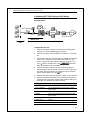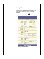
1
Multi-Mode ADSL Ethernet Router User’s Manual SSABR-B/SSABR-BU SSABR-B/SSABR-BU ADSL Ethernet Router User’s Guide July. 2003 2 SSABR-B/SSABR-BU ADSL Ethernet Router User’s Guide Copyright All rights reserved. No part of this document may be reproduced in any form or by any means without written permission from the product manufacturer. Changes are periodically made to the information in this document. They will be incorporated in subsequent editions. The product manufacturer may take improvement and/or changes in the product described in this document at any time. iii SSABR-B/SSABR-BU ADSL Ethernet Router User’s Guide FCC compliance This equipment complies with Part 68 of the FCC Rules. On this equipment is a label that contains, among other information, the FCC registration number and Ringer Equivalence Number (REN) for this equipment. You must upon request, provide this information to your telephone company. If your telephone equipment causes harm to the telephone network, the Telephone Company may discontinue your service temporarily. If possible, they will notify in advance. But, if advance notice isn’t practical, you will be notified as soon as possible. You will be informed of your right to file a complaint with the FCC. Your telephone company may make changes in its facilities, equipment, operations, or procedures that could affect proper operation of your equipment. If they do, you will be notified in advance to give you an opportunity to maintain uninterrupted telephone service. The FCC prohibits this equipment to be connected to party lines or coin-telephone service. In the event that this equipment should fail to operate properly, disconnect the equipment from the phone line to determine if it is causing the problem. If the problem is with the equipment, discontinue use and contact your dealer or vendor. DOC compliance information NOTICE: The Canadian Department of Communications label identifies certified equipment. This certification means that the equipment meets certain telecommunications network protective, operational and safety requirements. The Department does not guarantee the equipment will operate to the user’s satisfaction. Before installing this equipment, users ensure that it is permissible to be connected to the facilities of the local Telecommunications Company. The equipment must also be installed using an acceptable method of connection. The customer should be aware that compliance with the above conditions might not prevent degradation of service in some situations. Repairs to certified equipment should be made by an authorized Canadian maintenance facility designated by the supplier. Any repairs or alterations made by the user to this equipment, or equipment malfunctions, may give the telecommunications company cause to request the user to disconnect the equipment. Users should ensure for their own protection that the electrical ground connections of the power utility, telephone lines and internal metallic water pipe system, if present, are connected together. This precaution may be particularly important in rural areas. CAUTION: Users should not attempt to make such connections themselves, but should contact the appropriate electric inspection authority, or electrician, as appropriate. NOTICE: The Load Number (LN) assigned to each terminal device denotes the percentage of the total load to be connected to a telephone loop which is used by the device, to prevent overloading. iv SSABR-B/SSABR-BU ADSL Ethernet Router User’s Guide The termination on a loop may consist of any combination of devices subject only to the requirement that the sum of the Load Numbers of all the devices does not exceed 100. European CTR 21 compliance The equipment has been approved in accordance with Council Decision 98/482/EC for pan-European single terminal connection to the public switched telephone network (PSTN). However, due to differences between the individual PSTNs provided in different countries, the approval does not, of itself, give an unconditional assurance of successful operation on every PSTN network termination point. In the event of problem, you should contact your equipment supplier in the first instance. Note: The manufacturer should ensure that the vendor and user of the equipment is clearly informed of the above information by means of package and/or user manuals of the forms of user instructions. v SSABR-B/SSABR-BU ADSL Ethernet Router User’s Guide Table of Contents 1 INTRODUCTION.................................................................................................... 1 FEATURES ............................................................................................................................................. 1 SYSTEM REQUIREMENTS ..................................................................................................................... 2 USING THIS DOCUMENT....................................................................................................................... 2 What’s covered in this document?...................................................................................... 2 Notational conventions........................................................................................................ 2 Typographical conventions................................................................................................. 2 Special messages ................................................................................................................. 3 CUSTOMER AND TECHNICAL SUPPORT ............................................................................................... 3 2 GETTING TO KNOW THE ADSL ETHERNET ROUTER .............................. 5 PARTS CHECK....................................................................................................................................... 5 FRONT PANEL....................................................................................................................................... 5 REAR PANEL......................................................................................................................................... 5 3 QUICK START ........................................................................................................ 7 PART 1 — CONNECTING THE HARDWARE ......................................................................................... 7 Step 1. Connect the ADSL cable and optional telephone. ................................................ 8 Step 2. Connect the Ethernet cable..................................................................................... 8 Step 3. Attach the power connector.................................................................................... 8 Step 4. Turn on the ADSL Router and power up your systems......................................... 8 PART 2 — CONFIGURING YOUR COMPUTERS.................................................................................... 9 Before you begin .................................................................................................................. 9 Windows 95, 98 PCs:....................................................................................................... 9 Windows NT 4.0 workstations:.........................................................................................10 Windows 2000 PCs: ..........................................................................................................11 Windows Me PCs...............................................................................................................12 Assigning static Internet information to your PCs ..........................................................13 PART 3 — CONFIGURING THE ADSL ROUTER ................................................................................14 TESTING YOUR SETUP .......................................................................................................................15 4 GETTING STARTED WITH THE CONFIGURATION MANAGER ............ 17 ACCESSING THE CONFIGURATION MANAGER ..................................................................................17 FUNCTIONAL LAYOUT .......................................................................................................................19 THE HOME TAB AND SYSTEM VIEW TABLE .....................................................................................20 CHANGING THE SYSTEM DATE AND TIME ........................................................................................22 vi SSABR-B/SSABR-BU ADSL Ethernet Router User’s Guide CHANGING THE SYSTEM DATE AND TIME ........................................................................................22 CHANGING YOUR LOGIN PASSWORD ...............................................................................................23 COMMITTING YOUR CHANGES AND REBOOTING THE DEVICE .......................................................25 Committing your changes .................................................................................................25 Rebooting the device using Configuration Manager ......................................................26 CONFIGURING RFC 1483 BRIDGE OF ADSL ROUTER ...................................................................27 Network Outline.................................................................................................................27 Configuration Process: .....................................................................................................27 CONFIGURING RFC 2516 PPPOE ROUTING OF ADSL ROUTER ....................................................29 Network Outline.................................................................................................................29 Configuration Process: .....................................................................................................29 CONFIGURING RFC 2364 PPPOA ROUTING OF ADSL ROUTER ....................................................31 Network Outline.................................................................................................................31 Configuration Process: .....................................................................................................31 CONFIGURING RFC 1483 ROUTING OF ADSL ROUTER..................................................................33 Network Outline.................................................................................................................33 Configuration Process: .....................................................................................................33 CONFIGURING RFC 1577 ROUTING OF ADSL ROUTER..................................................................35 Network Outline.................................................................................................................35 Configuration Process: .....................................................................................................35 5 SETTING THE LAN IP ADDRESS..................................................................... 37 CONFIGURING THE LAN IP ADDRESS ..............................................................................................37 CONFIGURING THE LAN IP ADDRESS ..............................................................................................38 6 VIEWING SYSTEM IP INFORMATION AND PERFORMANCE STATISTICS .......................................................................................................... 43 VIEWING THE ADSL ROUTER’S IP ADDRESSES...............................................................................43 VIEWING IP GLOBAL STATISTICS .....................................................................................................44 7 CONFIGURING DYNAMIC HOST CONFIGURATION PROTOCOL ........ 45 OVERVIEW OF DHCP.........................................................................................................................45 What is DHCP? .................................................................................................................45 Why use DHCP?................................................................................................................45 ADSL Router DHCP modes..............................................................................................46 CONFIGURING DHCP SERVER ..........................................................................................................47 Viewing, modifying, and deleting address pools, and excluding IP addresses from a pool.....................................................................................................................................................50 Viewing current DHCP address assignments .................................................................51 CONFIGURING DHCP RELAY............................................................................................................52 SETTING THE DHCP MODE...............................................................................................................53 8 CONFIGURING NETWORK ADDRESS TRANSLATION............................. 55 OVERVIEW OF NAT ...........................................................................................................................55 YOUR DEFAULT NAT SETUP ............................................................................................................56 vii SSABR-B/SSABR-BU ADSL Ethernet Router User’s Guide VIEWING NAT GLOBAL SETTINGS AND STATISTICS ......................................................................57 VIEWING NAT RULES AND RULE STATISTICS .................................................................................57 VIEWING CURRENT NAT TRANSLATIONS .......................................................................................57 ADDING NAT RULES.........................................................................................................................57 The napt rule: Translating between private and public IP addresses ...........................57 The RDR rule: Allowing external access to a LAN computer ........................................57 The basic rule: Performing 1:1 translations....................................................................57 The filter rule: Configuring a basic rule with additional criteria ..................................57 The bimap rule: Performing two-way translations .........................................................57 The pass rule: Allowing specific addresses to pass through untranslated ....................57 9 CONFIGURING DNS SERVER ADDRESSES .................................................. 57 ABOUT DNS.......................................................................................................................................57 ASSIGNING DNS ADDRESSES ...........................................................................................................57 CONFIGURING DNS RELAY ..............................................................................................................57 10 CONFIGURING IP ROUTES .................................................................. 57 OVERVIEW OF IP ROUTES .................................................................................................................57 Comparing IP routing to telephone switching.................................................................57 Hops and gateways............................................................................................................57 Using IP routes to define default gateways......................................................................57 Do I need to define IP routes? ..........................................................................................57 VIEWING THE IP ROUTING TABLE ....................................................................................................57 ADDING IP ROUTES ...........................................................................................................................57 11 CONFIGURING THE ROUTING INFORMATION PROTOCOL..... 57 RIP OVERVIEW ..................................................................................................................................57 When should you configure RIP? .....................................................................................57 CONFIGURING THE ADSL ROUTER’S INTERFACES WITH RIP.........................................................57 VIEWING RIP STATISTICS..................................................................................................................57 12 CONFIGURING THE ATM VCC............................................................ 57 VIEWING YOUR ATM VC SETUP .....................................................................................................57 ADDING ATM VCCS.........................................................................................................................57 MODIFYING ATM VCCS ..................................................................................................................57 13 CONFIGURING PPP INTERFACES...................................................... 57 VIEWING YOUR CURRENT PPP CONFIGURATION............................................................................57 VIEWING PPP INTERFACE DETAILS ..................................................................................................57 ADDING A PPP INTERFACE DEFINITION ...........................................................................................57 MODIFYING AND DELETING PPP INTERFACES.................................................................................57 viii SSABR-B/SSABR-BU ADSL Ethernet Router User’s Guide 14 CONFIGURING EOA INTERFACES .................................................... 57 OVERVIEW OF EOA ...........................................................................................................................57 VIEWING YOUR EOA SETUP.............................................................................................................57 ADDING EOA INTERFACES ...............................................................................................................57 15 CONFIGURING IPOA INTERFACES ................................................... 57 VIEWING YOUR IPOA INTERFACE SETUP.........................................................................................57 ADDING IPOA INTERFACES ...............................................................................................................57 16 CONFIGURING BRIDGING................................................................... 57 OVERVIEW OF BRIDGES .....................................................................................................................57 USING THE BRIDGING FEATURE ........................................................................................................57 DEFINING BRIDGE INTERFACES.........................................................................................................57 SYSTEM MODE ...................................................................................................................................57 DELETING A BRIDGE INTERFACE ......................................................................................................57 17 CONFIGURING FIREWALL SETTINGS ............................................. 57 CONFIGURING GLOBAL FIREWALL SETTINGS ..................................................................................57 MANAGING THE BLACK LIST ............................................................................................................57 18 CONFIGURING IP FILTERS.................................................................. 57 OVERVIEW ..........................................................................................................................................57 VIEWING YOUR IP FILTER CONFIGURATION....................................................................................57 CONFIGURING IP FILTER GLOBAL SETTINGS ...................................................................................57 CREATING IP FILTER RULES .............................................................................................................57 IP FILTER RULE EXAMPLES ................................................................................................................57 VIEWING IP FILTER STATISTICS ........................................................................................................57 MANAGING CURRENT IP FILTER SESSIONS......................................................................................57 19 20 VIEWING DSL PARAMETERS.............................................................. 57 VIEWING SYSTEM ALARMS ............................................................... 57 VIEWING THE ALARM TABLE ............................................................................................................57 DISPLAYING THE ALARM MONITOR IN A SEPARATE WINDOW .......................................................57 ix SSABR-B/SSABR-BU ADSL Ethernet Router User’s Guide A IP ADDRESSES, NETWORK MASKS, AND SUBNETS ................................. 57 IP ADDRESSES ....................................................................................................................................57 Structure of an IP address.................................................................................................57 Network classes..................................................................................................................57 SUBNET MASKS ..................................................................................................................................57 B BINARY NUMBERS ............................................................................................. 57 BINARY NUMBERS .............................................................................................................................57 Bits and bytes .....................................................................................................................57 C TROUBLESHOOTING ........................................................................................ 57 DIAGNOSING PROBLEM USING IP UTILITIES ....................................................................................57 ping .....................................................................................................................................57 nslookup .............................................................................................................................57 D x GLOSSARY............................................................................................................ 57 1 Introduction Congratulations on becoming the owner of the ADSL Ethernet Router. Your LAN (local area network) will now be able to access the Internet using your high-speed ADSL connection. This User Guide will show you how to install and set up your ADSL Ethernet Router. Features ! External ADSL Router for high-speed Internet access ! 10/100Base-T Ethernet router to provide Internet connectivity to all computers on your LAN ! Network address translation (NAT) and IP filtering functions to provide firewall protection for your computers and LAN ! Network configuration through DHCP ! User friendly web based configuration 1 SSABR-B/SSABR-BU ADSL Ethernet Router User’s Guide System Requirements In order to use your ADSL Ethernet Router, you must have the following: ! ADSL service up and running on your telephone line ! One or more computers equipped with Ethernet 10BaseT/100Base-T network interface card (NIC) ! An Ethernet hub/switch with an uplink port, if you want to connect your ADSL Ethernet Router to more than one computer ! A web browser such as Internet Explorer v5.0 or later, or Netscape v4.7 or later installed in your PC for system configuration. Using this Document What’s covered in this document? This document provides explanations and procedures to assist you when using the ADSL Ethernet Router with a typical small home or office network. Furthermore, this ADSL Ethernet Router can support many advanced or specialized network and ADSL configurations; contact your ADSL service provider for configuration information if not covered in this document. Notational conventions ! Acronyms are defined the first time they appear in text and in the glossary (Appendix D). ! The terms LAN and network are used interchangeably to refer to a group of Ethernet-connected computers at one site. Typographical conventions ! Italics are used to identify terms that are defined in the glossary (Appendix D). ! Bolded text is used for items you select from menus and drop-down lists, and to identify field labels you view onscreen. 2 SSABR-B/SSABR-BU ADSL Ethernet Router User’s Guide Special messages This document uses the following icons to call your attention to specific instructions or explanations. Note Definition Provides clarifying or non-essential information on the current topic. Explains terms or acronyms that may be unfamiliar to many readers. These terms are also included in the Glossary. Provides messages of high importance, including messages relating to personal safety or system integrity. WARNING Customer and Technical Support We are committed to providing our customers with reliable products and documentation, backed by excellent technical support. Before contacting us, please look in Appendix C “Troubleshooting” for a solution to your problem. You may find a solution in Appendix C “Troubleshooting”. If you cannot find a solution, collect your configuration information listed below before contacting our technical support. We can help you with your problem more effectively if you have completed the configuration information. Model number: Serial (MAC) number: Firmware version: PC configuration Network configuration Others information: 3 2 Getting to Know the ADSL Ethernet Router Parts Check In addition to this document, your ADSL Ethernet Router should arrive with the following: ! ! ! ! ! One ADSL Ethernet Router One power adapter One RJ-45 straight-through Ethernet cable One RJ-11 Telephone cable One RS-232C cable (optional) Front Panel The front panel LED indicators can briefly show you the status of your ADSL Ethernet Router. Label Function POWER On: Unit is powered on Off: Unit is powered off LINK On: ADSL link established and active Off: No ADSL link (XDSL) ACT (XDSL) LINK (LAN) 10/100M (LAN) Flashes when ADSL data activity occurs. May appear solid when data traffic is heavy. On: PC or LAN link established and active Off: No PC or LAN link Flashes when Ethernet data activity occurs. May appear solid when data traffic is heavy. On: Running 100Base-T Ethernet mode on LAN port Off: Running 10Base-T Ethernet mode on LAN port Rear Panel The rear panel contains the ports for the unit's data and power connections. Label Function DSL Connects the device to a telephone jack using the supplied cable LAN Connects the device to your PC's Ethernet port, or to the uplink port on your LAN's hub, using the cable provided Console The console port is a RS232C interface, which is used for Telco’s system configuration. 5 SSABR-B/SSABR-BU ADSL Ethernet Router User’s Guide 6 Label Function DC Connects to the supplied power adaptor DC cable On/Off Switches the unit on and off 3 Quick Start This Quick Start provides basic instructions for connecting the ADSL Router to a computer or LAN and to the Internet. ! Part 1 describes setting up the hardware. ! Part 2 describes how to configure Internet properties on your computer(s). ! Part 3 shows you how to configure basic settings on the ADSL Router to get your LAN connected to the Internet. This Quick Start assumes that you have already established ADSL service with your Internet service provider (ISP). These instructions provide a basic configuration that should be compatible with your home or small office network setup. Refer to the subsequent chapters for additional configuration instructions. Part 1 — Connecting the Hardware In Part 1, you connect the device to the phone jack, the power outlet, and your computer or network. WARNING Before you begin, turn the power off for all devices. These include your computer(s), your LAN hub/switch (if applicable), and the ADSL Router. Figure 1 illustrates the hardware connections. The layout of the ports on your device may vary from the layout shown. Refer to the steps that follow for specific instructions. 7 SSABR-B/SSABR-BU ADSL Ethernet Router User’s Guide ADSL Ethernet Router 3 RS-232C cable AC adapter 1 or Wall outlet Straight-through cable to Hub for LAN PCs . Wall jack 2 Straight-through cable to a PC Stand-alone computer Computer Computer Computer Figure 1. Overview of Hardware Connections Step 1. Connect the ADSL cable and optional telephone. Connect one end of the provided phone cable to the port labeled ADSL on the rear panel of the device. Connect the other end to your wall phone jack. Step 2. Connect the Ethernet cable. If you are connecting a LAN to the ADSL Ethernet router, attach one end of a provided Ethernet cable to a PC’s network interface card and the other to the Ethernet port on the ADSL Router. Step 3. Attach the power connector. Connect the AC power adapter to the PWR connector on the back of the device and plug in the adapter to a wall outlet or power strip. Step 4. Turn on the ADSL Router and power up your systems. Press the Power switch on the back panel of the device to the ON position. Turn on and boot up your computer(s) and any LAN devices such as hubs or switches. 8 SSABR-B/SSABR-BU ADSL Ethernet Router User’s Guide Part 2 — Configuring Your Computers Part 2 of the Quick Start provides instructions for configuring the Internet settings on your computers to work with the ADSL Ethernet Router. Before you begin By default, the ADSL Ethernet Router automatically assigns all required Internet settings to your PCs. You need only to configure the PCs to accept the information when it is assigned. Note In some cases, you may want to assign Internet information manually to some or all of your computers rather than allow the ADSL Ethernet Router to do so. See “Assigning static Internet information to your PCs ” on page 13 for instructions. These instructions assume that your PCs are already connected to a LAN through their network interface cards (NICs) and the appropriate Ethernet adapter software. Follow the instructions that correspond to the operating system installed on each PC. Windows 95, 98 PCs: First, check for the IP protocol and, if necessary, install it: 1. In the Windows task bar, click the Start button, point to Settings, and then click Control Panel. 2. Double-click the Network icon. The Network dialog box displays with a list of currently installed network components. If the list includes TCP/IP, and then the protocol has already been enabled. Skip to step 9. 3. If TCP/IP does not display as an installed component, click . The Select Network Component Type dialog box displays. 4. Select Protocol, and then click . The Select Network Protocol dialog box displays. 5. Click on Microsoft in the Manufacturers list box, and then click TCP/IP in the Network Protocols list box. 6. Click then click to return to the Network dialog box, and again. You may be prompted to install files from your Windows 95/98 installation CD. Follow the instructions to install the files. 9 SSABR-B/SSABR-BU ADSL Ethernet Router User’s Guide 7. Click to restart the PC and complete the TCP/IP installation. Next, configure the PCs to accept IP information assigned by the ADSL Router: 8. Open the Control Panel window, and then click the Network icon. 9. Select the network component labeled TCP/IP, and then . click If you have multiple TCP/IP listings, select the listing associated with your network card or adapter. 10. In the TCP/IP Properties dialog box, click the IP Address tab. 11. Click the radio button labeled Obtain an IP address automatically. 12. Click the DNS Configuration tab, and then click the radio button labeled Obtain an IP address automatically. twice to confirm and save your changes. 13. Click You will be prompted to restart Windows. . 14. Click Windows NT 4.0 workstations: First, check for the IP protocol and, if necessary, install it: 1. In the Windows NT task bar, click the Start button, point to Settings, and then click Control Panel. 2. In the Control Panel window, double click the Network icon. 3. In the Network dialog box, click the Protocols tab. The Protocols tab displays a list of currently installed network protocols. If the list includes TCP/IP, then the protocol has already been enabled. Skip to step 9. 4. If TCP/IP does not display as an installed component, click . 5. In the Select Network Protocol dialog box, select TCP/IP, and then click . You may be prompted to install files from your Windows NT installation CD or other media. Follow the instructions to install the files. After all files are installed, a window displays to inform you that a TCP/IP service called DHCP can be set up to dynamically assign IP information. to continue, and then click 6. Click prompted to restart your computer. 10 if SSABR-B/SSABR-BU ADSL Ethernet Router User’s Guide Next, configure the PCs to accept IP information assigned by the ADSL Router: 7. Open the Control Panel window, and then double-click the Network icon. 8. In the Network dialog box, click the Protocols tab. 9. In the Protocols tab, select TCP/IP, and then click . 10. In the Microsoft TCP/IP Properties dialog box, click the radio button labeled Obtain an IP address from a DHCP server. twice to confirm and save your changes, 11. Click and then close the Control Panel. Windows 2000 PCs: First, check for the IP protocol and, if necessary, install it: 1. In the Windows task bar, click the Start button, point to Settings, and then click Control Panel. 2. Double-click the Network and Dial-up Connections icon. 3. In the Network and Dial-up Connections window, right-click the Local Area Connection icon, and then select Properties. The Local Area Connection Properties dialog box displays with a list of currently installed network components. If the list includes Internet Protocol (TCP/IP), then the protocol has already been enabled. Skip to step 10. 4. If Internet Protocol (TCP/IP) does not display as an installed . component, click 5. In the Select Network Component Type dialog box, select . Protocol, and then click 6. Select Internet Protocol (TCP/IP) in the Network Protocols list, and then click . You may be prompted to install files from your Windows 2000 installation CD or other media. Follow the instructions to install the files. 7. If prompted, click the new settings. to restart your computer with Next, configure the PCs to accept IP information assigned by the ADSL Router: 8. In the Control Panel, double-click the Network and Dial-up Connections icon. 9. In Network and Dial-up Connections window, right-click the Local Area Connection icon, and then select Properties. 11 SSABR-B/SSABR-BU ADSL Ethernet Router User’s Guide 10. In the Local Area Connection Properties dialog box, select Internet Protocol (TCP/IP), and then click 11. In the Internet Protocol (TCP/IP) Properties dialog box, click the radio button labeled Obtain an IP address automatically. Also click the radio button labeled Obtain DNS server address automatically. twice to confirm and save your changes, 12. Click and then close the Control Panel. Windows Me PCs 1. In the Windows task bar, click the Start button, point to Settings, and then click Control Panel. 2. Double-click the Network and Dial-up Connections icon. 3. In the Network and Dial-up Connections window, right-click the Network icon, and then select Properties. The Network Properties dialog box displays with a list of currently installed network components. If the list includes Internet Protocol (TCP/IP), then the protocol has already been enabled. Skip to step 11. 4. If Internet Protocol (TCP/IP) does not display as an installed . component, click 5. In the Select Network Component Type dialog box, select . Protocol, and then click 6. Select Microsoft in the Manufacturers box. 7. Select Internet Protocol (TCP/IP) in the Network Protocols . list, and then click You may be prompted to install files from your Windows Me installation CD or other media. Follow the instructions to install the files. to restart your computer with 8. If prompted, click the new settings. Next, configure the PCs to accept IP information assigned by the ADSL Router: 9. In the Control Panel, double-click the Network and Dial-up Connections icon. 10. In Network and Dial-up Connections window, right-click the Network icon, and then select Properties. 11. In the Network Properties dialog box, select TCP/IP, and then click . 12. In the TCP/IP Settings dialog box, click the radio button labeled Server assigned IP address. Also click the radio button labeled Server assigned name server address. 12 . SSABR-B/SSABR-BU ADSL Ethernet Router User’s Guide 13. Click twice to confirm and save your changes, and then close the Control Panel. Assigning static Internet information to your PCs In some cases, you may want to assign Internet information to some or all of your PCs directly (often called “statically”), rather than allowing the ADSL Router to assign it. This option may be desirable (but not required) if: ! You have obtained one or more public IP addresses that you want to always associate with specific computers (for example, if you are using a computer as a public web server). ! You maintain different subnets on your LAN (subnets are described in Appendix 0). Before you begin, contact your ISP if you do not already have the following information: ! The IP address and subnet mask to be assigned to each PC to which you will be assigning static IP information. ! The IP address of the default gateway for your LAN. In most cases, this is the address assigned to the LAN port on the ADSL Router. By default, the LAN port is assigned this IP address: 192.168.7.1. (You can change this number, or another number can be assigned by your ISP. See Chapter 5 for more information.) ! The IP address of your ISP’s Domain Name System (DNS) server. On each PC to which you want to assign static information, follow the instructions on pages 9 through 12 relating only to checking for and/or installing the IP protocol. Once it is installed, continue to follow the instructions for displaying each of the Internet Protocol (TCP/IP) properties. Instead of enabling dynamic assignment of the IP addresses for the computer, DNS server and default gateway, click the radio buttons that enable you to enter the information manually. Note Your PCs must have IP addresses that place them in the same subnet as the ADSL Router’s LAN port. If you manually assign IP information to all your LAN PCs, you can follow the instructions in Chapter 5 to change the LAN port IP address accordingly. 13 SSABR-B/SSABR-BU ADSL Ethernet Router User’s Guide Part 3 — Configuring the ADSL Router The ADSL Ethernet Router is pre-configured with default settings for use with a typical home or small office network setup. Table 1 lists important default settings (other are described in the subsequent chapters). Verify that they meet the needs of your network, or follow the instructions to change them if necessary. If you are unfamiliar with these settings, try using the device without modification, or contact your ISP for assistance. Before modifying any settings, review Chapter 1 for general information about using the Configuration Manager program. We strongly recommend that you contact your ISP prior to changing the default configuration. Table 1. Default Settings Option Default Setting Explanation/Instructions The ADSL Ethernet Router configured to act as a bridging device between your LAN and your ISP. Bridges are devices that enable two or more networks to communicate as if they are two segments of the same physical LAN. See Chapter 17 for instructions on ATM Properties One ATM interface defined with these properties: Supports aal5 VPI = 0 VCI = 32 MUX type: LLC The VPI and VCI values determine the path of your connection to your ISP. Contact them to determine if these defaults need to be changed, and see Chapter 12 for additional instructions. DHCP (Dynamic Host Configuration Protocol) DHCP server disabled The ADSL Ethernet Router maintains a pool of 12 private IP addresses for dynamic assignment to your LAN computers . To use this service, you must have set up your computers to accept IP information dynamically, as described in Part 2 of the Quick Start. See Chapter 1 for an explanation of the DHCP service. NAT (Network Address Translation) napt rule disabled Your computers’ private IP addresses (see DHCP above) will be translated to your public IP address whenever they access the Internet. See Chapter 1 for a description of the NAT service. LAN Port IP Address Assigned static IP address: 192.168.7.1 This is the IP address of the LAN port on the device. The LAN port connects the device to your Ethernet network. Typically, you will not need to change this address. See Chapter 0 for instructions. ISP Connection Properties subnet mask: 255.255.255.0 14 changing settings. SSABR-B/SSABR-BU ADSL Ethernet Router User’s Guide Testing Your Setup The Quick Start process you just completed should enable any computer on your LAN to use the ADSL Ethernet Router’s ADSL connection to access the Internet. To test the connection, turn on the device, wait about 30 seconds, and then verify that its LEDs are illuminated as shown in Table 2. Table 2. LED Indicators This LED: POWER LINK (XDSL) ACT (XDSL) LINK (LAN) 10/100M (LAN) ...should be: Solid light to indicate that the device is turned on. If this light is not on, check the power cable attachment. Solid light to indicate that the device has successfully established a connection with your ISP. Flashing when the device is sending or receiving data from the Internet. It may be unlit, flashing, or appear solid depending on the current activity. Solid light to indicate that the device can communicate with your LAN. Flashing when the device is sending or receiving data from your LAN PCs or devices. It may be unlit, flashing, or appear solid depending on the current activity. Solid light to indicate that the LAN port of device is running 100Base-T Ethernet mode. Otherwise, it’s running 10Base-T Ethernet mode. If the LEDs illuminate as expected, test your Internet connection from a LAN computer: Open your web browser, and type the URL of any external website (such as http://www.yahoo.com). The LED labeled ACT (XDSL) should be blinking rapidly and may appear solid as the device connects to the site. If the LEDs do not illuminate as expected or the web page does not display: ! Ensure that the default settings shown on page 14 are appropriate for your network setup. ! See Appendix A, “Troubleshooting” for tips on correcting a variety of common problems. ! Contact your ISP customer support for assistance. 15 4 Getting Started with the Configuration Manager The ADSL Router includes preinstalled program called the Configuration Manager, which provides an interface to the software installed on the device. It enables you to configure the device settings to meet the needs of your network. You access it through your web browser from any PC connected to the ADSL Router via the LAN port. This chapter describes how to use the Configuration Manager. Note The ADSL Router may already be configured to provide Internet connectivity for your network. If it works properly with the preconfigured settings, then you may not need to use the Configuration Manager. Contact your ISP to determine which settings you may need to change, if any. Accessing the Configuration Manager The Configuration Manager program is preinstalled into memory on the ADSL Router. To access the program, you need the following: ! A PC or laptop connected to the LAN port on the device as described in the Quick Start chapter. ! An web browser installed on the PC. The program is designed to work best with Microsoft Internet Explorer® version 5.0, Netscape Navigator® version 4.7, or later versions. You can access the program from any computer connected to the ADSL Router via the LAN port. 1. From a LAN computer, configure the IP of your computer in the same subnet as ADSL Ethernet Router within. For example IP: 192.168.7.3, Subnet Mask: 255.255.255.0. Restart your computer if necessary.Open your web browser and type the following URL in the web address (or location) box, and press <Enter>: http://192.168.7.1 A login screen displays, as shown in below. 17 SSABR-B/SSABR-BU ADSL Ethernet Router User’s Guide Figure 2. Login Screen 2. Enter your user name and password, and then click . 3. The first time you log into the program, use these defaults: Default User Name: DSL Default Password: DSL Case Sensitive. Note You can change the password at any time (see Changing Your Login Password on this section). The user name cannot be changed. The System View page displays each time you log into the program (shown in below). 18 SSABR-B/SSABR-BU ADSL Ethernet Router User’s Guide Functional Layout Configuration Manager tasks are grouped into categories, which you can access by clicking the tabs on top of each page. Each tab, except for the Home tab which displays when you first log in, displays the available tasks horizontally the top of the page. You can click on these to display the specific configuration options. Tab Tab Tab Task bar A separate page displays for each task in the task bar. The leftmost task displays by default when you click on a new tab. The same task may appear in more than one tab, when appropriate. For example, the Lan Config task displays in both the LAN tab and the Routing tab. Commonly used buttons The following buttons are used throughout the application. Button Function Stores in temporary system memory any changes you have made on the current page. See “Committing your changes” on page 25 for instructions on storing changes permanently. Redisplays the current page with updated statistics. When accumulated statistics are displaying, this button resets the statistics to their initial values. Launches the online help for the current topic in a separate browser window. Help is available from any main topic page. 19 SSABR-B/SSABR-BU ADSL Ethernet Router User’s Guide The Home Tab and System View Table The Home Tab displays when you first access the program: Only one topic page — the System View page — is available on the Home tab. Figure 3. System View Page The System View table provides a snapshot of your system configuration, and provides links to the software pages that enable you to configure each setting (if available). The following table describes the various sections of the system view table. 20 Table Heading Description Device Displays basic information about the ADSL Router hardware and software versions, the system uptime (since the last reboot), and the preconfigured operating mode. DSL Displays performance statistics for the DSL line. You can click the DSL link in the Advanced title bar to display additional DSL settings, which are described in Chapter 14. WAN Interfaces Displays the software name(s) and various settings for the device interfaces that communicate with your ISP via DSL. Although you only have one physical DSL port, multiple software-defined interfaces can be configured to use it. See the ATM VCC, PPP, EOA, and IPoA chapters (Chapters 12, 13, 14, and 15, respectively) for more information about the interfaces defined on you system. SSABR-B/SSABR-BU ADSL Ethernet Router User’s Guide Table Heading Description LAN Interfaces Displays the software names and various settings for the device interfaces that communicate directly with your network. These typically include at least one Ethernet interface, named eth-0, You can configure some properties of these interfaces, as described in Chapter 5. Services Summary Displays the following service that the ADSL Router performs to help you manage your network: o Translating private IP addresses to your public IP address (NAT, Chapter 8). o Setting up filtering rules that accept or deny incoming or outgoing data. (IP Filter, Chapter 16). o Enabling router-to-router communication (RIP, Chapter 9). o Dynamic assignment or receipt of IP information (DHCP, Chapter 7). o Message forwarding based on Internet Group assignment (IGMP, not configurable). 21 SSABR-B/SSABR-BU ADSL Ethernet Router User’s Guide Changing the System Date and Time The device keeps a record of the current date and time, which it uses to calculate and report various performance data. Note Changing the ADSL Router date and time does not affect the date and time on your PCs. Follow these instructions to change the date and time: 1. At the bottom of the System View page, click . The System – Modify page displays in a separate browser window: Figure 4. System – Modify Page 2. Use the drop-down lists to select a new date and time. 3. Click . A page displays to confirm your change. 4. Click to return to the System View page. 5. Click the Admin tab, and then click Commit & Reboot in the task bar. 6. Click memory. 22 to save your changes to permanent SSABR-B/SSABR-BU ADSL Ethernet Router User’s Guide Changing Your Login Password The first time you log into the Configuration Manager, you use the default user ID and password (DSL and DSL). The system allows only one user ID and password. Only the password can be changed. Note This user ID and password is only used for logging into the Configuration Manager; it is not the same as the login you may use to connect to your ISP (described in Chapter 12). To change the Configuration Manager login password: 1. Click the Admin tab. The User Configuration page displays by default. 2. Click on icon in Action(s) Column to edit your user password. 3. Type your current password in the Old Password text box. Figure 5. User Config - Modify Page 23 SSABR-B/SSABR-BU ADSL Ethernet Router User’s Guide 4. Type the new password in the New Password text box and again in the Confirm New text box. The password can be up to eight ASCII characters long. When logging in, you must type the new password in the same upper and lower case characters that you use here. 5. Click . 6. Click the Admin tab, and then click Commit & Reboot in the task bar. 7. Click memory. 24 to save your changes to permanent SSABR-B/SSABR-BU ADSL Ethernet Router User’s Guide Committing Your Changes and Rebooting the Device Committing your changes Whenever you use the Configuration Manager to change system settings, the changes are initially placed in temporary storage (called random access memory or RAM). Your changes are made effective when you submit them, but will be lost if the device is reset or turned off. To save your changes for future use, you can use the commit function. This function saves your changes from RAM to permanent storage (called flash memory). Note Submitting changes saves them only until the device is reset or powered down. Committing changes saves them permanently. Follow these steps to commit changes to permanent storage. 1. Click the Admin tab, and then click Commit & Reboot in the task bar. The Commit & Reboot page displays: Figure 6. Commit & Reboot Page 2. Click . (Disregard the selection in the Reboot Mode drop-down list; it does not affect the commit process.) The changes are saved to permanent storage. The previous settings are copied to backup storage so that they can be recalled if your new settings do not work properly (see the rebooting instructions on page 26). 25 SSABR-B/SSABR-BU ADSL Ethernet Router User’s Guide Rebooting the device using Configuration Manager To reboot the device, display the Commit and Reboot page, select the appropriate reboot mode from the drop-down menu, and then click . You can select from the following three options when rebooting: WARNING 26 Option Description Reboot from Last Configuration Reboots the device using the current settings in permanent memory, including any changes you just committed. Reboot from Backup Configuration Reboots the device using settings stored in backup memory. These are the settings that were in effect before you committed new settings in the current session. Reboot from Default Configuration Reboots the device to default settings provided by your ISP or the manufacturer. Choosing this option erases any custom settings. Do not reboot the device using the Reset button on the back panel of the ADSL Router to activate new changes. This button resets the device settings to the manufacturer’s default values. Any custom settings will be lost. SSABR-B/SSABR-BU ADSL Ethernet Router User’s Guide Configuring RFC 1483 Bridge of ADSL Router Network Outline RADISU Server PSTN RFC 1483 Bridge DSLAM ADSL AAA Authority ATM Network Splitter Aggregation / Broadband Router Splitter PPPoE Client Workstation Internet ATM VC 0/32 PPP Link Configuration Process: 1. Follow the Chapter 4 section “Accessing the Configuration Manager” to log into WEB configure manager. 2. Click the “Bridging” Tab and select the “ATM VC” on the task bar. 3. Check and create the ATM VC interface (aal5-0 for example), if there is an existing VC on the table, check the VPI, VCI and LLC type is the right value provide from your ISP, if not icon to modify it and Click using Refer to Chapter 12 for more detail. when exit. 4. Click the “Bridging” Tab and select the “EOA” on the task bar. 5. Check and create the EOA interface (eoa-0 for example), if there is an existing EOA on the table, check the parameters has the same as the below table. Field Parameter Interface eoa-0 IPF Type Public Lower Interface aal5-0 Config IP Address 0.0.0.0 Netmask 0.0.0.0 Use DHCP Disable Default Route Disable Gateway Address 0.0.0.0 If not, using to delete the specify interface and new interface with right parameters. the 27 SSABR-B/SSABR-BU ADSL Ethernet Router User’s Guide 6. Click the “Bridging” Tab and select the “Bridging” on the task bar. 7. Check and add the “eth-0” and “eoa-0” interface on the bridging table; also tick the “Enable” field. If “eth-0” and “eoa0” does not existing, choose it from the rolling bar and add it. Refer to Chapter 16 for more detail. 8. Click the Admin tab, and then click Commit & Reboot in the task bar. 9. Click storage , to changes are saved to permanent 10. Reboot the device, at the Commit and Reboot page, select the “Reboot” from the reboot mode and then click 28 . SSABR-B/SSABR-BU ADSL Ethernet Router User’s Guide Configuring RFC 2516 PPPoE Routing of ADSL Router Network Outline RADISU Server PSTN RFC 2516 PPPoE with NAT&DHCP Server DSLAM ADSL ATM Network Splitter AAA Authority Internet Aggregation / Broadband Router Splitter ATM VC 0/32 LAN PPP Link Configuration Process: 1. Follow the Chapter 4 section “Accessing the Configuration Manager” to log into WEB configure manager. 2. Click the “Routing” Tab and select the “ATM VC” on the task bar. 3. Check and create the ATM VC interface (aal5-0 for example), if there is an existing VC on the table, check the VPI, VCI and LLC type is the right value provide from your ISP, if not icon to modify it and Click using Refer to Chapter 12 for more detail. before exit. 4. Click the “Routing” Tab and check any existing Interface inside the PPP, EOA and IPOA, if there is any and has using the same ATM VC interface as created above, for example icon. aal5-0, please delete it by click 5. Click the “Routing” Tab and select the “PPP” on the task bar. 6. Create the PPP interface (ppp-0 for example), if there is an existing PPP on the table, please delete it before add a new PPP link. Field Parameter PPP Interface ppp-0 ATM VC aal5-0 IPF Type Public Status Start Protocol PPPoE Service Name Leave blank, if and only if ISP is required. Use Dhcp Enable 29 SSABR-B/SSABR-BU ADSL Ethernet Router User’s Guide Field Parameter Use DNS Enable Default Route Enable Security Protocol PAP or CHAP, ISP provided information. Login Name ISP provided information. Password ISP provided information. 7. Click and exit. 8. Enable the NAT feature, Click the “Service” Tab and select the “NAT” on the task bar. Make sure “Enable” has been select. 9. Enable the DNS relay feature, Click the “Service” Tab and select the “DNS” on the task bar. Make sure “Enable” has been select, you don’t necessary to add an DNS server in here. 10. Enable the DHCP Server, Click “LAN” Tab and select the “DHCP Mode” on the task bar. Select the “DHCP Server” and click . 11. Select the “DHCP Server” on the task bar. Add a DHCP address table by click . Enter the IP configure on your LAN for “Gateway Address” and “DNS Address”, refer to Chapter 7 for more detail. 12. Click the Admin tab, and then click Commit & Reboot in the task bar. 13. Click storage , to changes are saved to permanent 14. Reboot the device, at the Commit and Reboot page, select the “Reboot” from the reboot mode and then click 30 . SSABR-B/SSABR-BU ADSL Ethernet Router User’s Guide Configuring RFC 2364 PPPoA Routing of ADSL Router Network Outline RADISU Server PSTN DSLAM RFC 2516 PPPoA ADSL ATM Network Splitter AAA Authority Internet Aggregation / Broadband Router Splitter ATM VC 0/32 LAN PPP Link Configuration Process: 1. Follow the Chapter 4 section “Accessing the Configuration Manager” to log into WEB configure manager. 2. Click the “Routing” Tab and select the “ATM VC” on the task bar. 3. Check and create the ATM VC interface (aal5-0 for example), if there is an existing VC on the table, check the VPI, VCI and LLC type is the right value provide from your ISP, if not icon to modify it and Click using Refer to Chapter 12 for more detail. before exit. 4. Click the “Routing” Tab and check any existing Interface inside the PPP, EOA and IPOA, if there is any and has using the same ATM VC interface as created above, for example icon. aal5-0, please delete it by click 5. Click the “Routing” Tab and select the “PPP” on the task bar. 6. Create the PPP interface (ppp-0 for example), if there is an existing PPP on the table, please delete it before add a new PPP link. Field Parameter PPP Interface ppp-0 ATM VC aal5-0 IPF Type Public Status Start Protocol PPPoA Service Name Leave blank, if and only if ISP is required. Use Dhcp Enable 31 SSABR-B/SSABR-BU ADSL Ethernet Router User’s Guide Field Parameter Use DNS Enable Default Route Enable Security Protocol PAP or CHAP, ISP provided information. Login Name ISP provided information. Password ISP provided information. 7. Click and exit. 8. Click the Admin tab, and then click Commit & Reboot in the task bar. 9. Click storage , to changes are saved to permanent 10. Reboot the device, at the Commit and Reboot page, select the “Reboot” from the reboot mode and then click 32 . SSABR-B/SSABR-BU ADSL Ethernet Router User’s Guide Configuring RFC 1483 Routing of ADSL Router Network Outline PSTN DSLAM RFC 1483 Route ADSL ATM Network Splitter Internet Aggregation / Broadband Router Splitter ATM VC 0/32 WAN Link LAN Configuration Process: 1. Follow the Chapter 4 section “Accessing the Configuration Manager” to log into WEB configure manager. 2. Click the “Routing” Tab and select the “ATM VC” on the task bar. 3. Check and create the ATM VC interface (aal5-0 for example), if there is an existing VC on the table, check the VPI, VCI and LLC type is the right value provide from your ISP, if not icon to modify it and Click using Refer to Chapter 12 for more detail. before exit. 4. Click the “Routing” Tab and check any existing Interface inside the PPP, EOA and IPOA, if there is any and has using the same ATM VC interface as created above, for example icon. aal5-0, please delete it by click 5. Click the “Routing” Tab and select the “IPOA” on the task bar. 6. Create the IPOA interface (ipoa-0 for example), if there is an existing IPOA on the table, please delete it before add a new IPOA link. The example are given as follow: Field Parameter IPoA Interface ipoa-0 Conf. IP Address The IP address assign of your ipoa-0. Provide from your ISP IPF Type Public Netmask Enter your Network segment Netmask. Provide from your ISP IPoA Type Non-1577 Default Route Enable Gateway IP Address Enter your Gateway IP provide from your ISP. 33 SSABR-B/SSABR-BU ADSL Ethernet Router User’s Guide Field Lower Interface 7. Click Parameter Select aal5-0 and click . and exit. 8. Click the Admin tab, and then click Commit & Reboot in the task bar. 9. Click storage. , to changes are saved to permanent 10. Reboot the device, at the Commit and Reboot page, select the “Reboot” from the reboot mode and then click 34 . SSABR-B/SSABR-BU ADSL Ethernet Router User’s Guide Configuring RFC 1577 Routing of ADSL Router Network Outline PSTN DSLAM RFC 1577 Route ADSL ATM Network Splitter Internet Aggregation / Broadband Router Splitter ATM VC 0/32 WAN Link LAN Configuration Process: 1. Follow the Chapter 4 section “Accessing the Configuration Manager” to log into WEB configure manager. 2. Click the “Routing” Tab and select the “ATM VC” on the task bar. 3. Check and create the ATM VC interface (aal5-0 for example), if there is an existing VC on the table, check the VPI, VCI and LLC type is the right value provide from your ISP, if not icon to modify it and Click using Refer to Chapter 12 for more detail. before exit. 4. Click the “Routing” Tab and check any existing Interface inside the PPP, EOA and IPOA, if there is any and has using the same ATM VC interface as created above, for example icon. aal5-0, please delete it by click 5. Click the “Routing” Tab and select the “IPOA” on the task bar. 6. Create the IPOA interface (ipoa-0 for example), if there is an existing IPOA on the table, please delete it before add a new IPOA link. The example are given as follow: Field Parameter IPoA Interface ipoa-0 Conf. IP Address The IP address assign of your ipoa-0. Provide from your ISP IPF Type Public Netmask Enter your Network segment Netmask. Provide from your ISP IPoA Type 1577 Default Route Enable Gateway IP Address Enter your Gateway IP provide from your ISP. 35 SSABR-B/SSABR-BU ADSL Ethernet Router User’s Guide Field Lower Interface 7. Click Parameter Select aal5-0 and click . and exit. 8. Click the Admin tab, and then click Commit & Reboot in the task bar. 9. Click storage. , to changes are saved to permanent 10. Reboot the device, at the Commit and Reboot page, select the “Reboot” from the reboot mode and then click 36 . 5 Setting the LAN IP Address This chapter describes how to configure the interfaces on the ADSL Ethernet Router that communicate with your computers. Configuring the LAN IP Address If you are using the ADSL Ethernet Router with multiple PCs on your LAN, you must connect the LAN via an Ethernet hub to the device's LAN port, called eth-0. If you are using a single PC with the ADSL Ethernet Router, you have to using Ethernet to connecting it to the device: ! You can connect the PC directly to the LAN port using a Ethernet cable. Note The instructions that follow assume that the device has been preconfigured to operate in Routing mode, which uses the IP protocol to determine how to exchange data among your PCs, the device, and your ISP. If your device is configured in Bridging mode, its ports do not require IP addresses. The operating mode displays at the top of the LAN Configuration page and cannot be changed by the user. 37 SSABR-B/SSABR-BU ADSL Ethernet Router User’s Guide Configuring the LAN IP Address The LAN IP address identifies the LAN port (eth-0) as a node on your network; that is, its IP address must be in the same subnet as the PCs on your LAN. Definition A network node can be thought of as any interface where a device connects to the network, such as the ADSL Router’s LAN port and the network interface cards on your PCs. See Appendix 0 for an explanation of subnets.. You can change the default to reflect the set of IP addresses that you want to use with your network. If your network uses a local DHCP server (other than the ADSL/Ethernet router) to assign IP addresses, you can configure the device to accept and use a LAN IP address assigned by that server. In this mode, the ADSL/Ethernet router is considered a DHCP client of your DHCP server. Note The ADSL Router itself can function as a DHCP server for your LAN computers, as described in Chapter 5, but not for its own LAN port. Follow these steps to change the default LAN IP address or to configure the LAN port as a DHCP client. 1. Log into Configuration Manager, and then click the LAN tab. The LAN Configuration page displays, as shown in Figure 7. Figure 7. LAN Configuration Page 38 SSABR-B/SSABR-BU ADSL Ethernet Router User’s Guide The LAN Configuration table displays the following settings: Setting Description System Mode The pre-configured mode for your device, such as Routing or Bridging mode. This setting is not user – configurable. Get LAN Address Manual External DHCP Server Internal DHCP Server LAN IP Address The IP address your computers use to identify the device’s LAN port. Note that the public IP address assigned to you by your ISP is not your LAN IP address. The public IP address identifies the WAN (ADSL) port on your ADSL/Ethernet router to the Internet. LAN Network Mask The LAN Network mask identifies which parts of the LAN IP Address refer to your network as a whole and which parts refer specifically to nodes on the network. Your device is pre-configured with a default network mask of 255.255.255.0. Use DHCP When checked, these settings instruct the device to accept LAN IP information assigned dynamically from another DHCP server already configured on your network. The ADSL Router cannot act as a DHCP server for its own LAN port. 2. Enter a LAN IP address and network mask, or click the DHCP Enable radio button. ! Entering a fixed address: If you are using routing services on you LAN such as DHCP and NAT, you will need to assign a fixed LAN IP address and mask. This ensures that your LAN computers have a fixed address to communicate with. The IP address you assigned must be on the same subnet as your LAN computers connecting to Ethernet port (that is, the network ID portion of their IP addresses and their subnet masks must be the same). See Appendix A for an explanation of IP addresses and network masks. You need to modify the DHCP configuration, so the addresses released by DHCP server will be in the same subnet of LAN IP address. See Chapter 7 for instructions on changing the pool of dynamically assigned addresses. In addition, if you change the DHCP pool, you also need to update the NAT configuration, so the new IP addresses are translated properly. See Chapter 8 for instructions on NAT. ! Enabling DHCP: Provides options for how the device's LAN port is assigned an IP address: Manual indicates that you will be assigning a static IP address, which you can enter in the fields below 39 SSABR-B/SSABR-BU ADSL Ethernet Router User’s Guide External DHCP Server indicates that your ISP will be assigning an IP address from their owns DHCP server to the port, dynamically each time you log on. Internal DHCP Server indicates that you have a DHCP server device on your network that will assign an address to the port. If you choose either the internal or external server option, the LAN port is called a DHCP client of the server. Note that the public IP address assigned to you by your ISP is not your LAN IP address. The public IP address identifies the WAN (ADSL) port on your ADSL/Ethernet router to the Internet. If there is another DHCP service on your network, you can click the Use DHCP checkbox to enable the LAN port to accept a dynamically assigned address from the server. Check with your ISP to see if you can configure your ADSL Ethernet Router this way. When you click the External DHCP Server radio button, the LAN Network Mask field will be dimmed (made unavailable for entry). The LAN IP Address field will remain editable, however. The address that you specify here will be used as a requested IP address from the DHCP server. This is referred to as a "Configured IP Address" in the program. If the configured IP address is not available from the DHCP server, the server will distribute another address to the LAN port. Even if another number is assigned, the same configured IP address will continue to be displayed in this field. For a detailed description of how DHCP works, see Chapter 7. 3. Click . ! If you were using an Ethernet connection for the current session, and changed the IP address, the connection will be terminated. ! If you enabled the DHCP service, the ADSL Ethernet Router will initiate a request for an IP address from your LAN's DHCP server. Assuming a different IP address is assigned, your current connection will be terminated. 4. Reconfigure your PCs, if necessary, so that their IP addresses place them in the same subnet as the new IP address of the LAN port. See the Quick Start chapter, “Part 2 — Configuring Your Computers,” for instructions. 5. Log into Configuration Manager by typing the new IP address in your Web browser’s address/location box. If you enabled DHCP, you may need to check the DHCP server on your LAN to determine the IP address actually assigned to the LAN port. 40 SSABR-B/SSABR-BU ADSL Ethernet Router User’s Guide 6. If the new settings work properly click the Admin tab, and then click Commit & Reboot in the task bar. 7. Click memory. to save your changes to permanent 41 6 Viewing System IP Information and Performance Statistics The interfaces on the ADSL Router that communicate with other network and Internet devices are identified by unique Internet protocol (IP) addresses. You can use the Configuration Manager to view the list of IP addresses that your device uses, and to view other system and network performance data. See Appendix A for a description of IP addresses and masks. Viewing the ADSL Router’s IP addresses To view the ADSL Router’s IP addresses, click the Routing tab, and then click IP Addr in the task bar. The IP Address Table page displays, as shown in Figure 8: Figure 8. IP Address Table Page The table lists the IP addresses, network masks (“Net Mask”), and interface names (“IF Name”) for each of its IP-enabled interfaces. The listed IP addresses may include: ! The IP address of the device’s LAN (Ethernet) port, called eth-0. See Chapter 5 for instructions on configuring this address. ! The IP address of the device’s USB port, named usb-0. See Chapter 5 for instructions on configuring this address. ! The IP address of the WAN (ADSL line) interface, which your ISP and other external devices use to identify your network. It may be identified in the Configuration Manager by the names ppp-0 or eoa-0, or ipoa-0, depending on the protocol your device uses to communicate with your ISP. Your ISP may assign the same address each time, or it may change each time you reconnect. ! The “loopback” IP address, named lo-0, of 127.0.0.1. This is a reserved address that enables the device to keep any data addressed directly to itself, rather than route the data through the WAN or LAN ports. If your device has additional IP-enabled interfaces, the IP addresses of these will also display. 43 SSABR-B/SSABR-BU ADSL Ethernet Router User’s Guide Viewing IP Global Statistics You can view statistics on the processing of Internet protocol packets (a packet is a collection of data that has been bundled for transmission). You will not typically need to view this data, but you may find it helpful when working with your ISP to diagnose network and Internet data transmission problems. on the IP To view global IP statistics, click Address Table page. Figure 9 shows the IP Global Statistics page: Figure 9. IP Global Statistics Page To display updated statistics showing any new data since you opened the page, click 44 . 7 Configuring Dynamic Host Configuration Protocol You can configure your network and ADSL Router to use with the Dynamic Host Configuration Protocol (DHCP). This chapter provides an overview of DHCP and instructions for implementing it on your network. Overview of DHCP What is DHCP? DHCP is a protocol that enables network administrators to centrally manage the assignment and distribution of IP information to computers on a network. When you enable DHCP on a network, you allow a device — such as the ADSL Router or a router located with your ISP — to assign temporary IP addresses to your computers whenever they connect to your network. The assigning device is called a DHCP server, and the receiving device is a DHCP client. Note If you used the Quick Start instructions, you either configured each LAN PC with an IP address, or you specified that it will receive IP information dynamically (automatically). If you chose to have the information assigned dynamically, then you configured your PCs as DHCP clients that will accept IP addresses assigned from a DCHP server such as the ADSL Router. The DHCP server draws from a defined pool of IP addresses and “leases” them for a specified amount of time to your computers when they request an Internet session. It monitors, collects, and redistributes the addresses as needed. On a DHCP-enabled network, the IP information is assigned dynamically rather than statically. A DHCP client can be assigned a different address from the pool each time it reconnects to the network. Why use DHCP? DHCP allows you to manage and distribute IP addresses throughout your network from a central computer. Without DHCP, you would have to configure each computer separately with IP addresses and related information. DHCP is commonly used with large networks and those that are frequently expanded or otherwise updated. 45 SSABR-B/SSABR-BU ADSL Ethernet Router User’s Guide ADSL Router DHCP modes The device can be configured as a DHCP server, DHCP relay agent, or, in some cases, a DHCP client. ! If you configure the device as a DHCP server, it will maintain the pool of addresses and distribute them to your LAN computers. If the pool of addresses includes private IP addresses, you must also configure the Network Address Translation service, so that the private addresses can be translated to your public IP address on the Internet. Both DHCP server and NAT are enabled in the default configuration. ! If your ISP performs the DCHP server function for your network, then you can configure the device as a DHCP relay agent. When the ADSL Router receives a request for Internet access from a computer on your network, it contacts your ISP for the necessary IP information, and then relays the assigned information back to the computer. ! If you have another PC or device on your network that is already performing the DHCP server function, then you can configure the LAN port on the ADSL Router to be a DHCP client of that server (as are your PCs). This configuration is not discussed in this chapter. See Chapter 5 for instructions. Note 46 You can input settings for both DHCP server and DHCP relay mode, and then activate either mode at any time. De-activated settings are retained for your future use. SSABR-B/SSABR-BU ADSL Ethernet Router User’s Guide Configuring DHCP Server By default, the device DHCP server is off Note First, you must configure your PCs to accept DHCP information assigned by a DHCP server: 1. Open the Windows Control Panel and display the computer's networking properties. Configure the TCP/IP properties to "Obtain an IP address automatically" (the actual text may vary depending on your operating system). For detailed instructions, see the Quick Start chapter, “Part 2 — Configuring Your Computers.” Next, you define the pools of IP addresses you want to make available for distribution to your computers. These addresses can be multiple public addresses that you have purchased from your ISP, but are typically private addresses that you create. (LAN administrators often create private IP addresses for use only on their networks. See “Overview of NAT” on page 55.) 2. Log into Configuration Manager, click the LAN tab, and then click DHCP Server in the task bar. The DHCP Server Configuration page displays: Figure 10. DHCP Configuration Page Each pool you create displays in a row on the table on this page. You can create up to eight pools; however, most users will need to create only one for their LAN. Some users many want to create another that distributes an IP address to their USB computer, which must be in a different subnet than the LAN computers. 3. To add an IP address pool, click . The DHCP Server Pool – Add page displays. 47 SSABR-B/SSABR-BU ADSL Ethernet Router User’s Guide Figure 11. DHCP Server Pool – Add Page 48 SSABR-B/SSABR-BU ADSL Ethernet Router User’s Guide 4. Enter the Start IP Address, End IP Address, Net Mask, and Gateway Address fields are required; the others are optional. The following table describes each field. Field Description Start/End IP Addresses Specify the lowest and highest addresses in the pool. Mac Address Use this field only if you want to assign a specific IP address to a specific computer (that is, you are creating an exception to the dynamic assignment of addresses). The IP address you specify will be assigned to the computer that corresponds to this MAC address. (A MAC address is a manufacturer-assigned hardware ID that is unique for each device on a network.) If you type a MAC address here, you must have specified the same IP address in both the Start IP Address and End IP Address fields. Net Mask Specifies which portion of each IP address in this range refers to the network and which portion refers to the host (computer). For a description of network masks and LAN network masks, see Appendix A. You can use the network mask to distinguish which pool of addresses should be distributed to a particular subset of computers on your LAN (called a subnet). Domain Name A user-friendly name that refers to the group of computers (subnet) that will be assigned addresses from this pool. Gateway Address The address of the default gateway for computers that receive IP addresses from this pool. The default gateway is the IP address that the computers first contact to communicate with the Internet. Typically, it is the device’s LAN port IP address. See “Hops and gateways” on page 57 for an explanation of gateway addresses. DNS/SDNS Address The IP address of the Domain Name System server and Secondary Domain Name System server to be used by computers that receive IP addresses from this pool. These DNS servers translate common Internet names that you type into your web browser into their equivalent numeric IP addresses. Typically, these servers are located with your ISP. 49 SSABR-B/SSABR-BU ADSL Ethernet Router User’s Guide Field Description SMTP...SWINS (optional) The IP addresses of devices that perform various services for computers that receive IP addresses from this pool (such as the SMTP, or Simple Mail Transfer Protocol, server which handles e-mail traffic). Contact your ISP for these addresses. 5. Click . A confirmation page displays briefly to indicate that the pool has been added successfully. After a few seconds, the DHCP Server Pool – Add page displays with the newly added pool. 6. Follow the instructions in “Setting the DHCP Mode” on page 53 to set the DHCP mode to DHCP Server. Viewing, modifying, and deleting address pools, and excluding IP addresses from a pool To view, modify, or delete an existing address pool, display the DHCP Server Configuration page, and click the icons in the corresponding row in the address pool table. ! To delete an IP address pool, click commit your changes. , then submit and ! To view details on an IP address pool, click . A page displays with all the same information you entered when adding the pool. To modify the domain name associated with an IP address . The pool, or to exclude addresses from the pool, click DHCP Server Pool – Modify page displays, as shown in Figure 12. Figure 12. DHCP Server Pool – Modify Page Excluded addresses are those that you have designated for fixed use with specific devices, or for some other reason do not want to make available to your network. 50 SSABR-B/SSABR-BU ADSL Ethernet Router User’s Guide To exclude an address from distribution, type it in the fields provided and click . Click after entering your changes. Be sure to use the Commit feature to save your changes to permanent memory, as described on page 25. Viewing current DHCP address assignments When the ADSL Router functions as a DHCP server for your LAN, it keeps a record of any addresses it has leased to your computers. To view a table of all current IP address assignments, display the DHCP Server Configuration page, and then click . A page displays similar to that shown in Figure 13: Figure 13. DHCP Server Address Table Page The DHCP Server Address Table lists any IP addresses that are currently leased to LAN devices. For each leased address, the table lists the following information: Field Description IP Address The address that has been leased from the pool. Netmask The network mask associated with the leased address, which identifies the network ID and host ID portions of the address (see Appendix A). Mac Address A hardware ID for the device to which the number has been assigned. Pool Start The lower boundary of the address pool (provided to identify the pool from which the leased number came). Address Type Static or Dynamic. Static indicates that the IP number has been assigned permanently to the specific hardware device. Dynamic indicates that the number has been leased temporarily for a specified length of time. Time Remaining The amount of time left for the device to use the assigned address. The default lease time is 2592000 seconds (equal to 30 days). 51 SSABR-B/SSABR-BU ADSL Ethernet Router User’s Guide Configuring DHCP Relay Some ISPs perform the DHCP server function for their customers’ home/small office networks. In this case, you can configure the device as a DHCP relay agent. When a computer on your network requests Internet access, the ADSL Router contacts your ISP to obtain an IP address (and other information), and then forwards that information to the computer. First, you must configure your PCs to accept DHCP information assigned by a DHCP server: 1. Open the Windows Control Panel and display the computer's networking properties. Configure the TCP/IP properties to "Obtain an IP address automatically" (the actual text may vary depending on your operating system). For detailed instructions, see the Quick Start chapter, “Part 2 — Configuring Your Computers.” Next, you specify the IP address of the DHCP server and select the interfaces on your network that will be using the relay service. 2. Log into the Configuration Manager, click the LAN tab, and then click DHCP Relay in the task bar. The DHCP Relay Configuration page displays: Figure 14. DHCP Relay Configuration Page 3. Type the IP address of your ISP’s DHCP server in the fields provided. If you do not have this number, it is not essential to enter it here. Requests for IP information from your LAN will be passed to the default gateway, which should route the request appropriately. 4. If the interface named eth-0 is not already displaying, select it from the drop-down list and click . The eth-0 interface specifies that your default Ethernet (LAN) interface is running DHCP relay for your LAN. Typically, this is the only interface you need to specify here. If the ADSL Router has additional interfaces that you want to perform DHCP relay, you can select and add them. (You can also delete an interface from the table by clicking in the right column.) 5. Click 52 . SSABR-B/SSABR-BU ADSL Ethernet Router User’s Guide A page displays to confirm your changes, and then the program returns to the DHCP Relay Configuration page. 6. Follow the instructions in “Setting the DHCP Mode” on page 53 to set the DHCP mode to DHCP Relay. Setting the DHCP Mode You should set the DHCP mode only after you have configured DHCP relay or DHCP server settings. See “Configuring DHCP Server” on page 47 or “Configuring DHCP Relay” on page 52 for additional instructions. Follow these instructions to set the DHCP mode: 1. Click the LAN tab, and then click DHCP Mode in the task bar. 2. From the DHCP Mode drop-down list, choose DHCP Server, DHCP Relay, or none. If you choose none, your LAN computers must be configured with static IP addresses. 3. Click . 4. Click the Admin tab, and then click Commit & Reboot in the task bar. 5. Click memory. to save your changes to permanent 53 SSABR-B/SSABR-BU ADSL Ethernet Router User’s Guide 54 8 Configuring Network Address Translation This chapter provides an overview of Network Address Translation (NAT) and instructions for modifying the default configuration on your device. Overview of NAT Network Address Translation is a method for disguising the private IP addresses you use on your LAN as the public IP address you use on the Internet. You define NAT rules that specify exactly how and when to translate between public and private IP addresses. Definitions A private IP address is created by a network administrator for use only on a LAN, whereas a public IP address is purchased from the Internet Corporation for Assigned Names and Numbers (ICANN) for use on the Internet. Typically, your ISP provides a public IP address for your entire LAN, and you define the private addresses for computers on your LAN. In a typical NAT setup, your ISP provides you with a single public IP address to use for your entire network. Then, you assign each computer on your LAN a unique private IP address. (Or, you define a pool of private IP addresses for dynamic assignment to your computers, as described in Chapter 7.) On the ADSL Router, you set up a NAT rule to specify that whenever one of your computers communicates with the Internet, (that is, it sends and receives IP data packets) its private IP address—which is referenced in each packet—will be replaced by the LAN’s public IP address. Definitions An IP data packet contains bits of data bundled together in a specific format for efficient transmission over the Internet. Such packets are the building blocks of all Internet communication. Each packet contains header information that identifies the IP address of the computer that initiates the communication (the source IP address), the port number that the router associates with that computer (the source port number), the IP address of the targeted Internet computer (the destination IP address), and other information. When this type of NAT rule is applied, because the source IP address is swapped out, it appears to other Internet computers as if the data packets are actually originating from the computer assigned your public IP address (in this case, the ADSL Router). The NAT rule could further be defined to disguise the source port in the data packet (i.e., change it to another number), so that outside computers will not be able to determine the actual port from which the packet originated. Data packets that arrive in response contain the public IP address as the destination IP address and the disguised source port number. The ADSL Router changes the IP 55 SSABR-B/SSABR-BU ADSL Ethernet Router User’s Guide address and source port number back to the original values (having kept track of the changes it made earlier) and then routes the packet to the originating computer. NAT rules such as these provide several benefits: ! They eliminate the need for purchasing multiple public IP addresses for computers on your LAN. You can make up your own private IP addresses at no cost, and then have them translated to the public IP address when your computers access the Internet. ! They provide a measure of security for you LAN by enabling you to assign private IP addresses and then have these and the source port numbers swapped out before your computers access the Internet. The type of NAT function described above is called network address port translation (napt). You can use other types, called flavors, of NAT for other purposes; for example, providing outside access to your LAN or translating multiple private addresses to multiple public addresses. Your Default NAT Setup By default, NAT is enabled, with a napt rule configured to perform the following translation: These private IP addresses: ...are translated to: 192.168.7.2 192.168.7.3 . . . Your ISP-assigned public IP address 192.168.7.13 For a description of napt rules, see page 57. This default NAT setup assumes that, on each LAN computer, you configured TCP/IP properties as follows: ! You selected the check box that enables them to receive their IP addresses automatically (that is, to use a DHCP server); or, ! You assigned static IP addresses to your PCs in the range 192.168.7.2 through 192.168.7.13. If your computers are not configured in one of these ways, you can either change the IP addresses on your computers to match the NAT setup (see the Quick Start instructions, Part 2), or delete this NAT rule and add a new one that matches the addresses you assigned to your computers (see “Adding NAT Rules” on page 57 for instructions). 56 SSABR-B/SSABR-BU ADSL Ethernet Router User’s Guide Viewing NAT Global Settings and Statistics To view your NAT settings, log into Configuration Manager, click the Services tab. The NAT Configuration page displays by default, as shown in Figure 15. Figure 15. NAT Configuration Page The NAT Configuration page contains the following elements: ! The NAT Options drop-down list, which provides access to the Global Information page (shown by default), the NAT Rule Configuration page, and the NAT Translations page, which shows current translations. ! Enable/Disable radio buttons, which allow you to turn on or off the NAT feature. ! The NAT Global Information table, which displays the following settings that apply to all NAT rule translations: Field Description TCP Idle Timeout (sec) For a NAT translation session on data that uses the TCP protocol, the translation will no longer be performed if no matching data packets are received after the specified time has elapsed. TCP Close Wait (sec) For a NAT translation on data using the TCP protocol, after a communication session has been closed, the translation will no longer be performed if no matching data packets are received after the specified time has elapsed. TCP Def Timeout (sec) For a NAT translation session on data that uses the TCP protocol, the translation will no longer be performed if no matching data packets are received after the specified time has elapsed. UDP Timeout (sec) Same as TCP Idle Timeout, but for UDP packets. ICMP Timeout (sec) Same as TCP Idle Timeout, but for ICMP 57 SSABR-B/SSABR-BU ADSL Ethernet Router User’s Guide Field Description packets. GRE Timeout (sec) Same as TCP Idle Timeout, but for GRE packets. Default Nat Age (sec) For all other NAT translation sessions, the number of seconds after which a translation session will no longer be valid. NAPT Port Start/End When an napt rule is defined, the source ports will be translated to sequential numbers in this range. If you change any values, click , and then click the Admin tab and commit your changes to permanent system memory (see page 25). You can click to view accumulated data on how many NAT rules have been invoked and how much data has been translated. A page similar to the one shown in Figure 16 displays. Figure 16. NAT Rule Global Statistics Page The table provides basic information for each NAT rule you have set to restart the accumulation of the up. You can click statistics at their initial values. 58 SSABR-B/SSABR-BU ADSL Ethernet Router User’s Guide Viewing NAT Rules and Rule Statistics To view the NAT rules currently defined on your system, select NAT Rule Entry in the NAT Options drop-down list. The NAT Rule Configuration page displays, as shown in Figure 17. Figure 17. NAT Rule Configuration Page The NAT Rule Configuration table displays a row containing basic information for each rule. For a description of these fields, refer to the instructions for adding rules (pages 57 through 57). From the NAT Rule Configuration page, you can click a new rule, or use the icons in the right column to delete ( view details on ( ) a rule. to add ) or To view data on how often a specific NAT rule has been used, click in the Action(s) column. A page similar to the one show in Figure 18 displays: Figure 18. NAT Rule Statistics Page The statistics show how many times this rule has been invoked and how many currently active sessions are using this rule. You can click to reset the statistics to zeros and display newly accumulated data. to 59 SSABR-B/SSABR-BU ADSL Ethernet Router User’s Guide Viewing Current NAT Translations To view a list of NAT translations that have recently been performed and which remain in effect (for any of the defined rules), select NAT Translations from the NAT Options drop-down list. The NAT Translations page displays, as shown in Figure 19: Figure 19. NAT Translations Page For each current NAT translation session, the table contains the following fields: Field Description Trans Index The sequential number assigned to the IP session used by this NAT translation session. Rule ID The ID of the NAT rule invoked. Interface The device interface on which the NAT rule was invoked (from the rule definition). Protocol The IP protocol used by the data packets that are undergoing translations (from the rule definition) Example: TCP, UDP, ICMP. Alg Type The Application Level Gateway (ALG), if any, that was used to enable this NAT translation (ALGs are special settings that certain applications require in order to work while NAT is enabled). NAT Direction The direction (incoming or outgoing) of the translation (from the port definition). Entry Age The elapsed time, in seconds, of the NAT translation session. in the Action(s) column to view additional details You can click about a NAT translation session, as shown in Figure 20. 60 SSABR-B/SSABR-BU ADSL Ethernet Router User’s Guide Figure 20. NAT Translation – Details Page In addition to the information displayed in the NAT Translations table, this table displays the following for the selected current translation sessions: Field Description Translated InAddress The public IP address to which the private IP address was translated. In Address The private IP address that was translated. Out Address The IP address of the outside destination (web, ftp site, etc.) In/Out Packets The number of incoming and outgoing IP packets that have been translated in this translation session. In Ports The actual port number corresponding to the LAN computer. Out Ports The port number associated with the destination address. Translated In Ports The port number to which the LAN computer’s actual port number was translated. 61 SSABR-B/SSABR-BU ADSL Ethernet Router User’s Guide Adding NAT Rules This section explains how to create rules for the various NAT flavors. Note You cannot edit existing NAT rules. To change a rule setup, delete it and add a new rule with the modified settings. The napt rule: Translating between private and public IP addresses Follow these instructions to create a rule for translating the private IP addresses on your LAN to your public IP address. This type of rule uses the NAT flavor napt, which was used in your default configuration. The napt flavor translates private source IP addresses to a single public IP address. The napt rule also translates the source port numbers to port numbers that are defined on the NAT Global Configuration page (see page 57). The Introduction to NAT on page 55 describes how the napt rule works. 1. Click the NAT tab, then select NAT Rule Entry from the NAT Options drop-down list on the right side of the page. The NAT Rule entry page displays a row for each currently configured NAT rule. 2. Click to display the NAT Rule – Add page. The NAPT flavor displays by default in the Rule Flavor dropdown list. The NAT Rule – Add page displays, as shown in Figure 21. Figure 21. NAT Rule – Add Page (napt Flavor) 3. Enter a Rule ID. The Rule ID determines the order in which rules are invoked (the lowest numbered rule is invoked first, and so on). In some cases, two or more rules may be defined to act on the same set of IP addresses. Be sure to assign the Rule ID so that the 62 SSABR-B/SSABR-BU ADSL Ethernet Router User’s Guide higher priority rules are invoked before lower-priority rules. It is recommended that you select rule IDs as multiples of 5 or 10 so that, in the future, you can insert a rule between two existing rules. Once a data packet matches a rule, the data is acted upon according to that rule and is not subjected to higher-numbered rules. 4. From the IFName drop-down list, select the interface on the device to which this rule applies. Typically, NAT rules are used for communication between your LAN and the Internet. Because the device uses the WAN interface (which may be named ppp-0 or eoa-0) to connect your LAN to your ISP, it is the usual IFName selection. 5. In the Local Address From field and Local Address To fields, type the starting and ending IP addresses, respectively, of the range of private address you want to be translated. Or, type the same address in both fields to specify a single value. To specify that data from all LAN addresses should be translated, type 0 (zero) in each from field and 255 in each To field. If you have several non-sequential private addresses, you can create an additional napt rule for each address. These addresses should correspond to private addresses already in use on your network (either assigned statically to your PCs, or assigned dynamically using DHCP, as discussed in the Quick Start). 6. In the Global Address From and Global Address To fields, type the public IP address assigned to you by your ISP. If you have multiple WAN interfaces, in both fields type the IP address of the interface to which this rule applies. This rule will not be enforced for data that arrives on other PPP interfaces. If you have multiple WAN interfaces and want the rule to be enforced on a range of them, type the starting and ending IP addresses of the range. 7. When you have completed entering all information, click . A page displays to confirm the change. 8. Click to return to the NAT Configuration page. The new rule should display in the NAT Rule Configuration table. 9. Ensure that the Enable radio button is selected, and then click . A page displays to confirm your changes. 10. Click the Admin tab, and then click Commit and Reboot in the task bar. 63 SSABR-B/SSABR-BU ADSL Ethernet Router User’s Guide 11. Click memory. to save your changes to permanent The RDR rule: Allowing external access to a LAN computer You can create an rdr rule to make a computer on your LAN, such as a Web or FTP server, available to Internet users without requiring you to obtain a public IP address for that computer. The computer’s private IP address is translated to your public IP address in all incoming and outgoing data packets. Note Without an rdr rule (or bimap rule described on page 57), the ADSL Router blocks attempts by external computers to access your LAN computers. The following example illustrates using the rdr rule to provide external access to your web server: Your ADSL/Ethernet router receives a packet containing a request for access to your Web server. The packet header contains the public address for your LAN as the destination IP address, and a destination port number of 80. Because you have set up an rdr rule for incoming packets with destination port 80, the device recognizes the data as a request for Web server access. The device changes the packet's destination address to the private IP address of your Web server and forwards the data packet to it. Your Web server sends data packets in response. Before the ADSL/Ethernet router forwards them on to the Internet, it changes the source IP address in the data packets from the Web server's private address to your LAN's public address. To an external Internet user then, it appears as if your Web server uses your public IP address. Figure 22 shows the fields used to establish an rdr rule: 64 SSABR-B/SSABR-BU ADSL Ethernet Router User’s Guide Figure 22. NAT Rule – Add Page (rdr Flavor) Follow these instructions to add an rdr rule (see steps 1-4 under "The napt rule" on page 57 for specific instructions corresponding to steps 1 and 2 below): 1. Display the NAT Rule – Add Page, select RDR as the Rule Flavor, and enter a Rule ID. 2. Select the interface on which this rule will be effective. 3. Select a protocol to which this rule applies, or choose ALL. This selection specifies which type of Internet communication will be subject to this translation rule. You can select ALL if the rule applies to all data. Or, select TCP, UDP, ICMP, or a number from 1-255 that represents the IANA-specified protocol number. 4. In the Local Address From and Local Address To fields, type the same private IP address, or the lowest and highest addresses in a range: ! If you type the same IP address in both fields, incoming traffic that matches the criteria you specify in steps 5 and 6 will be redirected to that IP address. ! If you type a range of addresses, incoming traffic will be redirected to any available computer in that range. This option would typically be used for load balancing, whereby traffic is distributed among several redundant servers to help ensure efficient network performance. These addresses should correspond to private addresses already in use on your network (either assigned statically to your PCs or assigned dynamically using DHCP, as discussed in the Quick Start, Part 2). 5. In the Global Address From and Global Address To fields, type the public IP address assigned to you by your ISP. 65 SSABR-B/SSABR-BU ADSL Ethernet Router User’s Guide If you have multiple WAN (PPP) interfaces, this rule will not be enforced for data that arrives on other PPP interfaces. This rule will not be enforced for data that arrives on WAN interfaces not specified here. If you have multiple WAN interfaces and want the rule to be enforced on more than one of them (or all), type the starting and ending IP addresses of the range. 6. In the Destination Port From and Destination Port To fields, enter the port ID (or a range) that you expect to see on incoming packets destined for the LAN computer for which this rule is being created. Incoming traffic that meets these criteria will be redirected to the Local Port number you specify in the next field. For example, if you grant public access to a Web server on your LAN, you would expect that incoming packets destined for that computer would contain the well-known web server port number, 80. This setting serves as a filter; data packets not containing this port number would not be granted access to you local computer. 7. If the LAN computer that you are making publicly available is configured to use a non-standard port number for the type of traffic it receives, type the non-standard port number in the Local Port field. This option translates the standard port number in packets destined for your LAN computer to the non-standard number you specify. For example, if your Web server uses (nonstandard) port 2000, but you expect incoming data packets to refer to (standard) port 80, you would enter 2000 here and 80 in the Destination Port fields. The headers of incoming packets destined for port 80 will be modified to refer to port 2000. The packet can then be routed appropriately to the web server. 8. Follow steps 7-12 under "The napt rule" on page 57 to submit your changes. 66 SSABR-B/SSABR-BU ADSL Ethernet Router User’s Guide The basic rule: Performing 1:1 translations The basic flavor translates the private (LAN-side) IP address to a public (WAN-side) address, like napt rules. However, unlike napt rules, basic rules do not also translate the port numbers in the packet header; they are passed through untranslated. Therefore, the basic rule does not provide the same level of security as the napt rule. Figure 23 shows the fields used for adding a basic rule. Figure 23. NAT Rule – Add Page (basic Flavor) Follow these instructions to add an basic rule (see steps 1-4 under "The napt rule" on page 57 for specific instructions corresponding to steps 1 and 2 below): 1. Display the NAT Rule – Add Page, select BASIC as the Rule Flavor, and enter a Rule ID. 2. Select the interface on which this rule will be effective. 3. Select a protocol to which this rule applies, or choose ALL. This selection specifies which type of Internet communication will be subject to this translation rule. You can select ALL if the rule applies to all data. Or, select TCP, UDP, ICMP, or a number from 1-255 that represents the IANA-specified protocol number. 4. In the Local Address From and Local Address To fields, type the starting and ending IP addresses that identify the range of private address you want to be translated. Or, type the same address in both fields. If you specify a range, each address will be translated in sequence to a corresponding address in a range of global addresses (which you specify in step 5). You can create a basic rule for each specific address translation to occur. The range of addresses should correspond to private addresses already in use on your network, whether 67 SSABR-B/SSABR-BU ADSL Ethernet Router User’s Guide assigned statically to your PCs, or assigned dynamically using DHCP. 5. In the Global Address From and Global Address To fields, type the starting and ending address that identify the pool of public IP addresses that the private addresses should be translated to. Or, type the same address in both fields (if you also specified a single address in step 4). 6. Follow steps 7-12 under "The napt rule" on page 57 to submit your changes. The filter rule: Configuring a basic rule with additional criteria Like the basic flavor, the filter flavor translates public and private IP addresses on a one-to-one basis. The filter flavor extends the capability of the basic rule. Refer to “The basic Rule” on page 57 for a general description. You can use the filter rule if you want an address translation to occur only when your LAN computers initiate access to specific destinations. The destinations can be identified by their IP addresses, server type (such as FTP or Web server), or both. Figure 24 shows the fields used to establish a filter rule. Figure 24. NAT RuleAdd Page (filter Flavor) Follow these instructions to add a filter rule (see steps 1-4 under "The napt rule" on page 57 for specific instructions corresponding to steps 1 and 2 below): 1. Display the NAT Rule – Add Page, select FILTER as the Rule Flavor, and enter a Rule ID. 2. Select the interface on which this rule will be effective. 3. Select a protocol to which this rule applies, or choose ALL. 68 SSABR-B/SSABR-BU ADSL Ethernet Router User’s Guide This selection specifies which type of Internet communication will be subject to this translation rule. You can select ALL if the rule applies to all data. Or, select TCP, UDP, ICMP, or a number from 1-255 that represents the IANA-specified protocol number. 4. In the Local Address From and Local Address To fields, type the starting and ending IP addresses that identify the range of private address you want to be translated. Or, type the same address in both fields. If you specify a range, each address will be translated in sequence to a corresponding address in a range of global addresses (which you specify in step 5). The address (or range of addresses) should correspond to a private address (or addresses) already in use on your network. These may be assigned statically to your PCs or assigned dynamically using DHCP, as discussed in the Quick Start. 5. In the Global Address From and Global Address To fields, type the starting and ending address that identify the range of public IP addresses to translate your private addresses to. Or, type the same address in both fields (if you also specified a single address in step 4). 6. Specify a Destination Address or addresses, Destination Port (or ports), or both. You can specify a single value by entering that value in both fields. ! Specify a destination address (or range) if you want this rule to apply only to outbound traffic to the address (or range). If you enter only the network ID portion of the destination address, then the rule will apply to outbound traffic to all computers on network. ! Specify a destination ports (or range) if you want this rule to apply to any outbound traffic to the types of servers identified by that port number. For example, if you do not specify a destination address, but specify a Destination Port From/To of 21, then this translation will occur on all accesses by your LAN to all external FTP servers (that is, when one of your LAN computers communicates with an external FTP server, the source IP address in the packet headers is changed to the public address, replacing the initiator's private IP address). Port number assignments are maintained in RFCs maintained by IANA. Common port numbers include: 20, 21—FTP (file transfer protocol) server 25—SMTP (simple mail transfer protocol) server 80—HTTP (World Wide Web) server ! Specify both a destination address (or range) and a destination port (or range) if you want this translation rule to apply to accesses to the specified server type at the specified IP address or network. 69 SSABR-B/SSABR-BU ADSL Ethernet Router User’s Guide 7. Follow steps 7-12 under "The napt rule" on page 57 to submit your changes. The bimap rule: Performing two-way translations Unlike the other NAT flavors, the bimap flavor performs address translations in both the outgoing and incoming directions. In the incoming direction, when the specified ADSL Router interface receives a packet with your public IP address as the destination address, this address is translated to the private IP address of a computer on your LAN. To the external computer, it appears as if the access is being made to the public IP address, when, in fact, it is communicating with a LAN computer. In the outgoing direction, the private source IP address in a data packet is translated to the LAN’s public IP address. To the rest of the Internet, it appears as if the data packet originated from the public IP address. Bimap rules can be used to provide external access to a LAN device. They do not provide the same level of security as rdr rules, because rdr rules also reroute incoming packets based on the port ID. Bimap rules do not account for the port number, and therefore allow external access regardless of the destination port type specified in the incoming packet. Figure 25 shows the fields used to establish a bimap rule. Figure 25. NAT Rule – Add Page (bimap Flavor) Follow these instructions to add a bimap rule (see steps 1-4 under "The napt rule" on page 57 for specific instructions corresponding to steps 1 and 2 below): 1. Display the NAT Rule – Add Page, select BIMAP as the Rule Flavor, and enter a Rule ID. 2. Select the interface on which this rule will be effective. 3. In the Local Address field, type the private IP address of the computer to which you are granting external access. 4. In the Global Address field, type the address that you want to serve as the publicly known address for the LAN computer. 5. Follow steps 7-12 under "The napt rule" on page 57 to submit your changes. 70 SSABR-B/SSABR-BU ADSL Ethernet Router User’s Guide The pass rule: Allowing specific addresses to pass through untranslated You can create a pass rule to allow a range of IP addresses to remain untranslated when another rule would otherwise do so. Figure 26. NAT Rule – Add Page (pass Flavor) The pass rule must be assigned a rule ID that is a lower number than the ID assigned to the rule it is intended to pass. In you want a specific IP address or range of addresses to not be subject to an existing rule, say rule ID #5, then you can create a pass rule with ID #1 through #4. Follow these instructions to add a pass rule (see steps 1-4 under "The napt rule" on page 57 for detailed instructions corresponding to steps 1 and 2 below): 1. Display the NAT Rule – Add Page, select PASS as the Rule Flavor, and enter a Rule ID. 2. Select the interface on which this rule will be effective. 3. In the Local Address From and Local Address To fields, type the lowest and highest IP addresses that define the range of private address you want to be passed without translation. If you want the pass rule to act on only one address, type that address in both fields. 4. Follow steps 7-12 under "The napt rule" on page 57 to submit your changes. 71 SSABR-B/SSABR-BU ADSL Ethernet Router User’s Guide 72 9 Configuring DNS Server Addresses About DNS Domain Name System (DNS) servers map the user-friendly domain names that users type into their Web browsers (e.g., "yahoo.com") to the equivalent numerical IP addresses that are used for Internet routing. When a PC user types a domain name into a browser, the PC must first send a request to a DNS server to obtain the equivalent IP address. The DNS server will attempt to look up the domain name in its own database, and will communicate with higher-level DNS servers when the name cannot be found locally. When the address is found, it is sent back to the requesting PC and is referenced in IP packets for the remainder of the communication. Assigning DNS Addresses Multiple DNS addresses are useful to provide alternatives when one of the servers is down or is encountering heavy traffic. ISPs typically provide primary and secondary DNS addresses, and may provide additional addresses. Your LAN PCs learn these DNS addresses in one of the following ways: ! Statically: If your ISP provides you with their DNS server addresses, you can assign them to each PC by modifying the PCs' IP properties. ! Dynamically from a DHCP pool: You can configure the DHCP Server feature on the ADSL/Ethernet router and create an address pool that specify the DNS addresses to be distributed to the PCs. Refer to Chapter 7, “Configuring DHCP Server” on page 47 for instructions on creating DHCP address pools. In either case, you can specify the actual addresses of the ISP's DNS servers (on the PC or in the DHCP pool), or you can specify the address of the LAN port on the ADSL/Ethernet router (e.g., 192.168.7.1). When you specify the LAN port IP address, the device performs DNS relay, as described in the following section. Note If you specify the actual DNS addresses on the PCs or in the DHCP pool, the DNS relay feature is not used. 73 SSABR-B/SSABR-BU ADSL Ethernet Router User’s Guide Configuring DNS Relay When you specify the device's LAN port IP address as the DNS address, then the ADSL/Ethernet automatically performs “DNS relay”; i.e., because the device itself is not a DNS server, it forwards domain name lookup requests from the LAN PCs to a DNS server at the ISP. It then relays the DNS server’s response to the PC. When performing DNS relay, the ADSL Router must maintain the IP addresses of the DNS servers it contacts. It can learn these addresses in either or both of the following ways: ! Learned through PPP: If the device uses a PPP connection to the ISP, the primary and secondary DNS addresses can be learned via the PPP protocol. To use this method, the "Use DNS" checkbox must be selected in the PPP interface properties. (See Chapter 13 for instructions on configuring your PPP interface. Note that you cannot change this property by modifying an existing PPP interface; you must delete the interface and recreate it with the new setting.) Using this option provides the advantage that you will not need to reconfigure the PCs or the ADSL/Ethernet router if the ISP changes their DNS addresses. ! Configured on the ADSL/Ethernet router: You can use the device's DNS feature to specify the ISP's DNS addresses. If the device also uses a PPP interface with the "Use DNS" property enabled, then these configured addresses will be used in addition to the two addresses learned through PPP. If "Use DNS" is not enabled, or if a protocol other than PPP is used (such as EoA), then these configured addresses will be used as the primary and secondary DNS addresses. Follow these steps to configure DNS relay: 1. Configure the LAN PCs to use the ADSL/Ethernet router's LAN IP address as their DNS server address—by assigning the LAN IP address statically to each PC, or by inputting the LAN IP address or the address 0.0.0.0 as the DNS address in the DHCP server pool used by the PCs. 2. If using a PPP connection to the ISP, click the "Use DNS" check box so that the DNS server addresses it learns are used for DNS relay. Or, ... If not using a PPP connection (or if you want to specify DNS addresses in addition to those learned through PPP), configure the DNS addresses on the ADSL/Ethernet router as follows: 74 SSABR-B/SSABR-BU ADSL Ethernet Router User’s Guide a. Click the Services tab, and then click DNS in the task bar. The DNS Configuration page displays. Figure 27. DNS Configuration Page b. Type the IP address of the DNS server in an empty row and click . You can enter only two addresses. c. Click the Enable radio button, and then click . 3. Click the Admin tab, and then click Commit & Reboot in the task bar. 4. Click memory. to save your changes to permanent DNS addresses that are assigned to LAN PCs prior to enabling DNS relay will remain in effect until the PC is rebooted. DNS relay will only take effect when a PC's DNS address is the LAN IP address. Note Similarly, if after enabling DNS relay, you specify a DNS address (other than the LAN IP address) in a DHCP pool or statically on a PC, then that address will be used instead of the DNS relay address. 75 SSABR-B/SSABR-BU ADSL Ethernet Router User’s Guide 76 10 Configuring IP Routes You can use Configuration Manager to define specific routes for your Internet and network data. This chapter describes basic routing concepts and provides instructions for creating routes. Note that most users do not need to define IP routes. Overview of IP Routes The essential challenge of a router is: when it receives data intended for a particular destination, which next device should it send that data to?. When you define IP routes, you provide the rules that a computer uses to make these decisions. Comparing IP routing to telephone switching IP routing decisions are similar to those made by switchboards that handle telephone calls. When you dial a long distance telephone number, you are first connected to a switchboard operated by your local phone service carrier. All calls you initiate go first to this main switchboard. If the phone number you dialed is outside your calling area, the switchboard opens a connection to a higher-level switchboard for long distance calls. That switchboard looks at the area code you dialed and connects you with another switchboard that serves that area. This new switchboard, in turn, may look at the prefix in the number you dialed (the middle set of three numbers) and connect to a more localized switchboard that handles numbers with that prefix. This final switchboard can then look at the last four digits of the phone number to open a connection with the person or company you dialed. In comparison, when your computer initiates communication over the Internet, such as viewing a web page connecting to an web server, the data it sends out includes the IP address of the destination computer (the “phone number”). All your outgoing requests first go to the same router at your ISP (the first “switchboard”). That router looks at the network ID portion of the destination address (the “area code”) and determines which next router to send the request to. After several such passes, the request arrives at a router for the destination network, which then uses the host ID portion of the destination IP address (the local “phone number”) to route the request to the appropriate computer. (The network ID and host ID portions of IP addresses are explained in Appendix A..) With both the telephone and the computer, all transactions are initially sent to the same switchboard or router, which serves as a gateway to other higher- or lower-level devices. No single device knows at the outset the eventual path the data will take, but each uses a specific part of the destination address/phone number to make a decision about which device to connect to next. 77 SSABR-B/SSABR-BU ADSL Ethernet Router User’s Guide Hops and gateways Each time Internet data is passed from one Internet address to another, it is said to take a hop. A hop can be a handoff to a different port on the same device, to a different device on the same network, or to a device on an entirely different network. When a hop passes data from one type of network to another, it uses a gateway. A gateway is an IP address that provides initial access to a network, just as a switchboard serves as a gateway to a specific set of phone numbers. For example, when a computer on your LAN requests access to a company’s web site, your ISP serves as a gateway to the Internet. As your request reaches its destination, another gateway provides access to the company’s web servers. Using IP routes to define default gateways IP routes are defined on computers, routers, and other IP-enabled devices to instruct them which hop to take, or which gateway to use, to help forward data along to its specified destination. If no IP route is defined for a destination, then IP data is passed to a predetermined default gateway. The default gateway serves like a higher-level telephone switchboard; it may not be able to connect directly to the destination, but it will know a set of other devices that can help pass the data intelligently. If it cannot determine which of these devices provides a good next hop (because no such route has been defined), then that device will forward the data to its default gateway. Eventually, a high level device, using a predefined IP route, will be able to forward the data along a path to its destination. Do I need to define IP routes? Most users do not need to define IP routes. On a typical small home or office LAN, the existing routes that set up the default gateways for your LAN computers and for the ADSL Router provide the most appropriate path for all your Internet traffic. ! On your LAN computers, a default gateway directs all Internet traffic to the LAN port on the ADSL Router. Your LAN computers know their default gateway either because you assigned it to them when you modified their TCP/IP properties, or because you configured them to receive the information dynamically from a server whenever they access the Internet. (Each of these processes is described in the Quick Start instructions, Part 2.) ! On the ADSL Router itself, a default gateway is defined to direct all outbound Internet traffic to a router at your ISP. This default gateway is assigned automatically by your ISP whenever the device negotiates an Internet connection. (The process for adding a default route is described on page 57.) You may need to define routes if your home setup includes two or more networks or subnets, if you connect to two or more ISP services, or if you connect to a remote corporate LAN. 78 SSABR-B/SSABR-BU ADSL Ethernet Router User’s Guide Viewing the IP Routing Table All IP-enabled computers and routers maintain a table of IP addresses that are commonly accessed by their users. For each of these destination IP addresses, the table lists the IP address of the first hop the data should take. This table is known as the device’s routing table. To view the ADSL Router’s routing table, click the Routing tab. The IP Route page displays by default, as shown in Figure 28: Figure 28. IP Route Table Page The IP Route Table displays a row for each existing route. These include routes that were predefined on the device, routes you may have added, and routes that the device has identified automatically through communication with other devices. The routing table should reflect a default gateway, which directs outbound Internet traffic to your ISP. This default gateway is shown in the row containing destination address 0.0.0.0. 79 SSABR-B/SSABR-BU ADSL Ethernet Router User’s Guide The following table defines the fields in the IP Routing Table. 80 Field Description Destination Specifies the IP address of the destination computer. The destination can specified as the IP address of a specific computer or an entire network. It can also be specified as all zeros to indicate that this route should be used for all destinations for which no other route is defined (this is the route that creates the default gateway). Netmask Indicates which parts of the destination address refer to the network and which parts refer to a computer on the network. Refer to Appendix 0, for an explanation of network masks. The default gateway uses a netmask of 0.0.0.0. NextHop Specifies the next IP address to send data to when its final destination is that shown in the destination column. IFName Displays the name of the interface on the device through which data is forwarded to the specified next hop. Route Type Displays whether the route is direct or indirect. In a direct route, the source and destination computers are on the same network, and the router attempts to directly deliver the data to the computer. In an indirect route, the source and destination computers are on different networks, and the router forwards data to a device on another network for further handling. Route Origin Displays how the route was defined. Dynamic indicates that the route was created automatically or predefined by your ISP or the manufacturer. Routes you create are labeled Local. Other routes can be created automatically (using RIP, as described in Chapter 9), or defined remotely through various network management protocols (LCL or ICMP). Action Displays an icon ( ) you can click on to delete a route. SSABR-B/SSABR-BU ADSL Ethernet Router User’s Guide Adding IP Routes Follow these instructions to add an IP route to the routing table. 1. From the IP Route Table page, click . The IP Route – Add page displays, as shown in Figure 29. Figure 29. IP Route – Add Page 2. Specify the destination, network mask, and gateway or next hop for this route. For a description of these fields, refer to the table on page 57. To create a route that defines the default gateway for your LAN, enter 0.0.0.0 in both the Destination and Net Mask fields. Enter your ISP’s IP address in the Gateway/NextHop field. Note that you cannot specify the interface name, route type or route origin. These parameters are used only for routes that are identified automatically as the device communicates with other routing devices. For routes you create, the routing table displays system default values in these fields. 3. Click . 4. On the confirmation page, click Route table page. to return to the IP The IP Routing Table will now display the new route. 5. Click the Admin tab, and then click Commit & Reboot in the task bar. 6. Click memory. to save your changes to permanent 81 SSABR-B/SSABR-BU ADSL Ethernet Router User’s Guide 82 11 Configuring the Routing Information Protocol The ADSL Router can be configured to communicate with other routing devices to determine the best path for sending data to its intended destination. Routing devices communicate this information using a variety of IP protocols. This chapter describes how to configure the ADSL Router to use one of these, called the Routing Information Protocol (RIP). RIP Overview RIP is an Internet protocol you can set up to share routing table information with other routing devices on your LAN, at your ISP’s location, or on remote networks connected to your network via the ADSL line. Generally, RIP is used to enable communication on autonomous networks. An autonomous network is one in which all of the computers are administered by the same entity. An autonomous network may be a single network, or a grouping of several networks under the same administration. An example of an autonomous network is a corporate LAN, including devices that can access it from remote locations, such as the computers telecommuters use. Using RIP, each device sends its routing table to its closest neighbor every 30 seconds. The neighboring device in turn passes the information on to its next neighbor and so on until all devices in the autonomous network have the same set of routes. When should you configure RIP? Most small home or office networks do not need to use RIP; they have only one router, such as the ADSL Router, and one path to an ISP. In these cases, there is no need to share routes, because all Internet data from the network is sent to the same ISP gateway. You may want to configure RIP if any of the following circumstances apply to your network: ! Your home network setup includes an additional router or RIP-enabled PC (other than the ADSL Router). The ADSL Router and the router will need to communicate via RIP to share their routing tables. ! Your network connects via the ADSL line to a remote network, such as a corporate network. In order for your LAN to learn the routes used within your corporate network, they should both be configured with RIP. ! Your ISP requests that you run RIP for communication with devices on their network. 83 SSABR-B/SSABR-BU ADSL Ethernet Router User’s Guide Configuring the ADSL Router’s Interfaces with RIP The following instructions describe how to enable RIP on the ADSL Router. Note In order for the ADSL Router to communicate with other devices using RIP, you must also enable the other devices to use the protocol. See the product documentation for those devices. 1. Log into the Configuration Manager, click the Services tab, and then click RIP in the task bar. The RIP Configuration page displays, as shown in Figure 30. Figure 30. RIP Configuration Page The page contains radio buttons for enabling or disabling the RIP feature and a table listing interfaces on which the protocol is currently running. The first time you open this page, the table may be empty. 2. If necessary, change the Age and Update Time. These are global settings for all interfaces that use RIP. ! Age is the amount of time in seconds that the device’s RIP table will retain each route that it learns from adjacent computers. ! Update Time specifies how frequently the ADSL Router will send out its routing table its neighbors. 3. In the IFName column, select the name of the interface on which you want to enable RIP. For communication with RIP-enabled devices on your LAN, select eth-0 or the name of the appropriate virtual Ethernet interface. For communication with your ISP or a remote LAN, select the corresponding ppp, eoa, or other WAN interface. (See page 43 for a description of various interfaces and their names.) 4. Select a metric value for the interface. RIP uses a “hop count” as a way to determine the best path to a given destination in the network. The hop count is the sum of the metric values assigned to each port through which data is passed before reaching the destination. Among several 84 SSABR-B/SSABR-BU ADSL Ethernet Router User’s Guide alternative routes, the one with the lowest hop count is considered the fastest path. For example, if you assign this port a metric of 1, then RIP will add 1 to the hop count when calculating a route that passes through this port. If you know that communication via this interface is slower than through other interfaces on your network, you can assign it a higher metric value than the others. You can select any integer from 1 to 15. 5. Select a Send Mode and a Receive Mode. The Send Mode setting indicates the RIP version this interface will use when it sends its route information to other devices. The Receive Mode setting indicates the RIP version(s) in which information must be passed to the ADSL Router in order for it to be accepted into its routing table. RIP version 1 is the original RIP protocol. Select RIP1 if you have devices that communicate with this interface that understand RIP version 1 only. RIP version 2 is the preferred selection because it supports “classless” IP addresses (which are used to create subnets) and other features. Select RIP2 if all other routing devices on the autonomous network support this version of the protocol. 6. Click . The new RIP entry will display in the table. 7. Click the Enable radio button to enable the RIP feature. Note If you disable the RIP feature, the interface settings you have configured will remain available for future activation. 8. When you are finished defining RIP interfaces, click . A page displays to confirm your changes. 9. Click the Admin tab, and then click Commit & Reboot in the task bar. 10. Click memory. Note to save your changes to permanent You can delete an existing RIP entry by clicking column. in the Action 85 SSABR-B/SSABR-BU ADSL Ethernet Router User’s Guide Viewing RIP Statistics From the RIP Configuration page, you can click to view statistics on attempts to send and receive route table data over RIP-enabled interfaces on the ADSL Router. Figure 31. RIP Global Statistics Page to reset all statistics to 0 and You can click to display any newly accumulated data. 86 12 Configuring the ATM VCC As your LAN computers access the Internet via the ADSL Router, data is exchanged with your ISP through a complex network of telephone switches, Internet routers, servers, and other specialized hardware. These various devices communicate using a common language, or protocol, called Asynchronous Transfer Mode (ATM). On the Wide Area Network (WAN) that connects you to your ISP, the ATM protocol performs functions like those that the Ethernet protocol performs on your LAN. This chapter describes how to configure the ATM virtual channel connection (VCC). The VCC properties define the path the ADSL Router uses to communicate with your ISP over the ATM network. Viewing Your ATM VC Setup To view your current configuration, log into Configuration Manager, click the WAN tab, and then click ATM VCC in the task bar. The ATM VCC Configuration page displays, as shown in Figure 32. Figure 32. ATM VCC Configuration Page 87 SSABR-B/SSABR-BU ADSL Ethernet Router User’s Guide The ATM VCC Configuration table displays the following fields (contact your ISP to determine these settings): Field Description Interface The name of the lower-level interface on which this VC operates. The low-level interface names are preconfigured in the software and identify the type of traffic that can be supported, such as data or voice. Internet data services typically use an AAL5-type interface. Vpi, Vci, and Mux Type These settings identify a unique ATM data path for communication between your ADSL/Ethernet router and your ISP. Max Proto per AAL5 If you are using an AAL5-type of interface, this setting indicates the number of higher-level interfaces that the VC can support (the higher level interfaces can be PPP, EoA, or IPoA interfaces). Contact your ISP to determine which connection protocol(s) they require. Actions Displays an icon ( ) you can click on to delete the associated interface. Adding ATM VCCs You may need to create a VCC if none has been predefined on your system or if you use multiple services with your ISP. Each service may require its own VCC. Follow these instructions to add a VCC: 1. From the ATM VCC Configuration page, click . The ATM VCC – Add page displays, as shown in Figure 33. Figure 33. ATM VCC – Add Page 88 SSABR-B/SSABR-BU ADSL Ethernet Router User’s Guide 2. Select an interface name from the VCC Interface drop-down list. 3. Enter the VPI and VCI values assigned by your ISP, and select the mux type from the drop-down list. 4. Click . 5. On the confirmation page, click ATM VCC Configuration page. to return to the 6. Click the Admin tab, and then click Commit & Reboot in the task bar. 7. Click memory. to save your changes to permanent The new interface should now display in the ATM VCC Configuration table. You may need to create a new WAN interface, or modify an existing interface, so that it uses the new VCC. See the instructions for configuring a PPP (Chapter 12), EoA (Chapter 14), or IPoA (Chapter 15) interfaces, depending on the type you use to communicate with your ISP. You can verify that the new settings work by attempting to access the Internet from a LAN/USB computer. Contact your ISP for troubleshooting assistance. 89 SSABR-B/SSABR-BU ADSL Ethernet Router User’s Guide Modifying ATM VCCs Your device may already be pre-configured with the necessary ATM VCC properties, or the table may contain placeholder values that you must change before using the device. Contact your ISP to determine your ATM VCC values. Follow these instructions to modify a pre-configured VCC: 1. From the ATM VCC Configuration page, click in the Actions column for the interface you want to modify. The ATM VCC Interface – Modify page displays, as shown in Figure 33. Figure 34. ATM VCC Interface – Modify Page 2. Enter the new VPI and VCI values, select the MUX type, or change the maximum number of protocols that the VCC can carry, as directed by your ISP. You cannot modify the interface type over which an existing VCC operates (aal5-0, for example). If you want to change the interface type, you must delete the existing interface, create a new one, and select the desired interface type. 3. Click . 4. On the confirmation page, click ATM VCC Configuration page. to return to the 5. Click the Admin tab, and then click Commit & Reboot in the task bar. 6. Click memory. to save your changes to permanent You can verify that the new settings work by attempting to access the Internet from a LAN/USB computer. Contact your ISP for troubleshooting assistance. 90 13 Configuring PPP Interfaces When powered on, the ADSL Router initiates a connection through your DSL line to your ISP. The point-to-point (PPP) protocol is commonly used between ISPs and their customers to identify and control various communication properties, including: ! Identifying the type of service the ISP provides to a given customer ! Identifying the customer to the ISP through a username and password login ! Enabling the ISP to assign Internet information to the customer’s computers Your ISP may or may not use the PPP protocol. Contact your ISP to determine if you will need to change the default settings in order to connect to their server. Viewing Your Current PPP Configuration To view your current PPP setup, log into Configuration Manager, click the WAN tab, and then click PPP in the task bar. The PPP Configuration page displays, as shown in Figure 35. Figure 35. PPP Configuration Page PPP is configured as a group of software settings associated with the ADSL port. Although the device has only one physical ADSL port, the ADSL Router can be defined with more than one group of PPP settings. Each group of settings is called a PPP interface and is given a name, such as ppp-0, ppp-1, etc. 91 SSABR-B/SSABR-BU ADSL Ethernet Router User’s Guide You can configure the following settings on the PPP Configuration page: ! Inactivity TimeOut (mins): The time in minutes that must elapse before a PPP connection times-out due to inactivity. ! Ignore WAN to LAN traffic: When enabled, data traffic traveling in the incoming direction—from the WAN port to the LAN port—will not count as activity on the WAN port; i.e., it will not prevent the connection from being terminated if inactive for the specified time. The PPP Configuration Table displays the following fields: 92 Field Description Interface The predefined name of the PPP interface. VC The Virtual Channel Connection over which this PPP data is sent. The VCC identifies the physical path the data takes to reach your ISP. See Chapter 12 for more information. Interface Sec Type The type of IP Firewall protections that are in effect on the interface (public, private, or DMZ): o A public interface connects to the Internet (PPP interfaces are typically public). Packets received on a public interface are subject to the most restrictive set of firewall protections defined in the software. o A private interface connects to your LAN, such as the Ethernet interface. Packets received on a private interface are subject to a less restrictive set of protections, because they originate within the network. o The term DMZ (de-militarized zone), in Internet networking terms, refers to computers that are available for both public and in-network accesses (such as a company's public Web server). Packets incoming on a DMZ interface -- whether from a LAN or external source -- are subject to a set of protections that is in between public and private interfaces in terms of restrictiveness. Protocol The type of PPP protocol used. Your ISP may use PPP-over-Ethernet (PPoE) or PPP-over-ATM (PPoA). WAN IP The IP address currently assigned to your WAN (DSL) port by your ISP. Gateway IP The IP address of the server at your ISP that provides you access to the Internet. See “Hops and gateways” on page 57 for a description of gateway addresses. Default Route Indicates whether the ADSL/Ethernet router should use the IP address assigned to this connection as its default route. Can be Enabled or Disabled. See Chapter 10 for an explanation of default routes. SSABR-B/SSABR-BU ADSL Ethernet Router User’s Guide Field Description Use DHCP When set to Enable, the device will acquire additional IP information from the ISP's DHCP server. The PPP connection itself acquires the device's IP address, mask, DNS address, and default gateway address. With Use DHCP enabled, the device will acquire IP addresses for various other server types (WINS, SMTP, POP3, etc. -- these server types are listed on the DHCP Server Configuration page). User DNS When set to Enable, the DNS address learned through the PPP connection will be distributed to clients of the device's DHCP server. This option is useful only when the ADSL/Ethernet Router is configured to act as a DHCP Server for your LAN. When set to Disable, LAN hosts will use the DNS address(es) pre-configured in the DHCP pool (see “Configuring DHCP Server” on page 47) and in the DNS feature (see Chapter 9, “Configuring DNS Server Addresses” ). Oper. Status Indicates whether the link is currently up or down or if a specific type of data exchange is under way (e.g., password authorization or DHCP). Actions You can use these icons to modify ( ), delete ( ), and view additional details on ( ) the PPP interface. Viewing PPP Interface Details When you click to view additional details, the PPP Interface Detail page displays, as shown in Figure 36. 93 SSABR-B/SSABR-BU ADSL Ethernet Router User’s Guide Figure 36. PPP – Detail Page In addition to the properties defined on page 57, the Detail page displays these fields: 94 Field Description Status Indicates whether the interface has been specified in the system as: o Enabled: A connection will be established for use when the device is turned on or rebooted. o Disabled: The PPP interface cannot currently be used. o Start On Data: The PPP connection will be made only when data is sent to the interface (e.g., when a LAN user attempts to use the Internet). Service Name The name of the ISP service you are using with this PPP connection. ISPs may offer different types of services (for example, for online gaming or business communications), each requiring a different login and other connection properties. SSABR-B/SSABR-BU ADSL Ethernet Router User’s Guide Field Description Last Fail Cause Indicates the action that ended the previous PPP session: o No Valid PADO Recvd: The unit initiated a PPoE handshake but did not receive a packet in reply from the ISP. o No Valid PADS Recvd: After the initial handshake, the unit did not receive a confirmation packet from the ISP. o Stopped by User: The user stopped the connection (for example, by changing the Configuration Manager settings for the PPP interface.) o No Activity: The PPP communication timed out, in accordance with the timeout period specified on the PPP Configuration page. o Auth Failure: The ISP could not authorize the connection based on the user name and/or password provided. o PADT recvd: The ISP issued a special packet type to terminate the PPP connection. o VC down: The Virtual Circuit between the unit and the ISP is down. o Internal failure: A system software failure occurred. DNS The IP address of the DNS server (located with your ISP) used on this PPP connection. SDNS The IP address of the secondary DNS server (located with your ISP) used on this PPP connection. Security Protocol The type of PPP security your ISP uses: PAP (Password Authentication Protocol) or CHAP (Challenge Handshake Authentication Protocol). Login Name The name you use to log in to your ISP each time this PPP connection is established. 95 SSABR-B/SSABR-BU ADSL Ethernet Router User’s Guide Adding a PPP Interface Definition If you intend to use more than one type of service from your ISP, the device may be configured with multiple PPP interfaces, each with unique logon and other properties. Follow this procedure to define properties for a PPP interface: 1. From the PPP Configuration Page, click . The PPP Interface – Add page displays, as shown in Figure 37. Figure 37. PPP Interface – Add Page 2. Select a PPP interface name from the drop-down list, and then enter or select data for each field. Note You can create multiple PPP interfaces only if you are using the PPoA protocol; only one PPP interface can be define if you are using PPoE. Check with your ISP which version of the protocol they require. The fields are defined in the tables on page 57 and 57. 3. Click . A page displays to confirm your changes. to return to the PPP page and view the new 4. Click interface in the table. 96 SSABR-B/SSABR-BU ADSL Ethernet Router User’s Guide 5. Click the Admin tab, and then click Commit & Reboot in the task bar. 6. Click memory. to save your changes to permanent Modifying and Deleting PPP Interfaces To modify a PPP interface, display the PPP Configuration page and in the Action(s) column for the interface you want to modify. click The PPP Interface – Modify page displays, as shown in Figure 38. Figure 38. PPP Interface – Modify You can change only the status of the PPP connection, the security protocol, your login name, and your password. To modify the other settings, you must delete the interface and create a new one. To delete a PPP interface, display the PPP Configuration page and in the Action(s) column for the interface you want to delete. click You should not delete a PPP interface unless you have received instructions to do so from your ISP. Without an appropriately defined PPP interface, you will not be able to connect to your ISP. You can recreate the PPP interface with the same name at a later time. After modifying or deleting a PPP interface, click . Then, Click the Admin tab, click Commit & Reboot in the task bar, and click to save your changes to permanent memory. 97 SSABR-B/SSABR-BU ADSL Ethernet Router User’s Guide 98 14 Configuring EOA Interfaces This chapter describes how to configure an Ethernet-over-ATM interface on the ADSL Router, if one is needed to communicate with your ISP. Overview of EOA The Ethernet-over-ATM (EOA) protocol is commonly used to carry data between local area networks that use the Ethernet protocol and wide-area networks that use the ATM protocol. Many telecommunications industry networks use the ATM protocol. ISPs who provide DSL services often use the EOA protocol for data transfer with their customers’ DSL modems. EOA can be implemented to provide a bridged connection between a DSL modem and the ISP. In a bridged connection, data is shared between the ISP’s network and their customer’s as if the networks were on the same physical LAN. Bridged connections do not use the IP protocol. EOA can also be configured to provide a routed connection with the ISP, which uses the IP protocol to exchange data. Before creating an EOA interface or modifying the default settings, contact your ISP to determine which type of protocol they use. Note PPP vs. EOA: Your ISP may use a protocol other than EOA for communication with the ADSL Router, such as the point-to-point protocol (PPP). One type of PPP, named PPP over Ethernet (PPPoE), actually works “on top” of the EOA protocol. The other type, PPP over ATM (PPPoA), does not. However, if your ISP uses either type of PPP, you do not need to separately create an EOA interface. See Chapter 12 for instructions on creating or configuring a PPP interface. 99 SSABR-B/SSABR-BU ADSL Ethernet Router User’s Guide Viewing Your EOA Setup To view your current EOA configuration, log into Configuration Manager, click Advanced in the task bar, and then click EOA. Figure 39 shows the EOA configuration page. Figure 39. EOA Page The EOA table contains a row for each EOA interface currently defined on the device. The table may contain no entries if your ISP does not use the EOA protocol. The following table describes the fields on this page: 100 Field Description Interface The name the software uses to identify the EOA interface. Interface Sec Type The type of IP Firewall protections in effect on the interface (public, private, or DMZ): o A public interface connects to the Internet (IPoA interfaces are typically public). Packets received on a public interface are subject to the most restrictive set of firewall protections defined in the software. o A private interface connects to your LAN, such as the Ethernet interface. Packets received on a private interface are subject to a less restrictive set of protections, because they originate within the network. o The term DMZ (de-militarized zone), in Internet networking terms, refers to computers that are available for both public and in-network accesses (such as a company's public Web server). Packets incoming on a DMZ interface—whether from a LAN or external source—are subject to a level of protection that is in between those for public and private interfaces. Lower interface EOA interfaces are defined in software, and then associated with lower-level software and hardware structures (at the lowest level, they are associated with a physical port —the WAN port). This field should reflect an interface name defined in the next lower level of software over which the EOA interface will operate. This will be an ATM VCC interface, such as aal5-0, as described in Chapter 12. SSABR-B/SSABR-BU ADSL Ethernet Router User’s Guide Field Description Config IP Address and Net mask The IP address and network mask you want to assign to the interface. If the interface will be used for bridging with your ISP and you will not be using the ADSL Router as a router on your LAN, then you do not need to specify IP information. If you enable DHCP for this interface, then the Configured IP address will serve only as a request to the DHCP server. The actual address that is assigned by the ISP may differ if this address is not available. Use DHCP When checked, this setting instructs the device to accept IP information assigned dynamically by your ISP’s DHCP server. If the interface will be used for bridging with your ISP and you will not be routing data through it, leave this checkbox unselected. Default Route Indicates whether the ADSL Router should use the IP address assigned to this interface, if any, as its default route for your LAN. This can be Enable or Disable. See Chapter 9 for an explanation of default routes. Status A green or red ball will display to indicate that the interface is currently up or down, respectively. You cannot manually enable or disable the interface; a red ball may indicate a problem with the DSL connection. Action Icons you can click on to edit ( associated EOA interface. ) or delete ( ) the Adding EOA Interfaces Follow these instructions to add an EOA interface: 1. Click the WAN tab, and then click EOA in the task bar. 2. Click . The EOA Interface – Add page displays, as shown in Figure 40. Figure 40. EOA Interface – Add Page 101 SSABR-B/SSABR-BU ADSL Ethernet Router User’s Guide 3. Select one of the predefined interface names from the EOA Interface drop down list. 4. From the Interface Sec Type drop-down list, select the level of IP Firewall to be used on this interface, as defined above. 5. In the Lower Interface field, select the lower-level interface name over which this protocol is being configured. Typically, an EOA interface is configured to operate over an aal5 interface, such as aal5-0. If you are using the ADSL Router as a bridge only, skip to step 7. 6. If you are using the ADSL Router as a router on your LAN, enter the IP address, network mask and Gateway IP address you want to assign to the interface. This address serves as the public IP address for your entire LAN and is usually assigned by your ISP. Or, if your ISP will assign this information, click the Enable radio button to set up the DHCP service. Also, specify whether this interface should serve as the default route for your LAN for accessing the Internet. 7. Click . A confirmation page display to confirm your changes. 8. Click to return to the EOA page and view the new interface in the table. 9. Click the Admin tab, and then click Commit & Reboot in the task bar. 10. Click memory. 102 to save your changes to permanent 15 Configuring IPoA Interfaces This chapter describes how to configure an IPoA (Internet Protocolover-ATM) interface on the ADSL Router. An IPoA interface can be used to exchange IP packets over the ATM network, without using an underlying Ethernet over ATM (EOA) connection. Typically, this type of interface is used only in product development and test environments, to eliminate unneeded variables when evaluating IP layer processing. Viewing Your IPoA Interface Setup To configure an IPoA interface, log into Configuration Manager, click the WAN tab, and then click IPoA in the task bar. The IPoA page displays, as shown in Figure 41. Figure 41. IPoA Page The IPoA table contains a row for each EOA interface currently defined on the device. The table may initially contain no entries. The following table describes the fields on this page: Field Description Interface The name the software uses to identify the IPoA interface RFC1577 Specifies whether or not the IPoA protocol to be used complies with the IEFT RFC 1577 "Classical IP and ARP over ATM" (contact your ISP if unsure). Lower interface IPoA interfaces are defined in software, and then associated with lower-level software and hardware structures (at the lowest level, they are associated with a physical port – the WAN port). This field should reflect an interface name defined in the next lower level of software over which the IPoA interface will operate. This will be an ATM VCC interface, such as aal5-0, as described in Chapter 12. Peer IP Address The IP address of the remote computer you will be connecting to via the WAN interface. 103 SSABR-B/SSABR-BU ADSL Ethernet Router User’s Guide Field Description IPF Type The type of IP Firewall protections that are in effect on the interface (public, private, or DMZ): o A public interface connects to the Internet (IPoA interfaces are typically public). Packets received on a public interface are subject to the most restrictive set of firewall protections defined in the software. o A private interface connects to your LAN, such as the Ethernet interface. Packets received on a private interface are subject to a less restrictive set of protections, because they originate within the network. o The term DMZ (de-militarized zone), in Internet networking terms, refers to computers that are available for both public and in-network accesses (such as a company's public Web server). Packets incoming on a DMZ interface—whether from a LAN or external source—are subject to a level of protection that is in between those for public and private interfaces. Config IP Address, Net Mask and Gateway address The IP address, network mask and gateway IP address you want to assign to the interface. Status A green or red ball will display to indicate that the interface is currently up or down, respectively. You cannot manually enable or disable the interface; a down interface may indicate a problem with the DSL connection. Action Icons you can click on to edit ( associated EOA interface. ) or delete ( ) the Adding IPoA Interfaces Follow these instructions to add an IPoA interface: 1. Display the IPoA page and click . The IPoA Interface – Add page displays, as shown in Figure 42. 104 SSABR-B/SSABR-BU ADSL Ethernet Router User’s Guide Figure 42. IPoA Interface – Add Page 2. Select the next available interface name from the IPoA Interface drop-down list. 3. In the Configured IP Address, Net Mask and Gateway IP address boxes, type the address, net mask and gateway address that you want to assign to the IPoA interface. 4. Select the type of interface security to apply to the interface by selecting the Interface Sec Type as Public, Private, or DMZ. 5. Select Yes or No to run RFC1577 mode or not. 6. Click . A confirmation page will display to confirm your changes. to return to the EOA page and view the new 7. Click interface in the table. 8. Click the Admin tab, and then click Commit & Reboot in the task bar. 9. Click memory. to save your changes to permanent 105 SSABR-B/SSABR-BU ADSL Ethernet Router User’s Guide 106 16 Configuring Bridging The ADSL Router can be configured to act as a bridging device between your LAN and your ISP. Bridges are devices that enable two or more networks to communicate as if they are two segments of the same physical LAN. This chapter describes how to configure the ADSL Router to operate as a bridge. Note Before changing your bridge configuration, check with your ISP to determine the type of connection they use to exchange data with their customer’s DSL modems (such as Ethernet bridging or IP routing). Overview of Bridges A bridge is a device used to connect two or more networks so they can exchange data. A bridge learns the unique manufacturerassigned hardware IDs of each computer or device on both (or all) networks it is attached to. It learns that some of the IDs represent computers attached via one of the device's interfaces and others represent computers connected via other interfaces. For example, the hardware IDs of your home computers are attached via the Ethernet port, and the hardware IDs of your ISP's computers are attached via the WAN (DSL) port. It stores the ID list and the interface associated with each ID in its bridge forwarding table. When the bridge receives a data packet, it compares its destination hardware ID to the entries in the bridge forwarding table. When the packet's ID matches one of the entries, it forwards the packet through the interface that connects to the corresponding network. Note that the bridge does not send the data directly to the receiving computer, but broadcasts it to the receiving network, making it available to any node on that network. On the receiving network, a LAN protocol such as Ethernet takes over, helping the packet reaches its destination. When the bridge does not recognize a packet’s destination hardware ID, it broadcasts the packet through all of its interfaces – to each network it is attached to. 107 SSABR-B/SSABR-BU ADSL Ethernet Router User’s Guide Bridges vs. Routers: The essential difference between a bridge and a router is that a router uses a higher-level protocol (such as the IP) to determine how to pass data. IP data packets contain IP addresses that specifically identify the destination computer. Routers can read this information and pass the data to the destination computer, or determine which next router to send the data to if the destination is not on a connected network. Note Bridges cannot read IP information, but instead refer to the hardware ID of the destination computer, which is also included in data packets. The hardware ID is a unique number that the manufacturer assigns to each piece of hardware it sells. A bridge learns to recognize the hardware IDs accessible through each of its ports. When it receives a packet, the bridge simply forwards the packet through the port it associates with the given hardware ID, or through all its ports if it does not recognize the ID. The hardware ID is often referred to as the Media Access Control (MAC) address. Routers are considered more intelligent and flexible devices than bridges, and often provide a variety of security and network administration services based on the IP protocols. Using the Bridging Feature Although the ADSL Router is pre-configured to serve as a router for providing Internet connectivity to you LAN, there are several instances in which you may also want to configure bridging: ! Your ISP may use protocols that require bridging with your LAN. The device can be configured to appear as a bridge when communicating with your ISP, while continuing to provide router functionality for your LAN. ! Your LAN may include computers that communicate using “layer-3” protocols other than the Internet Protocol. These include IPX® and AppleTalk®.. In this case, the device can be configured to act as a bridge for packets that use these protocols while continuing to serve as a router for IP data. In both cases, you need to specify the device’s interfaces as bridge interfaces. 108 SSABR-B/SSABR-BU ADSL Ethernet Router User’s Guide Defining Bridge Interfaces To enable bridging, you simply specify the device interfaces on which you want to bridge data, and then enable bridging mode: 1. Log into Configuration Manager and click the Bridging tab. The Bridge Configuration page displays, as shown in Figure 43. Figure 43. Bridge Configuration page The table may be empty if bridging has not yet been configured. 2. Select the interface names on which you want to perform bridging and click . For example, select eth-0 (LAN) and eoa-0 (WAN) interfaces. If you use such protocols on a USB-connected computer, you can also select usb-0. Note If you do not have an eoa-0 interface, but instead have an interface named ppp-0 or ipoa-0, your device is not currently configured with a WAN interface that allows bridging with your ISP. You may want to check with your ISP to determine whether they use the eoa protocol. See Chapter 14 for instructions on creating an EOA interface. 109 SSABR-B/SSABR-BU ADSL Ethernet Router User’s Guide If you enable bridging on an interface that has already been assigned an IP address, then it is considered IP-enabled and will route (rather than bridge) IP packets received on the interface. The interface will bridge non-IP data it receives, however. Note You can determine whether the Ethernet (eth-0) and USB (usb-0) interfaces have been assigned IP addresses by displaying the IP Address Table (display the Routing tab, and then click IP Address). These interfaces will display in the table only if they have been assigned IP addresses. You can check whether the eoa-0 interface has been assigned an IP address by displaying the EOA configuration table (click the WAN tab, and then click EOA). If the Config IP Address field is empty and the Use DHCP field contains the word Disable, then no IP address has been assigned. 3. Click the Enable radio button to turn on bridging. 4. Click . A page will briefly display to confirm your changes, and will return you to the Bridge Configuration page. 5. Click the Admin tab, and then click Commit & Reboot in the task bar. 6. Click memory. to save your changes to permanent System Mode The System Mode page enables you to configure system-level operating modes. These modes and how to configure them are described in detail below. Configuring Bridging To enable bridging, you specify the device interfaces on which you want to bridge data, and then enable bridging mode: 1. If the Bridge Configuration page is not already displaying, click the Bridging tab. The Bridge Configuration Page displays by default. The page displays Enable/Disable links for Bridging, WANto-WAN Bridging, and Zero Installation PPP bridge (ZIPB). The page also provides a table for specifying the interfaces on which bridging will be performed. The table may be empty if bridging has not yet been configured. 110 SSABR-B/SSABR-BU ADSL Ethernet Router User’s Guide 2. Select the interface names on which you want to perform bridging and click . For example, select eth-0 or usb-0 to enable bridging on your LAN interface, and eoa-0 to enable it on the WAN interface. Note If you do not have an eoa-0 interface, but instead have a WAN interface named ppp-0 or ipoa-0, your device is not currently configured with a WAN interface that allows bridging with your ISP. You may want to check with your ISP to determine whether they use this protocol. See Configuring EOA Interfaces for additional instructions. If you enable bridging on an interface that has already been assigned an IP address, then it is considered IP-enabled and will route (rather than bridge) IP packets received on the interface. The interface will bridge non-IP data it receives, however. Note You can determine whether the Ethernet (eth-0) and USB (usb-0) interfaces have been assigned IP addresses by displaying the IP Address Table (display the Routing tab, then click IP Addr). These interfaces will display in the table only if they have been assigned IP addresses. You can check whether the eoa-0 interface has been assigned an IP address by displaying the EOA configuration table (display the WAN tab, and then click EOA). If the Config IP Address field is empty and the Use DHCP field contains the word Disable, then no IP address has been assigned. 3. Above the table, next to Bridging, click Enable/Disable. The System Mode Page will display. 4. Click the Bridging: Enable radio button to turn on bridging functionality for all of the interfaces you defined in step 2. Do not click the other buttons (ZIPB, WAN-to-WAN bridging, BRAS) unless you want to configure these modes, which are described in the following sections. 5. Click 6. Display the Admin tab, and click Commit & Reboot in the task bar. 7. Click memory. . to save your changes to permanent To delete a bridge interface, (i.e., make it non-bridgeable), next to the display the Bridge Configuration page and click 111 SSABR-B/SSABR-BU ADSL Ethernet Router User’s Guide interface you want to delete. Click to confirm the deletion. The interface remains defined in the system, but is no longer capable of bridging. Configuring WAN-to-WAN Bridging WAN-to-WAN bridging refers to the bridging of data between WAN ports. This occurs when the unit is configured in bridging mode and has two or more WAN interfaces. If a packet with an unknown destination address is received from a WAN port, that packet is forwarded to all the other ports -- including the other WAN port(s). This ability may not, however, be desirable for all users, due to security reasons, bandwidth constraints, etc. If this is the case, WAN-to-WAN bridging can be disabled. By default, WAN-to-WAN bridging is enabled. Note Follow this procedure to enable or disable WAN-to-WAN Bridging: 1. If the System Mode page is not already display, click the Home tab to display the Home page, then select System Mode from the task bar. 2. To enable WAN-to-WAN bridging, click the WAN-to-WAN: Enabled radio button. To disable WAN-to-WAN bridging, click the WAN-to-WAN: Disabled radio button. 3. Click 4. Click the Admin tab, and then click Commit & Reboot in the task bar. 5. Click memory. to submit the desired change. to save your changes to permanent Configuring ZIPB Mode The ADSL/Ethernet router offers a special type of bridging mode called ZIPB (Zero Installation PPP Bridge) mode. An ISP may use this feature to simplify the installation process for customers who will be using the device as a bridge. Contact your ISP to determine if they use this feature before you enable it. 112 SSABR-B/SSABR-BU ADSL Ethernet Router User’s Guide In ZIPB mode, the ADSL/Ethernet router uses its own PPP software to initiate communication at startup with the ISP. The ISP assigns the requested IP information to the device's PPP interface, which then uses its DHCP server to pass the information on to the user's PC. Therefore, the PPP interface and the user's PC both use the same IP address. Because the ADSL/Ethernet router runs the PPP software, the user does not need to install a PPP client on the PC. (Most bridge products require such an installation.) Working with your ISP, follow this procedure to enable ZIPB mode: Note 1. Ensure that your PCs are configured to accept IP information assigned by a DHCP server. See Configuring TCP/IP on Your Computers for instructions. 2. Ensure that at least one PPPoE or PPPoA interface has been created on the ADSL/Ethernet router. See Configuring PPP Interfaces for instructions. If you have more than one computer on your LAN and your ISP provides multiple public IP addresses for those computers, you must establish a PPP interface for each public IP address. 3. If it does not already exist, create a DHCP server pool on the unit with poolid=0. See Configuring DHCP Server for instructions. The pool should include at least one unique private IP address for each computer on your LAN. The gateway IP address should be set to the address of the LAN interface, which must be in the same subnet (see Configuring the LAN IP Address for instructions). 4. Enable DHCP server, as described in Setting the DHCP Mode. 5. Click the Services tab to display the NAT Configuration page. If the NAT feature is enabled, click the Disable radio button. 6. Click the Home tab to display the Home page, then select System Mode in the task bar. and then click the ZIPB: Enabled radio button. 7. Click the Bridging: Disabled radio button. 8. Click the Admin tab, and then click Commit & Reboot in the task bar. 113 SSABR-B/SSABR-BU ADSL Ethernet Router User’s Guide 9. Click memory. to save your changes to permanent Configuring BRAS The Bridge-Router Auto-Sense (BRAS) feature allows the unit, when configured to operate in bridging and routing mode, to sense automatically whether it should switch to bridging mode only. This capability allows units to be delivered with one preconfiguration for both deployment types (bridge-only or bridge/router). If BRAS is to be used, each modem must be pre-configured with both PPPoE and EoA interfaces, and have both bridging and routing turned on. When the modem is booted up with BRAS enabled, the modem automatically determines its mode as follows: 1. The modem comes up with both bridging and routing enabled, with its own internal PPPoE client active. 2. If the modem subsequently detects PPPoE traffic from the LAN PC's PPPoE client (indicating a bridge deployment), then the modem automatically switches to bridging mode by stopping its own PPPoE client, causing PPPoE packets to be bridged from the LAN side. 3. Otherwise, (no PPPoE traffic is detected) the modem continues to operate as before in bridging mode (nonPPPoE traffic) as well as routing mode. Follow this procedure to enable or disable BRAS: 1. If the System Mode page is not already display, click the Home tab to display the Home page, then select System Mode from the task bar. 2. To enable BRAS, click the BRAS: Enabled radio button. To disable BRAS, click the BRAS: Disabled radio button. 3. to submit the desired change. The system Click will then display the following message: System Mode Modified Successfully... Note 114 Enabling or disabling BRAS takes effect immediately; i.e., system reboot is not required. SSABR-B/SSABR-BU ADSL Ethernet Router User’s Guide Deleting a Bridge Interface To make an interface non-bridgeable, display the Bridge Configuration page and click next to the interface you want to delete. Click to confirm the deletion. The interface remains defined in the system, but is no longer capable of performing bridging. 115 17 Configuring Firewall Settings Configuration Manager provides built-in firewall functions, enabling you to protect the system against denial of service (DoS) attacks and other types of malicious accesses to your LAN. You can also specify how to monitor attempted attacks, and who should be automatically notified. Configuring Global Firewall Settings Follow these instructions to configure global firewall settings: 1. Log into Configuration Manager, click the Services tab, and then click Firewall in the task bar. The Firewall Configuration page displays, as shown in Figure 44. Figure 44. Firewall Configuration Page Note that the Firewall Configuration page contains a drop-down list on the right side of the page that enables you to view firewall settings, as discussed in this chapter, or configure IP filters, as discussed in Chapter 0. 117 SSABR-B/SSABR-BU ADSL Ethernet Router User’s Guide 2. Configure any of the following settings that display in the Firewall Global Information table: 118 Field Description Black List Status If you want the device to maintain and use a black list, click Enable. Click Disable if you do not want to maintain a list. Black List Period(min) Specifies the number of minutes that a computer's IP address will remain on the black list (i.e., all traffic originating from that computer will be blocked from passing through any interface on the ADSL/Ethernet router). For more information, see “Managing the Black List” on page 57. Attack Protection Click the Enable radio button to use the built-in firewall protections that prevent the following common types of attacks: o IP Spoofing: Sending packets over the WAN interface using an internal LAN IP address as the source address. o Tear Drop: Sending packets that contain overlapping fragments. o Smurf and Fraggle: Sending packets that use the WAN or LAN IP broadcast address as the source address. o Land Attack: Sending packets that use the same address as the source and destination address. o Ping of Death: Illegal IP packet length. DoS Protection Click the Enable radio button to use the following denial of service protections: o SYN DoS o ICMP DoS o Per-host DoS protection Max Half open TCP Connection Sets the percentage of concurrent IP sessions that can be in the half-open state. In ordinary TCP communication, packets are in the halfopen state only briefly as a connection is being initiated; the state changes to active when packets are being exchanged, or closed when the exchange is complete. TCP connections in the half-open state can use up the available IP sessions. If the percentage is exceeded, then the half-open sessions will be closed and replaced with new sessions as they are initiated. Max ICMP Connection Sets the percentage of concurrent IP sessions that can be used for ICMP messages. If the percentage is exceeded, then older ICMP IP sessions will be replaced by new sessions as the are initiated. Max Single Host Connection Sets the percentage of concurrent IP session that can originate from a single computer. This percentage should take into account the number of hosts on the LAN. SSABR-B/SSABR-BU ADSL Ethernet Router User’s Guide Field Description Log Destination Specifies how attempted violations of the firewall settings will be tracked. Records of such events can be sent via Ethernet to be handled by a system utility Ethernet to (Trace) or can e-mailed to specified administrators. E-mail ID of Admin 1/2/3 Specifies the e-mail addresses of the administrators who should receive notices of any attempted firewall violations. Type the addresses in standard internet e-mail address format, e.g., [email protected]. The e-mail message will contain the time of the violation, the source address of the computer responsible for the violation, the destination IP address, the protocol being used, the source and destination ports, and the number violations occurring the previous 30 minutes. If the ICMP protocol were being used, then instead of the source and destination ports, the e-mail will report the ICMP code and type. 3. Click . 4. Click the Admin tab, and then click Commit & Reboot in the task bar. 5. Click memory. to save your changes to permanent 119 SSABR-B/SSABR-BU ADSL Ethernet Router User’s Guide Managing the Black List If data packets are received that violate the firewall settings or any of the IP Filter rules, then the source IP address of the offending packets can be blocked from such accesses for a specified period of time. You can enable or disable use of the black list using the settings described above. The source computer remains on the black list for the period of time that you specify. To view the list of currently blacklisted computers, click at the bottom of the Firewall Configuration page. The Firewall Blacklisted Hosts page displays, as shown in Figure 45. Figure 45. Firewall Blacklisted Hosts Page The table displays the following information for each entry: 120 Field Description Host IP Address The IP address of the computer that sent the packet(s) that caused the violation Reason A short description of the type of violation. If the packet violated an IP Filter rule, the custom text from the Log Tag field will display. (See “Creating IP Filter Rules” on page 57.) IPF Rule ID If the packet violated an IP Filter rule, this field will display the ID assigned to the rule. Action(s) Displays an icon ( ) you can click on to delete the entry from the list, if you want it to be removed prior to its automatic timed expiration. 18 Configuring IP Filters The IP filter feature enables you to create rules that control the forwarding of incoming and outgoing data between your LAN and the Internet. This chapter explains how to create IP filter rules. Overview The IP filter feature enables you to control the types of data being passed between the Internet and your network. You can create IP filter rules to block attempts by certain computers on your LAN to access certain types of data or Internet locations. You can also block incoming access to computers on your LAN. When you define an IP filter rule and enable the feature, you instruct the ADSL Router to examine each data packet it receives to determine whether it meets criteria set forth in the rule. The criteria can include the size of the packet, the network or internet protocol it is carrying, the direction in which it is traveling (for example, from the LAN to the Internet or vice versa), the IP address of the sending computer, the destination IP address, and other characteristics of the packet data. If the packet matches the criteria established in a rule, the packet can be either accepted (forwarded towards its destination), or denied (discarded), depending on the action specified in the rule. 121 SSABR-B/SSABR-BU ADSL Ethernet Router User’s Guide Viewing Your IP Filter Configuration To view your current IP filter configuration, log into Configuration Manager, click the Services tab, and then click IP Filter in the task bar. The IP Filter page displays, as shown in Figure 46. Figure 46. IP Filter Page The IP Filter Configuration page displays global settings that you can modify, and the IP Filter rule table, which shows all currently established rules. See “Creating IP Filter Rules” on page 57 for a description of the items that make up a rule. When rules are defined, you can use the icons that display in the Actions column to edit ( ), delete ( ), and view details on ( ) the corresponding rule. 122 SSABR-B/SSABR-BU ADSL Ethernet Router User’s Guide Configuring IP Filter Global Settings The IP Filter Configuration page enables you to configure several global IP Filter settings, and displays a table showing all existing IP Filter rules. The global settings that you can configure are: ! Security Level: This setting determines which IP Filter rules take effect, based on the security level specified in each rule. For example, when High is selected, only those rules that are assigned a security value of High will be in effect. The same is true for the Medium and Low settings. When None is selected, IP Filtering is disabled. ! Private/Public/DMZ Default Action: This setting specifies a default action to be taken (Accept or Deny) on private, public, or DMZ-type device interfaces when they receive packets that do not match any of the filtering rules. You can specify a different default action for each interface type. (You specify an interface's type when you create the interface; see the PPP configuration page, for example.) • A public interface typically connects to the Internet. PPP, EoA, and IPoA interfaces are typically public. Packets received on a public interface are subject to the most restrictive set of firewall protections defined in the software. Typically, the global setting for public interfaces is Deny, so that all accesses to your LAN initiated from external computers are denied (discarded at the public interface), except for those allowed by a specific IP Filter rule. • A private interface connects to your LAN, such as the Ethernet interface. Packets received on a private interface are subject to a less restrictive set of protections, because they originate within the network. Typically, the global setting for private interfaces is Accept, so that LAN computers have access to the ADSL/Ethernet routers' Internet connection. • The term DMZ (de-militarized zone), in Internet networking terms, refers to computers that are available for both public and in-network accesses (such as a company's public Web server). Packets received on a DMZ interface—a whether from a LAN or external source—are subject to a set of protections that is in between public and private interfaces in terms of restrictiveness. The global setting for DMZ-type interfaces may be set to Deny so that all attempts to access these servers are denied by default; the administrator may then configure IP Filter rules to allow accesses of certain types. 123 SSABR-B/SSABR-BU ADSL Ethernet Router User’s Guide Creating IP Filter Rules To create an IP filter rule, you set various criteria that must be met in order for the rule to be invoked. Use these instructions to add a new IP filter rule, and refer to the examples on page 57 for assistance: 6. On the main IP Filter page, click . The IP Filter Rule − Add page displays, as shown in Figure 47. Figure 47. IP Filter Rule − Add Page 124 SSABR-B/SSABR-BU ADSL Ethernet Router User’s Guide 7. Enter or select data for each field that applies to your rule. The following table describes the fields: Field Description Rule ID Each rule must be assigned a sequential ID number. Rules are processed from lowest to highest on each data packet, until a match is found. It is recommended that you assign rule IDs in multiples of 5 or 10 (e.g., 10, 20, 30) so that you leave enough room between them for inserting a new rule if necessary. Action The action that will be taken when a packet matches the rule criteria. The action can be Accept (forward to destination) or Deny (discard the packet). Direction Specifies whether the rule should apply to data packets that are incoming or outgoing on the selected interface. Incoming refers to packets coming from the LAN, and outgoing refers to packets going to the Internet. You can use rules that specify the incoming direction to restrict external computers from accessing your LAN. Interface The interface on the ADSL Router on which the rule will take effect. See the examples on page 57 for suggestions on choosing the appropriate interface for various rule types. In Interface The interface from which packets must have been forwarded to the interface specified in the previous selection. This option is valid only for the outgoing direction. Log Option When Enabled is selected, a log entry will be created on the system each time this rule is invoked. The log entry will include the time of the violation, the source address of the computer responsible for the violation, the destination IP address, the protocol being used, the source and destination ports, and the number violations occurring in the previous x minutes. (Logging may be helpful when troubleshooting.) This information can also be e-mailed to designated administrators. Security Level The security level that must be enabled globally for this rule to take affect. A rule will be active only if its security level is the same as the globally configured setting (shown on the main IP Filter page). For example, if the rule is set to Medium and the global firewall level is set to Medium, then the rule will be active; but if the global firewall level is set to High or Low, then the rule will be inactive. 125 SSABR-B/SSABR-BU ADSL Ethernet Router User’s Guide Field 126 Description Black List Status Specifies whether or not a violation of this rule will result in the offending computer's IP address being added to the Black List, which blocks the ADSL/Ethernet router from forwarding packets from that source for a specified period of time. Log Tag A description of up to 16 characters to be recorded in the log in the event that a packet violates this rule. Be sure to set the Log Option to Enable if you configure a Log Tag. Start/End Time The time range during which this rule is to be in effect, specified in military units. Src IP Address IP address criteria for the source computer(s) from which the packet originates. In the dropdown list, you can configure the rule to be invoked on packets containing: any: any source IP address. lt: any source IP address that is numerically less than the specified address. lteq: any source IP address that is numerically less than or equal to the specified address. gt: any source IP address that is numerically greater than the specified address. eq: any source IP address that is numerically equal to the specified address. neq: any source IP address that is not equal to the specified address. range: any source IP address that is within the specified range, inclusive. out of range: any source IP address that is outside the specified range. self: the IP address of the ADSL/Ethernet router interface on which this rule takes effect. Dest IP Address IP address rule criteria for the destination computer(s) (i.e., the IP address of the computer to which the packet is being sent). In addition to the options described for the Src IP Address field, the following option is available: bcast: Specifies that the rule will be invoked for any packets sent to the broadcast address for the receiving interface. (The broadcast address is used to send packets to all hosts on the LAN or subnet connected to the specified interface.) When you select this option, you do not need to specify the address, so the address fields are dimmed. SSABR-B/SSABR-BU ADSL Ethernet Router User’s Guide Field Description Protocol The basic IP protocol criteria that must be met for rule to be invoked. Using the options in the drop-down list, you can specify that packets must contain the selected protocol (eq), that they must not contain the specified protocol (neq), or that the rule can be invoked regardless of the protocol (any). TCP, UDP, and ICMP are commonly IP protocols; others can be identified by number from 0-255, as defined by the Internet Assigned Numbers Authority (IANA). Apply Stateful Inspection If this option is enabled, then stateful filtering is performed and the rule is also applied in the other direction on the given interface during an IP session. Source Port Port number criteria for the computer(s) from which the packet originates. This field will be dimmed (unavailable for entry) if you have not specified a protocol criteria. See the description of Src IP Address for the selection options. Dest Port Port number criteria for the destination computer(s) (i.e., the port number of the type of computer to which the packet is being sent). This field will be dimmed (unavailable for entry) unless you have selected TCP or UDP as the protocol. See the description of Src IP Address for the selection options. TCP Flag Specifies whether the rule should apply only to TCP packets that contain the synchronous (SYN) flag, only to those that contain the nonsynchronous (NOT-SYN) flag, or to all TCP packets. This field will be dimmed (unavailable for entry) unless you selected TCP as the protocol. ICMP Type Specifies whether the value in the type field in ICMP packet headers will be used as a criteria. The code value can be any decimal value from 0-255. You can specify that the value must equal (eq) or not equal (neq) the specified value, or you can select any to enable the rule to be invoked on all ICMP packets. This field will be dimmed (unavailable for entry) unless you specify ICMP as the protocol. 127 SSABR-B/SSABR-BU ADSL Ethernet Router User’s Guide Field Description ICMP Code Specifies whether the value in the code field in ICMP packet headers will be used as a criteria. The code value can be any decimal value from 0-255. You can specify that the value must equal (eq) or not equal (neq) the specified value, or you can select any to enable the rule to be invoked on all ICMP packets. This field will be dimmed (unavailable for entry) unless you specify ICMP as the protocol. IP Frag Pkt Determines how the rule applies to IP packets that contain fragments. You can choose from the following options: o o o IP Option Pkt Determines whether the rule should apply to IP packets that have options specified in their packet headers. o o o 128 Yes: The rule will be applied only to packets that contain fragments. No: The rule will be applied only to packets that do not contain fragments. Ignore: (Default) The rule will be applied to packets whether or not they contain fragments, assuming that they match the other criteria. Yes: The rule will be applied only to packets that contain header options. No: The rule will be applied only to packets that do not contain header options. Ignore: (Default) The rule will be applied to packets whether or not they contain header options, assuming that they match the other criteria. Packet Size Specifies that the IP Filter rule will take affect only on packets whose size in bytes matches this criteria. (lt = less than, gt = greater than, lteq = less than or equal to, etc.) TOD Rule Status The Time of Day Rule Status determines how the Start Time/End Time settings are used. o Enable: (Default) The rule is in effect for the specified time period. o Disable: The rule is not in effect for the specified time period, but is effective at all other times. SSABR-B/SSABR-BU ADSL Ethernet Router User’s Guide 8. When you are done selecting criteria, ensure that the Enable radio button is selected at the top of the page, and then click . After a confirmation page displays, the IP Filter Configuration page will redisplay with the new rule showing in the table. If the security level of the rule matches the globally configured setting, a green ball in the Status column for that rule, indicating that the rule is now in effect. A red ball will display when the rule is disabled or if its security level is different than the globally configured level. 9. Ensure that the Security Level and Private/Public/DMZ Default Action settings on the IP Filter Configuration page are configured as needed, then click A page displays to confirm your changes. 10. Click the Admin tab, and then click Commit & Reboot in the task bar. 11. Click memory. to save your changes to permanent IP filter rule examples Example 1. Blocking a specific computer on your LAN from using accessing web servers on the Internet: 1. Add a new rule for outgoing packets on the ppp-0 interface from any incoming interface (this would include the eth-0 and usb-0 interfaces, for example). 2. Specify a source IP address of the computer you want to block. 3. Specify the Protocol = TCP and enable the Store State setting. 4. Specify a destination port = 80, which is the well-known port number for web servers. 5. Enable the rule by clicking the radio button at the top of the page. 6. Click to create the rule. 7. On the IP Filter Configuration page, set the Security Level to the same level you chose for the rule, and set both the Private Default Action and the Public Default Action to Accept. 8. Click , and commit your changes. Figure 47 on page 57 shows the configuration for this rule. The specified computer will not be able to access the Web, but will be 129 SSABR-B/SSABR-BU ADSL Ethernet Router User’s Guide able to access FTP Internet sites (and any others that use destination port numbers other than 80). Example 2. Blocking Telnet accesses to the ADSL Router: 1. Add a new rule for packets incoming on the ppp-0 interface. 2. Specify that the packet must contain the TCP protocol, and must be destined for port 23, the well-known port number used for the Telnet protocol. 3. Enable the rule by clicking the radio button at the top of the page. 4. Click changes. to create the rule, and commit your Figure 48 shows how this rule could be configured: Figure 48. IP Filter Rule Example 2 130 SSABR-B/SSABR-BU ADSL Ethernet Router User’s Guide Viewing IP Filter Statistics For each rule, you can view statistics on how many packets were accepted or denied. Display the IP Filter Configuration page, and then click in the row corresponding to the rule. The IP Filter Rule – Statistics page displays, as shown in Figure 49. Figure 49. IP Filter Rule – Statistics Page You can click to reset the count to zero and to display newly accumulated data. Managing Current IP Filter Sessions When two computers communicate using the IP protocol, an IP session is created for the duration of the communication. The ADSL Router allows a fixed number of concurrent IP sessions. You can view information about each current IP session and delete sessions (for security reasons, for example). To view all current IP sessions, display the IP Filters Configuration page, and then click an IP Filter Sessions page. . Figure 57 shows an example of Figure 50. IP Filter Sessions Page 131 SSABR-B/SSABR-BU ADSL Ethernet Router User’s Guide The IP Filter Session table displays the following fields for each current IP session: Field Session Index The ID assigned by the system to the IP session (all sessions, whether or not they are affected by an IP filter rule, are assigned a session index). Time to expire The number of seconds in which the connection will automatically expire Protocol The underlying IP protocol used on the connection, such as TCP, UDP, IGMP, etc.) I/F The interface on which the IP Filter rule is effective IP Address The IP addresses involved in the communication. The first one shown is the initiator of the communication. Port The hardware addresses of the ports involved in the communication In/Out Rule Index The number of the IP Filter rule that is applies to this session (assigned when the rule was created) In/Out Action The action (accept, deny, or unknown), being taken on data coming into or going out on the interface. This action is specified in the rule definition. Actions Provides a icon you can click on ( ) to delete the IP session. When you delete a session, the communication between is discontinued. You can click 132 Description to display newly accumulated data. 19 Viewing DSL Parameters To view configuration parameters and performance statistics for the ADSL Router’s DSL line, log into Configuration Manager, and then click the WAN tab. The DSL Status page displays by default, as shown in Figure 51. Figure 51. DSL Status Page The DSL Status page displays current information on the DSL line performance. The page refreshes according to the setting in the Refresh drop-down list, which you can configure. You can click to reset all counters to zero, and the page with newly accumulated values. to redisplay Although you generally will not need to view this data, it may be helpful when troubleshooting connection or performance problems with your ISP. to display data about the You can click configuration of the DSL line, as shown in Figure 52. 133 SSABR-B/SSABR-BU ADSL Ethernet Router User’s Guide Figure 52. DSL Parameters Page ! The DSL Parameters and Status table displays settings pre-configured by the product manufacturer or your ISP. ! The Config Data table lists various types of error and defects measurements found on the DSL line. You cannot modify this data. to display DSL From the DSL Status page, you can click line performance statistics, as shown in Figure 53. Figure 53. DSL Statistics Page 134 SSABR-B/SSABR-BU ADSL Ethernet Router User’s Guide The DSL Statistics page reports error data relating to the last 15 minute interval, the current day, and the previous day. At the bottom of the page, the Detailed Interval Statistic table displays links you can click on to display detailed data for each 15 minute interval in the past 24 hours. For example, when you click on 1-4, data displays for the 16 intervals (15-minutes each) that make up the previous 4 hours. Figure 54 shows an example. Figure 54. DSL Interval Statistics Page 135 SSABR-B/SSABR-BU ADSL Ethernet Router User’s Guide 136 20 Viewing System Alarms You can use the Configuration Manager to view information about alarms that occur in the system. Alarms, also called traps, are caused by a variety of system events, including connection attempts, resets, and configuration changes. Although you will not typically need to view this information, it may be helpful in working with your ISP to troubleshoot problems you encounter with the device. (Despite their name, not all alarms indicate problems in the functioning of the system.) Viewing the Alarm Table To display the Alarm page, log into the Configuration Manager, click the Admin tab, and then click Alarm in the task bar. The Alarm page displays, as shown in Figure 55. Figure 55. Alarm Page Each row in the table displays the time and date that an alarm occurred, the type of alarm, and a brief statement indicating its cause. To remove all entries from the list, click . New entries will begin accumulating and will display when you click . 137 SSABR-B/SSABR-BU ADSL Ethernet Router User’s Guide Displaying the Alarm Monitor in a Separate Window If you want to display a separate Alarm Monitor window, you can right-click on Alarm in the taskbar, then choose “Open in New Window”, as shown in Figure 56. Figure 56. Alarm Monitor Window You can click on the Refresh Rate drop-down list to select a recurring time interval after which the page will redisplay with new data. You can leave the Alarm Monitor window open and active even after closing the Configuration Manager. 138 A IP Addresses, Network Masks, and Subnets IP Addresses This section pertains only to IP addresses for IPv4 (version 4 of the Internet Protocol). IPv6 addresses are not covered. Note This section assumes basic knowledge of binary numbers, bits and bytes. For details on this subject, see Appendix 0. IP addresses, the Internet's version of telephone numbers, are used to identify individual nodes (computers or devices) on the Internet. Every IP address contains four numbers, each from 0 to 255 and separated by dots (periods), e.g. 20.56.0.211. These numbers are called, from left to right, field1, field2, field3, and field4. This style of writing IP addresses as decimal numbers separated by dots is called dotted decimal notation. The IP address 20.56.0.211 is read "twenty dot fifty-six dot zero dot two-eleven." Structure of an IP address IP addresses have a hierarchical design similar to that of telephone numbers. For example, a 7-digit telephone number starts with a 3digit prefix that identifies a group of thousands of telephone lines, and ends with four digits that identify one specific line in that group. Similarly, IP addresses contain two kinds of information. ! Network ID Identifies a particular network within the Internet or intranet ! Host ID Identifies a particular computer or device on the network The first part of every IP address contains the network ID, and the rest of the address contains the host ID. The length of the network ID depends on the network's class (see following section). Table 3 shows the structure of an IP address. Table 3. IP Address structure Field1 Class A Class B Class C Field2 Network ID Field3 Field4 Host ID Network ID Network ID Host ID Host ID Here are some examples of valid IP addresses: Class A: 10.30.6.125 (network = 10, host = 30.6.125) Class B: 129.88.16.49 (network = 129.88, host = 16.49) Class C: 192.60.201.11 (network = 192.60.201, host = 11) 139 SSABR-B/SSABR-BU ADSL Ethernet Router User’s Guide Network classes The three commonly used network classes are A, B, and C. (There is also a class D but it has a special use beyond the scope of this discussion.) These classes have different uses and characteristics. Class A networks are the Internet's largest networks, each with room for over 16 million hosts. Up to 126 of these huge networks can exist, for a total of over 2 billion hosts. Because of their huge size, these networks are used for WANs and by organizations at the infrastructure level of the Internet, such as your ISP. Class B networks are smaller but still quite large, each able to hold over 65,000 hosts. There can be up to 16,384 class B networks in existence. A class B network might be appropriate for a large organization such as a business or government agency. Class C networks are the smallest, only able to hold 254 hosts at most, but the total possible number of class C networks exceeds 2 million (2,097,152 to be exact). LANs connected to the Internet are usually class C networks. Some important notes regarding IP addresses: ! The class can be determined easily from field1: field1 = 1-126: Class A field1 = 128-191: Class B field1 = 192-223: Class C (field1 values not shown are reserved for special uses) ! A host ID can have any value except all fields set to 0 or all fields set to 255, as those values are reserved for special uses. Subnet masks Definition mask A mask looks like a regular IP address, but contains a pattern of bits that tells what parts of an IP address are the network ID and what parts are the host ID: bits set to 1 mean "this bit is part of the network ID" and bits set to 0 mean "this bit is part of the host ID." Subnet masks are used to define subnets (what you get after dividing a network into smaller pieces). A subnet's network ID is created by "borrowing" one or more bits from the host ID portion of the address. The subnet mask identifies these host ID bits. For example, consider a class C network 192.168.7. To split this into two subnets, you would use the subnet mask: 255.255.255.128 It's easier to see what's happening if we write this in binary: 11111111. 11111111. 11111111.10000000 As with any class C address, all of the bits in field1 through field 3 are part of the network ID, but note how the mask specifies that the first bit in field 4 is also included. Since this extra bit has only two values (0 and 1), this means there are two subnets. Each subnet 140 SSABR-B/SSABR-BU ADSL Ethernet Router User’s Guide Appendix A. IP Addresses, Network Masks, and Subnets uses the remaining 7 bits in field4 for its host IDs, which range from 0 to 127 (instead of the usual 0 to 255 for a class C address). Similarly, to split a class C network into four subnets, the mask is: 255.255.255.192 or 11111111. 11111111. 11111111.11000000 The two extra bits in field4 can have four values (00, 01, 10, 11), so there are four subnets. Each subnet uses the remaining six bits in field4 for its host IDs, ranging from 0 to 63. Sometimes a subnet mask does not specify any additional network ID bits, and thus no subnets. Such a mask is called a default subnet mask. These masks are: Note Class A: Class B: Class C: 255.0.0.0 255.255.0.0 255.255.255.0 These are called default because they are used when a network is initially configured, at which time it has no subnets. 141 SSABR-B/SSABR-BU ADSL Ethernet Router User’s Guide 142 B Binary Numbers Binary Numbers In everyday life, we use the decimal system of numbers. In decimal, numbers are written using the ten digits 0, 1, 2, 3, 4, 5, 6, 7, 8, and 9. Computers, however, do not use decimal. Instead, they use binary. Definition binary numbers Hint Binary numbers are numbers written using only the two digits 0 and 1, e.g., 110100. Does "base ten" sound familiar? (Think grade school.) Base ten is just another name for decimal. Similarly, base two is binary. Just as each digit in a decimal number represents a multiple of 10 (1, 10, 100, 1000, 10,000, etc.), each digit in a binary number represents a multiple of 2 (1, 2, 4, 8, 16, etc.). For example: Decimal 1,000's - Binary 100's 10's 1's - 1 3 8's 4's 2's 1's 1 1 0 1 = Also, since binary uses only two digits to represent all numbers, a binary number has more digits than the same number in decimal. In the example above, you can see that the decimal number 13 is the same as the binary number 1101 (8 + 4 + 1 = 13). Bits and bytes Computers handle binary numbers by grouping them into units of distinct sizes. The smallest unit is called a bit, and the most commonly used unit is called a byte. A bit is a single binary digit, i.e., 0 or 1. Definition bit and byte A byte is a group of eight consecutive bits (the number of bits can vary with computers, but is almost always eight), e.g., 11011001. The value of a byte ranges from 0 (00000000) to 255 (11111111). The following shows the values of the eight digits in a byte along with a sample value: 128's 64's 32's 16's 8's 4's 2's 1's 1 0 1 0 1 1 0 1 The decimal value of this byte is 173 (128 + 32 + 8 + 4 + 1 = 173). 143 SSABR-B/SSABR-BU ADSL Ethernet Router User’s Guide 144 C Troubleshooting This appendix suggests solutions for problems you may encounter in installing or using the ADSL Router, and provides instructions for using several IP utilities to diagnose problems. Contact Customer Support if these suggestions do not resolve the problem. Problem Troubleshooting Suggestion LEDs Power LED does not illuminate after product is turned on. LINK (XDSL) LED does not illuminate after phone cable is attached. LINK (LAN) LED does not illuminate after Ethernet cable is attached. Verify that you are using the power cable provided with the device and that it is securely connected to the ADSL Router and a wall socket/power strip. Verify that a standard telephone cable like the one provided is securely connected to the ADSL port and your wall phone jack. Wait 30 seconds to allow the device to negotiate a connection with your ISP. Verify that the Ethernet cable is securely connected to your LAN hub or PC and to the ADSL Router. Make sure the PC and/or hub is turned on. Verify that you are using a straight-through type Ethernet cable to the uplink port on a hub or a crossover type cable to a stand-alone PC. If you connected the device to an ordinary hub port (not Uplink), you must use a straight-through cable. (Hold the connectors at each end of the cable side-by-side in the same position. If the order of their color-coded wire pairs is the same, it is a straight-through type.) Contact Customer Support if your cable is not the correct type. Verify that your cable is sufficient for your network requirements. A 100 Mbit/sec network (10BaseTx) should use cables labeled Cat 5. 10Mbit/sec cables may tolerate lower quality cables. Internet Access PC cannot access Internet Use the ping utility, discussed in the following section, to check whether your PC can communicate with the ADSL Router’s LAN IP address (by default 192.168.7.1). If it cannot, check the Ethernet cabling. If you statically assigned a private IP address to the computer, (not a registered public address), verify the following: • Check that the gateway IP address on the computer is your public IP address (see the Quick Start chapter, Part 2 for instructions on viewing the IP information.) If it is not, correct the address or configure the PC to receive IP information automatically. • Verify with your ISP that the DNS server specified for the PC is valid. Correct the address or configure the PC to receive this information automatically. • Verify that a Network Address Translation rule has been defined on the ADSL Router to translate the private address to your public IP address. The assigned IP address must be within the range specified in the NAT rules (see Chapter 8). Or, configure the PC to accept an 145 SSABR-B/SSABR-BU ADSL Ethernet Router User’s Guide Problem PCs cannot display web pages on the Internet. Troubleshooting Suggestion address assigned by another device (see the Quick Start, Part 2). The default configuration includes a NAT rule for all dynamically assigned addresses within a predefined pool (see the instructions in Chapter 7 to view the address pool). Verify that the DNS server specified on the PCs is correct for your ISP, as discussed in the item above. You can use the ping utility, discussed in the following section, to test connectivity with your ISP’s DNS server. Configuration Manager Program You forgot/lost your Configuration Manager user ID or password. Cannot access the Configuration Manager program from your browser. If you have not changed the password from the default, try using “root” as both the user ID and password. Otherwise, you can reset the device to the default configuration by pressing the Reset button on the back panel of the device (using a pointed object such as a pen tip). Then, type the default User ID and password shown above. WARNING: Resetting the device removes any custom settings and returns all settings to their default values. Use the ping utility, discussed in the following section, to check whether your PC can communicate with the ADSL Router’s LAN IP address (by default 192.168.7.1). If it cannot, check the Ethernet cabling. Verify that you are using Internet Explorer v5.0 or later, or Netscape Navigator v4.7 or later. Support for Javascript® must be enabled in your browser. Support for Java® may also be required. Verify that the PC’s IP address is defined as being on the same subnet as the IP address assigned to the LAN port on the ADSL Router. Changes to Configuration Manager are not being retained. 146 Be sure to use the Commit function after any changes. This function is described on page 25. SSABR-B/SSABR-BU ADSL Ethernet Router User’s Guide Appendix C. Troubleshooting Diagnosing Problem using IP Utilities ping Ping is a command you can use to check whether your PC can recognize other computers on your network and the Internet. A ping command sends a message to the computer you specify. If the computer receives the message, it sends messages in reply. To use it, you must know the IP address of the computer you are trying to communicate with. On Windows-based computers, you can execute a ping command from the Start menu. Click the Start button, and then click Run. In the Open text box, type a statement such as the following: ping 192.168.7.1 . You can substitute any private IP address on Click your LAN or a public IP address for an Internet site, if known. If the target computer receives the message, a Command Prompt window displays like that shown in Figure 57. Figure 57. Using the ping Utility If the target computer cannot be located, you will receive the message “Request timed out.” Using the ping command, you can test whether the path to the ADSL Router is working (using the pre-configured default LAN IP address 192.168.7.1) or another address you assigned. You can also test whether access to the Internet is working by typing an external address, such as that for www.yahoo.com (216.115.108.243). If you do not know the IP address of a particular Internet location, you can use the nslookup command, as explained in the following section. From most other IP-enabled operating systems, you can execute the same command at a command prompt or through a system administration utility. 147 SSABR-B/SSABR-BU ADSL Ethernet Router User’s Guide nslookup You can use the nslookup command to determine the IP address associated with an internet site name. You specify the common name, and the nslookup command looks up the name in on your DNS server (usually located with your ISP). If that name is not an entry in your ISP’s DNS table, the request is then referred to another higher-level server, and so on, until the entry is found. The server then returns the associated IP address. On Windows-based computers, you can execute the nslookup command from the Start menu. Click the Start button, and then click Run. In the Open text box, type the following: nslookup . A Command Prompt window displays with a Click bracket prompt (>). At the prompt, type the name of the internet address your are interested in, such as www.microsoft.com. The window will display the associate IP address, if known, as shown in Figure 58. Figure 58. Using the nslookup Utility There may be several addresses associated with an Internet name. This is common for web sites that receive heavy traffic; they use multiple, redundant servers to carry the same information. To exit from the nslookup utility, type exit and press <Enter> at the command prompt. 148 D Glossary 10BASE-T A designation for the type of wiring used by Ethernet networks with a data rate of 10 Mbps. Also known as Category 3 (CAT 3) wiring. See also data rate, Ethernet. 100BASE-T A designation for the type of wiring used by Ethernet networks with a data rate of 100 Mbps. Also known as Category 5 (CAT 5) wiring. See also data rate, Ethernet. ADSL Asymmetric Digital Subscriber Line The most commonly deployed "flavor" of DSL for home users. The term asymmetrical refers to its unequal data rates for downloading and uploading (the download rate is higher than the upload rate). The asymmetrical rates benefit home users because they typically download much more data from the Internet than they upload. analog Of data, having a form is analogous to the data's original waveform. The voice component in DSL is an analog signal. See also digital. ATM Asynchronous Transfer Mode A standard for high-speed transmission of data, text, voice, and video, widely used within the Internet. ATM data rates range from 45 Mbps to 2.5 Gbps. See also data rate. authenticate To verify a user’s identity, such as by prompting for a password. binary The "base two" system of numbers, that uses only two digits, 0 and 1, to represent all numbers. In binary, the number 1 is written as 1, 2 as 10, 3 as 11, 4 as 100, etc. Although expressed as decimal numbers for convenience, IP addresses in actual use are binary numbers; e.g., the IP address 209.191.4.240 is 11010001.10111111.00000100.11110000 in binary. See also bit, IP address, network mask. bit Short for "binary digit," a bit is a number that can have two values, 0 or 1. See also binary. bps bits per second bridging Passing data from your network to your ISP and vice versa using the hardware addresses of the devices at each location. Bridging contrasts with routing, which can add more intelligence to data transfers by using network addresses instead. The ADSL Router can perform both routing and bridging. Typically, when both functions are enabled, the device routes IP data and bridges all other types of data. See also routing. broadband A telecommunications technology that can send different types of data over the same medium. DSL is a broadband technology. broadcast To send data to all computers on a network. DHCP Dynamic Host Configuration Protocol DHCP automates address assignment and management. When a computer connects to the LAN, DHCP assigns it an IP address 149 SSABR-B/SSABR-BU ADSL Ethernet Router User’s Guide from a shared pool of IP addresses; after a specified time limit, DHCP returns the address to the pool. 150 DHCP relay Dynamic Host Configuration Protocol relay A DHCP relay is a computer that forwards DHCP data between computers that request IP addresses and the DHCP server that assigns the addresses. Each of the ADSL Router's interfaces can be configured as a DHCP relay. See DHCP. DHCP server Dynamic Host Configuration Protocol server A DHCP server is a computer that is responsible for assigning IP addresses to the computers on a LAN. See DHCP. digital Of data, having a form based on discrete values expressed as binary numbers (0's and 1's). The data component in DSL is a digital signal. See also analog. DNS Domain Name System The DNS maps domain names into IP addresses. DNS information is distributed hierarchically throughout the Internet among computers called DNS servers. When you start to access a web site, a DNS server looks up the requested domain name to find its corresponding IP address. If the DNS server cannot find the IP address, it communicates with higher-level DNS servers to determine the IP address. See also domain name. domain name A domain name is a user-friendly name used in place of its associated IP address. For example, www.globespan.net is the domain name associated with IP address 209.191.4.240. Domain names must be unique; their assignment is controlled by the Internet Corporation for Assigned Names and Numbers (ICANN). Domain names are a key element of URLs, which identify a specific file at a web site, e.g., http://www.globespan.net/index.html. See also DNS. download To transfer data in the downstream direction, i.e., from the Internet to the user. DSL Digital Subscriber Line A technology that allows both digital data and analog voice signals to travel over existing copper telephone lines. Ethernet The most commonly installed computer network technology, usually using twisted pair wiring. Ethernet data rates are 10 Mbps and 100 Mbps. See also 10BASE-T, 100BASE-T, twisted pair. filtering To screen out selected types of data, based on filtering rules. Filtering can be applied in one direction (upstream or downstream), or in both directions. filtering rule A rule that specifies what kinds of data the a routing device will accept and/or reject. Filtering rules are defined to operate on an interface (or multiple interfaces) and in a particular direction (upstream, downstream, or both). firewall Any method of protecting a computer or LAN connected to the Internet from intrusion or attack from the outside. Some firewall protection can be provided by packet filtering and Network Address Translation services. SSABR-B/SSABR-BU ADSL Ethernet Router User’s Guide Appendix D. Glossary FTP File Transfer Protocol A program used to transfer files between computers connected to the Internet. Common uses include uploading new or updated files to a web server, and downloading files from a web server. GGP Gateway to Gateway Protocol. An Internet protocol that specifies how gateway routers communicate with each other. Gbps Abbreviation for Gigabits (“GIG-uh-bits”) per second, or one billion bits per second. Internet data rates are often expressed in Gbps. hop When you send data through the Internet, it is sent first from your computer to a router, and then from one router to another until it finally reaches a router that is directly connected to the recipient. Each individual “leg” of the data’s journey is called a hop. hop count The number of hops that data has taken on its route to its destination. Alternatively, the maximum number of hops that a packet is allowed to take before being discarded (see also TTL). host A device (usually a computer) connected to a network. HTTP Hyper-Text Transfer Protocol HTTP is the main protocol used to transfer data from web sites so that it can be displayed by web browsers. See also web browser, web site. ICMP Internet Control Message Protocol An Internet protocol used to report errors and other networkrelated information. The ping command makes use of ICMP. IGMP Internet Group Management Protocol An Internet protocol that enables a computer to share information about its membership in multicast groups with adjacent routers. A multicast group of computers is one whose members have designated as interested in receiving specific content from the others. Multicasting to an IGMP group can be used to simultaneously update the address books of a group of mobile computer users or to send company newsletters to a distribution list. in-line filter See microfilter. Internet The global collection of interconnected networks used for both private and business communications. intranet A private, company-internal network that looks like part of the Internet (users access information using web browsers), but is accessible only by employees. IP See TCP/IP. IP address Internet Protocol address The address of a host (computer) on the Internet, consisting of four numbers, each from 0 to 255, separated by periods, e.g., 209.191.4.240. An IP address consists of a network ID that identifies the particular network the host belongs to, and a host ID uniquely identifying the host itself on that network. A network mask is used to define the network ID and the host ID. Because IP addresses are difficult to remember, they usually have an associated domain name that can be specified instead. See also domain name, network mask. 151 SSABR-B/SSABR-BU ADSL Ethernet Router User’s Guide 152 ISP Internet Service Provider A company that provides Internet access to its customers, usually for a fee. LAN Local Area Network A network limited to a small geographic area, such as a home, office, or small building. LED Light Emitting Diode An electronic light-emitting device. The indicator lights on the front of the ADSL Router are LEDs. MAC address Media Access Control address The permanent hardware address of a device, assigned by its manufacturer. MAC addresses are expressed as six pairs of characters. mask See network mask. Mbps Abbreviation for Megabits per second, or one million bits per second. Network data rates are often expressed in Mbps. microfilter In splitterless deployments, a microfilter is a device that removes the data frequencies in the DSL signal, so that telephone users do not experience interference (noise) from the data signals. Microfilter types include in-line (installs between phone and jack) and wall-mount (telephone jack with built-in microfilter). See also splitterless. NAT Network Address Translation A service performed by many routers that translates your network’s publicly known IP address into a private IP address for each computer on your LAN. Only your router and your LAN know these addresses; the outside world sees only the public IP address when talking to a computer on your LAN. NAT rule A defined method for translating between public and private IP addresses on your LAN. network A group of computers that are connected together, allowing them to communicate with each other and share resources, such as software, files, etc. A network can be small, such as a LAN, or very large, such as the Internet. network mask A network mask is a sequence of bits applied to an IP address to select the network ID while ignoring the host ID. Bits set to 1 mean "select this bit" while bits set to 0 mean "ignore this bit." For example, if the network mask 255.255.255.0 is applied to the IP address 100.10.50.1, the network ID is 100.10.50, and the host ID is 1. See also binary, IP address, subnet, "IP Addresses Explained" section. NIC Network Interface Card An adapter card that plugs into your computer and provides the physical interface to your network cabling, which for Ethernet NICs is typically an RJ-45 connector. See Ethernet, RJ-45. packet Data transmitted on a network consists of units called packets. Each packet contains a payload (the data), plus overhead information such as where it came from (source address) and where it should go (destination address). SSABR-B/SSABR-BU ADSL Ethernet Router User’s Guide Appendix D. Glossary ping Packet Internet (or Inter-Network) Groper A program used to verify whether or not the host associated with an IP address is online. It can also be used to reveal the IP address for a given domain name. port A physical access point to a device such as a computer or router, through which data flows into and out of the device. POTS Plain Old Telephone Service Traditional analog telephone service using copper telephone lines. Pronounced "pots." See also PSTN. POTS splitter See splitter. PPP Point-to-Point Protocol A protocol for serial data transmission that is used to carry IP (and other protocol) data between your ISP and your computer. The WAN interface on the ADSL Router uses two forms of PPP called PPPoA and PPPoE. See also PPPoA, PPPoE. PPPoA Point-to-Point Protocol over ATM One of the two types of PPP interfaces you can define for a Virtual Circuit (VC), the other type being PPPoE. You can define only one PPPoA interface per VC. PPPoE Point-to-Point Protocol over Ethernet One of the two types of PPP interfaces you can define for a Virtual Circuit (VC), the other type being PPPoA. You can define one or more PPPoE interfaces per VC. protocol A set of rules governing the transmission of data. In order for a data transmission to work, both ends of the connection have to follow the rules of the protocol. remote In a physically separate location. For example, an employee away on travel who logs in to the company’s intranet is a remote user. RIP Routing Information Protocol The original TCP/IP routing protocol. There are two versions of RIP, version I and version II. RJ-11 Registered Jack Standard-11 The standard plug used to connect telephones, fax machines, modems, etc. to a telephone jack. It is a 6-pin connector usually containing four wires. RJ-45 Registered Jack Standard-45 The 8-pin plug used in transmitting data over phone lines. Ethernet cabling usually uses this type of connector. routing Forwarding data between your network and the Internet on the most efficient route, based on the data’s destination IP address and current network conditions. A device that performs routing is called a router. rule See filtering rule, NAT rule. SDNS Secondary Domain Name System (server) A DNS server that can be used if the primary DSN server is not available. See DNS. 153 SSABR-B/SSABR-BU ADSL Ethernet Router User’s Guide 154 SNMP Simple Network Management Protocol The TCP/IP protocol used for network management. splitter A device that splits off the voice component of the DSL signal to a separate line, so that data and telephone service each have their own wiring and jacks. The splitter is installed by your telephone company where the DSL line enters your home. The CO also contains splitters that separate the voice and data signals, sending voice to the PSTN and data on high-speed lines to the Internet. See also CO, PSTN, splitterless, microfilter. splitterless A type of DSL installation where no splitter is installed, saving the cost of a service call by the telephone company. Instead, each jack in the home carries both voice and data, requiring a microfilter for each telephone to prevent interference from the data signal. ADSL is usually splitterless; if you are unsure if your installation has a splitter, ask your DSL provider. See also splitter, microfilter. subnet A subnet is a portion of a network. The subnet is distinguished from the larger network by a subnet mask which selects some of the computers of the network and excludes all others. The subnet's computers remain physically connected to the rest of the parent network, but they are treated as though they were on a separate network. See also network mask. subnet mask A mask that defines a subnet. See also network mask. TCP See TCP/IP. TCP/IP Transmission Control Protocol/Internet Protocol The basic protocols used on the Internet. TCP is responsible for dividing data up into packets for delivery and reassembling them at the destination, while IP is responsible for delivering the packets from source to destination. When TCP and IP are bundled with higher-level applications such as HTTP, FTP, Telnet, etc., TCP/IP refers to this whole suite of protocols. Telnet An interactive, character-based program used to access a remote computer. While HTTP (the web protocol) and FTP only allow you to download files from a remote computer, Telnet allows you to log into and use a computer from a remote location. TFTP Trivial File Transfer Protocol A protocol for file transfers, TFTP is easier to use than File Transfer Protocol (FTP) but not as capable or secure. TTL Time To Live A field in an IP packet that limits the life span of that packet. Originally meant as a time duration, the TTL is usually represented instead as a maximum hop count; each router that receives a packet decrements this field by one. When the TTL reaches zero, the packet is discarded. twisted pair The ordinary copper telephone wiring long used by telephone companies. It contains one or more wire pairs twisted together to reduce inductance and noise. Each telephone line uses one pair. In homes, it is most often installed with two pairs. For Ethernet LANs, a higher grade called Category 3 (CAT 3) is used for 10BASE-T networks, and an even higher grade called Category SSABR-B/SSABR-BU ADSL Ethernet Router User’s Guide Appendix D. Glossary 5 (CAT 5) is used for 100BASE-T networks. See also 10BASE-T, 100BASE-T, Ethernet. upstream The direction of data transmission from the user to the Internet. USB Universal Serial Bus A serial interface that lets you connect devices such as printers, scanners, etc. to your computer by simply plugging them in. The ADSL Router is equipped with a USB interface for connecting to a stand-alone PC. VC Virtual Circuit A connection from your ADSL router to your ISP. VCI Virtual Circuit Identifier Together with the Virtual Path Identifier (VPI), the VCI uniquely identifies a VC. Your ISP will tell you the VCI for each VC they provide. See also VC. VPI Virtual Path Identifier Together with the Virtual Circuit Identifier (VCI), the VPI uniquely identifies a VC. Your ISP will tell you the VPI for each VC they provide. See also VC. WAN Wide Area Network Any network spread over a large geographical area, such as a country or continent. With respect to the ADSL Router, WAN refers to the Internet. Web browser A software program that uses Hyper-Text Transfer Protocol (HTTP) to download information from (and also upload to) web sites, and displays the information, which may consist of text, graphic images, audio, or video, to the user. Web browsers use Hyper-Text Transfer Protocol (HTTP). Popular web browsers include Netscape Navigator and Microsoft Internet Explorer. See also HTTP, web site, WWW. Web page A web site file typically containing text, graphics and hyperlinks (cross-references) to the other pages on that web site, as well as to pages on other web sites. When a user accesses a web site, the first page that is displayed is called the home page. See also hyperlink, web site. Web site A computer on the Internet that distributes information to (and gets information from) remote users through web browsers. A web site typically consists of web pages that contain text, graphics, and hyperlinks. See also hyperlink, web page. WWW World Wide Web Also called (the) Web. Collective term for all web sites anywhere in the world that can be accessed via the Internet. 155