1
THOR USER’S MANUAL:
LIBRAR1L’ FUNCTIONS
Robert Alverson
Tom Blank
Kiyoung Choi
Sun Young Hwang
Arturo Salz
Larry Soule
Tom Rokicki
Technical Report: CSL-TR438-349
January 1988
This work was supported by Defense Advanced Research Projects Agency,
Contract No. MDA903-83-C-0335.
THOR USER’S M2iNUA.L: LIMURY FUNCTIONS
Robert Alverson, Tom Blank, Kiyoung Choi, Sun Young Hwang, Arturo Salz,
Larry Soule, and Thomas Rokicki
Technical Report: CSLTR-8%S4$
January 1988
Computer Systems Laboratory
Departments of Electrical Engineering and Computer Science
Stanford University
Stanford, CA 943054055
Abstract
THQR is a behavioral simulation environment intended for use with digital circuits at
either the gate, register transfer, or functional levels. Models are written in the CHDL
modeling language (a hardware description language based on the W” programming
language). Network descriptions are written in the CSL language supporting hierarchical
network descriptions. Using interactive mode, batch mode or both combined, a variety
of commands are available to control execution. Simulation output can be viewed in
tabular format or in waveforms. A library of components and a toolbox for building
simulation models are also provided. Qther tools include CSLIM, used to generate
boolean equations directly from THOR models and an interface to other simulators (e.g.
RSlM and a physical chip tester) so that two simulations can be run concurrently
verifying equivalent operation.
This technical report is part two of two parts and is formatted similar to UNIX manuals.
Part one contains the THQR tutorial and all the commands associated with THOR.
Part two contains descriptions of the general purpose functions used in models, the parts
library including many TTL components, and the logic analyzer model. For first time
users, the tutorial in the first report is the best starting place; additionally, the THOR(I)
man page is the root of the documentation tree in that all other documents are
referenced there.
Key Words and Phrases: behavioral simulation, functional model, hierarchical
network description
Copyright 1988
bY
Robert Alverson
Tom Blank
Kiyoung Choi
Sun Young Hwang
Arturo Salz
Larry Soule
Thomas Rokicki
ACKNOWLEDGMENTS
Many acknowledgments are necessary since THOR’s heritage is long. Specifically, the
evolution started from the CSIM program at the University of Colorado, where Professor
Mike Lightner, and Henry and Beverly Vellandi created the core system and
documentation. At Stanford, we’ve rewritten and greatly extended the original work
through the labors of Robert Alverson, Professor Tom Blank, Kiyoung Choi, Dr. Sun
Young Hwang, Arturo Salz, Larry Soule and Thomas Rokicki.
DISTRIIXJTXON TAPE
A copy of the distribution tape can be obtained by writing or calling:
Software Distribution Center
Office of Technology Licensing
Stanford University
350 Cambridge Avenue
Palo Alto, CA 94306
Telephone:(415)723-0651
THORUSER'SMANUAL
analyzer ( 3 )
analyzer ( 3 )
NAME
analyzer
SYNOPSIS
(m=analyzer)(n=modeZ_nun2e)(i=inA, in.B, . ..)(s=3)(vs=O).
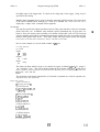
DESCRIPTION
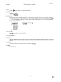
The analyzer monitor displays graphically the state of the inputs (inA, iti, . ..) connected to it. The
traces are displayed in real time (while the simulation is running). The state of the inputs is maintained
internally so that the traces can be viewed once the simulator has finished.
The view is split into 2 sub-windows: a trace window, and a text window. The text window is used to
enter commands and display command results.
The trace window displays the following information:
signal names for traces.
left:
top:
right:
From left to right; first time recorded, time of first trace displayed, time of last trace displayed,
last time recorded. In the center, the time of the current cursor position.
Values of the signals under the cursor.
Command Syntax
Commands are invoked by typing the command name followed by its arguments, if any. A Command
name can be abbreviated, just so long as enough characters are typed to distingish it from all other
commands. Command names and options are case insensitive.
Signal names can be specified by using regular expressions similar to the ones provided by csh. The
following metacharacters are provided:
*
Matches any sequence of 0 or more characters.
?
Matches any single character.
[abc]
Matches any of the characters (a b c) enclosed by 0.
[cl-c2] Matches any characters in the range [cl..c2]
[n&n21 Matches any number in the range [nl ..n2].
\
Escapes any of the previous metacharacters.
Although each regular expression is matched in the order in which it is entered, NO sorting of the
matching names is performed, so there’s no guarantee as to what the order of the resulting name list
will be, furthermore, the same name may be matched twice as for example:
a? a* will expand to al a2 al a2 al0, with inputs al, a2, and a10.
Commands
The following commands are available for the analyzer:
add sigl . . . sigN [b=num]
Add a new trace consisting of signals sigh . . . sighr and display the value of the signal group
using base num. Bases 2 (binary), 8 (octal), and 16 (hex) are available. If no base is specified,
base 16 will be used, There is no restriction on what signals may be grouped in a single trace,
but the maximum number is limited to 32 bits. Sigl will be the LSB, and sigN the MSB.
Remember that sigl . ..sigN are regular expressions. The name of a trace consisting of more
than 1 signal, will be displayed as follows:
name[nl-n2] for a group of signals with common prefix name and the numerical postfix nl
and n2 of the 1st and last signals, respectivelly.
1
( 1>
analyzer ( 3 )
THOR USER’S MANUAL
GRP n [xl
analyzer ( 3 )
for a group of signals with no common prefix; where n is the number of such a
trace, and x is the number of signals in the trace.
autostop [onloff)
Turns auto-stop on or off. With no arguments, the command prints the auto-stop status. If
autostop is turned on the analyzer will stop the simulator if a trigger point is found (see trace
below).
base trace-rum num
Change the display base of trace trace-nun to base num (2, 8, or 16 ). Traces are numbered
l..n, starting with the topmost trace.
Clear the text window and move the cursor to the topmost line.
blank
continue
Alow the simulator to continue. The simulator may be stopped by either: (1) a stop command,
(2) a trigger point was found and autostop was on, and (3) a lack of memory. Note that the
state of the simulator is shown in the window banner.
delete tnum
The trigger point corresponding to tnum is removed. The numbers associated with trigger
points are printed by the status command.
display numl num2
Move trace number num2 to the position occupied by trace num2. The traces are shifted up or
down as required.
exec jilename
Execute analyzer commands from file filename.
Find the first trigger point and move the cursor to that time.
Find the last trigger point and move the cursor to that time.
last
list sigl . . . sigN
List the signals that match the regular expressions sigl . . . sigN.
lines number
Enlarge or shrink the text window to contain number lines. The current limit is [2-lo].
first
help [commands]
With no arguments it prints the list of commands, otherwise a short description of each
command is printed. Again, commands may be abbreviated.
move
move
move
move
move
left
right
beginning
end
time-step
Move the cursor to the specified position, or time-step and center the traces around that point.
Left and right cause the screen to scroll by one 1 “page”.
previous
Find the next (previous) trigger point (starting at the current cursor position) and move the
cursor to that point. Center the traces around the time-step if such a trigger is found.
print [name] [timel-tirne2]
Generate a PostScript file of the traces from time-step time1 through time2. With no
arguments it prints a copy of the screen to file model-name.ps. Lf name is specified then the
output is written to that file. The number of time-steps per page is the same as shown on the
2
(2)
THOR USER’S MANUAL
analyzer ( 3 )
quit
analyzer ( 3 )
screen.
Exit from the analyzer. Note that the simulator will continue running if it hasn’t finished yet.
remove tnum
Remove trace number tnum from the display.
redraw Redraw the whole window.
reclaim [time]
Reclaim memory up to (not including) time-step time. This command is useful, should the
analyzer run out of memory to store previous traces. If this should happen, a warning will be
printed and the simulator will be stopped. This will give the user a chance to write/print the
traces before continuing. If time is not specified, the analyzer will reclaim half the memory
used.
read name
Read file name, previously written by the analyzer, and allow interactive viewing of the stored
traces.
status [trig-num]
Print information about the specified trigger point. If no argument is given a concise list of all
triggers is printed.
stop
Stop the simulator at the next time-step (provided it’s still running).
trace signals = value
Add a trigger point on signals being equal to value. value can be any of U (undefined), Z
(float), X (change), or a number. Numbers can be specified in base 2 (preceding the number
by ‘Ob’), 8 (preceding the number by ‘O’), 10 (the default), and 16 (preceding the number by
‘Ox’). For example:
trace a b c d = ObllOl => trace that a=1 and b=O and c=l and d=l.
trace address[l-31 = U => trace that addressl=U and address2=U and address3 = U.
Notice that the LSB is always the leftmost signal.
trace signals 1 value
Add a trigger point on ANY of signals having value. For example:
trace [a-d] 1 ObOlOl => trace that a=1 or b=O or c=l or d=O.
trace x y z 1 2 => trace that either x, y, or z become float.
width num
Set the trace display to num time-steps (minimum 1).
whatis tnum
Print information about trace number tnum; the signals that it’s composed of and its display
base.
write [name] [t=time]
Write file name containing the current state (traces, triggers, etc) so that it may be viewed
later. If time is specified then the traces are written only up to that time. If the filename is not
specified the file model-name.ana will be written.
zoom in
zoom out
Zoom in or out by fat tor of 2.
zoom seeAl
Zoom out to show all the traces.
(3)
THOR USER’S MANUAL
analyzer ( 3 )
analyzer ( 3 )
Mouse Functions
The analyzer only uses the left mouse button. The other buttons will retain their usual meaning in
Interviews. Various functions are provided depending on where in the window the button is depressed,
as follows:
In Signal names:
The trace under the mouse is selected and will be moved to the trace position where the button
is released, If the button is released outside the traces area the selected trace will be removed
from the display.
In Left/Right arrow:
The traces are scrolled left/right by half a “page”. The cursor is not moved.
In the scrollbar:
If the mouse is depressed over the white box it can be stretched left/right, up to the point
where the button is released. This is equivalent to zooming in/out by an arbitrary factor. The
cursor is not moved
If the mouse is depressed in the gray area under the white box the visible part of the traces
can be moved left/right up to the point where the mouse is released. The cursor is not moved.
If the mouse is depressed in the gray area outside the white box the window will be centered
around the corresponding time-step. The cursor will be moved to the selected position.
In the traces:
The cursor is moved to the time-step closest to the mouse position.
SEE ALSO
gensim( 1)
banalyzer ( 3 )
THOR USER’S MANUAL
banalyzer ( 3 )
NAME
banalyzer - batch analyzer monitor for THOR
SYNOPSIS
(m=banalyzer)(n=model-name)(i=inA, i&3, . ..)(s=3)(vs=O)
DESCRIPTION
The banalyzer monitor writes the state of its inputs to the file model-nanze.batch so that they can be
latter viewed by either the graphic analyzer (see ana(1) ) or in ascii (see aview(1) ).
The file generated by the analyzer has the following format:
<time> : &AxinB>....
Each such line contains an ascii representation of the signal associated with it. The header of the file
contains the number of inputs and the names of the signals connected to the analyzer.
SEE ALSO
gensim( 1) ana( 1) aview( 1)
current-time ( 3 )
THOR USER’S MANUAL,
current-time (3)
NAME
current-time - current absoluk time
SYNOPSIS
#include “mode1.h”
extern int current-time;
current time is a copy of the simulator’s absolute time variable. It’s units are in simulator time steps.
The sir&lator starts at time 0, and proceeds from there. All generator and monitor models are called at
time 0.
Note that mode2.h is included automatically by mkmd(l).
FILES
model. h
SEE ALSO
self-sched(3), mname(3), mkmod( l), THOR{ 1)
AUTHORS
Beverly Vellandi
Henry Vellandi
University of Colorado, Boulder
May 1985
.
THOR USER’S MANUAL
fadd( 3)
fadd(3)
NAME
fadd - Unsigned bitwise addition of two signal groups
SYNOPSIS
fadd(grpout,msbo,Isbo,grpinl,msbl,lsbl,grpin2,msb2,Isb2,carryin)
int msbo,lsbo,msbl,msb2,lsb2,carryin;
GRP grpout,grpinl,grpin2;
DESCRIPTION
Unsigned bitwise addition of the specified bits of grpinl to grpin2 with carryin as input carry and then
places the output in the specified bits of grpout. The carry out is returned by the function if no error
occurs. If an error occurs the error code will be returned (see ferr).
FILES
SEE ALSO
fsub(3), fsubc(3), faddc(3), vadd(3)
BUGS
(1>
.
fadcic(3)
THOR USER’S MANUAL
faddc ( 3 )
NAME
faddc - Unsigned bitwise addition of a group to a number
SYNOPSIS
faddc(grout,msbo,lsbo,grinl,msbl,lsbl,number,carrin)
int carryout,lsbo,msbl,lsbl,number,carryin;
GRP grout,grinl;
DESCRIPTION
Unsigned bitwise addition of the specified bits of grid to number with carryin as input carry and then
places the output in the specified bits of grout. The carry out is returned by the function if no error
occurs. An error code is returned on detection of an error condition (see ferr).
FILES
SEE ALSO
fadd(3), fsubc(3), fsub(3)
BUGS
(1)
.
fand(3)
THOR USER’S MANUAL
fand(3)
NAME
fand - Logically ands specified bits of two signal groups
SYNOPSIS
fand(grout,msbo,lsbo,grinl,msbl,lsbl,grin2,msb2,lsb2)
int msbo,lsbo,msbl,lsbl,msb2,lsb2;
GRP grout,grinl,grin2;
DESCRIPTION
Logically ands specified bits of grid and grin2 and then places the output in the specified bits of
grout. See vand for a description of the logical and truth table.
FILES
SEE ALSO
vand(3), fandc(3)
BUGS
(1>
fandc(3)
THOR USER’S MANUAL
fandc ( 3 )
NAME
fandc - Logically and a signal group with a number
SYNOPSIS
fandc(grout,msbo,lsbo,grinl,msbl,lsbl,number)
int msb0,lsbo,msbl,lsbl,number;
GRP grout,grinl;
DESCRIPTION
Logically ands specifxd bits of grid and rumbet and then places the output int the specified bits of
grout. See vor for the truth table for the logical or function.
FILES
SEE ALSO
vand(3), fand(3)
BUGS
-IO
fcat( 3)
THOR USER’S MANUAL
feat ( 3 )
NAME
feat - concatenates specified bits of two signal groups
SYNOPSIS
fcat(grout,msbo,lsbo,grinl,msbl,lsbl,grin2,msb2,lsb2)
int msbo,lsbo,msbl,lsbl,msb2,lsb2;
GRP grout,grinl,grin2;
DESCRIPTION
Concatenates specified bits of grid to grin2 and places the output in the specifed bits of grout. Grin1
will be the most significant portion of grout.
FILES
SEE ALSO
fcatac(3), fcatca(3), fcopy(3)
BUGS
11
(1)
fcatac ( 3 )
THOR USER’S MANUAL
fcatac ( 3 )
NAME
fcatac - concatenates specified’ bits of a signal group with a number
SYNOPSIS
fcatac(grout,msbo,lsbo,grinl,msbl,lsbl,number)
int msbo,lsbo,msbl,lsbl,number;
GRP grout,grinl;
DESCRIPTION
Concatenates specified bits of grid to number and places the output in the specifed bits of grout. Grid
will be be the most significant portion of grout.
FILES
SEE ALSO
fcatca(3), feat(3), fcopy(3)
BUGS
12
(1)
fcatca ( 3 )
THOR USER’S MANUAL
fcatca ( 3 )
NAME
name - Concatenates specifed bits of a number with a signal group
SYNOPSIS
fcatca(grpout,msbo,lsbo,number,grpinl,msbl,lsbl)
int msbo, lsbo, number, msbl, lsbl;
GRP grpout, grpinl;
DESCRIPTION
Concatenates specified bits of number to grpinl and places the output in the specifed bits of grpout.
Number will be be the most significant portion of grpout.
FILES
SEE ALSO
catac(function), fcat(function), fcopy(function)
BUGS
13
(1)
fckbin ( 3 )
THOR USER’S MANUAL
fckbin (3 )
NAME
fckbin - checks that all bit values in the signal group are in the set {ZERO, ONE}
SYNOPSIS
fckbin(grpin,msb,lsb)
int msb, lsb;
GRP grpin;
DESCRIPTION
Tests to see that all values of the bits between Zsb and msb of the signal group grpin are in the set
{ZERO, ONE}.
RETURNS
Returns PASSED if all values are valid otherwise it returns the value BINERROR.
FILES
SEE ALSO
fckvalue(3), fckrange(3), f&m&e(3), fckpty(3)
BUGS
14
(1)
fckmsize ( 3 )
THOR USER’S MANUAL
fckmsize ( 3 )
NAME
fckmsize - Verifies that the lsb md msb of a signal group is not larger than allowed
SYNOPSIS
fckmsize(msb,lsb)
int msb,lsb;
DESCRIPTION
Checks to see that the range from Zsb to msb is not larger than the maximum allowed word size. The
maximum allowed word size is defined as MAXBUSLEN-.
RETURNS
Returns PASSED if the range is valid otherwise MSIZEERROR is returned.
F’ILES
SEE ALSO
fckrange( 3)
BUGS
15
fckpty ( 3 1
THOR USER’S MANUAL
fckpty(3)
NAME
fckpty - computes the type of parity of the specifed bits of a signal group
SYNOPSIS
fckpty(grpin,msb,lsb)
int msb,lsb;
GRP grpin;
DESCRIPTION
An ODD/EVEN parity check is performed on the specifed bits of grpin. The parity is EVEN is the
number of ONES in the group is EVEN and is ODD otherwise.
RETURNS
Returns ODD if odd parity is detected. Returns EVEN if even parity is detected. Returns a value <=
FAILED if an error is encountered.
FILES
SEE ALSO
fckvalue( 3), fckbin( 3)
BUGS
16
(1)
fckrange ( 3 )
THOR USER’S MANUAL
f&range ( 3 )
NAME
f&range - verifies range of an (msb,lsb) Pair
SYNOPSIS
fckrange(msbl,lsbl,msb2,lsb2)
int msbl,lsbl,msb2,lsb2;
DESCRIPTION
Verifies that the ranges (i.e. Imsb-lsbl) of the msb,lsb pairs are equal. The distance between the msb
and Zsb must be the same for each pair. The value of the msb and lsb in each pair do not need to be
equal.
RETURNS
Returns PASSED if the ranges are equal, otherwise RANGEERROR is returned.
FILES
None.
SEE ALSO
fckrange3(3), fckmsize(3)
BUGS
17
f&range3 ( 3 )
THOR USER’S MANUAL
f&range3 ( 3 )
NAME
f&range3 - verifies range of an (msb,lsb) for three functions
SYNOPSIS
fckrange3(msbl,lsbl,msb2,lsb2,msb3,lsb3)
int msbl,lsbl,msb2,lsb2,msb3,lsb3;
DESCRIPTION
Verifies that the ranges (i.e. jrnsb-lsbl) of the msb,lsb pairs are equal. The distance between the m.sb
and Zsb must be the same for each pair. The value of the tnsb and Isb in each pair do not need to be
equal.
RETURNS
Returns PASSED if the ranges are equal, otherwise RANGEERROR is returned.
FILES
None.
SEE ALSO
fckrange(3), fckmsize(3)
BUGS
18
fckvalue ( 3 )
THOR USER’S MANUAL
fckvalue ( 3 )
NAME
fckvalue - checks for invalid values in a signal group
SYNOPSIS
fckvalue(grpin,msb,lsb)
int msb,lsb;
GRP grpin;
DESCRIPTION
Fckvalue checks if the signal group grpin contains allowable values. It tests to see if the values in
the bits specified by msb and Zsb are in the allowable set {ONE, ZERO, UNDEF, FLOAT}.
RETURNS
Returns PASSED if all values are legal, otherwise VALUEERROR is returned.
FILES
SEE ALSO
fckbin(3)
BUGS
19
(1)
fCOPY ( 3 )
THOR USER’S MANUAL
fCOPY ( 3 )
NAME
copy - Copies the specified bits of one signal group to another group
SYNOPSIS
fcopy(grpout,msbo,lsbo,grpin,msbi,lsbi)
int msbi, lsbi, msbo,lsbo;
GRP grpout, grpin;
DESCRIPTION
Copy the specified bits of grpin into the specified bits of grpout.
FILES
SEE ALSO
feat(3), fcatac(3), fcatca(3)
BUGS
20
(1)
fcopyinv ( 3 )
THOR USER’S MANUAL
fcopyinv ( 3 )
NAME
copy - Copies and inverts the specified bits of one signal group to another group
SYNOPSIS
fcopyinv(grpout,msbo,lsbo,grpin,msbi,lsbi)
int msbi, lsbi, msbo,lsbo;
GRP grpout, grpin;
DESCRIPTION
Copy the specified bits of grpin into the specified bits of grpout. It inverts each bit as it is copied.
FILES
SEE ALSO
feat(3), fcatac(3), fcatca(3), vinv(3)
BUGS
21
( 1>
fdecr( 3)
THOR USER’S MANUAL
fdecr ( 3 )
NAME
fdecr - decrements the value of specified portion of a signal group
SYNOPSIS
fdecr(grpin, msb, lsb)
int msb, lsb;
GRP grpin;
DESCRIPTION
The specifed portion of the signal group grpin is decremented by 1. No borrow is returned.
Decrementing zero returns all ones in the specified pportion of the group.
RETURNS
Returns the integer value of the specified range. Note that the input group, grpin also contains the
decremented value. Returns a value c= FAILED if an error occurs.
FILES
SEE ALSO
finer(3), fpack(3), funpack(3), fadd(3), fsub(3)
BUGS
22
m=(3)
THOR USER’S MANUAL
FDUMP(3)
FDUMP
name - FDUMPON, FDUMPOFF
SYNOPSIS
FDUMPON
FDUMPOFF
DESCFUPTION
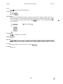
These macros are used to turn the FDUMP- flag on and off when debugging is desired in a f function.
FDUMPON turns on the function dumping flag FDUiW- which causes the fxxr functions to dump the
contents of the input and output groups when the routine exits. The macro FDUMPOFF is used to
turn the dumping off.
You can use these macros when you are debugging models that use the f functions. This allows you to
see the contents of the input and output parameters to the f functions during execution. Keep in mind
that the data that is presented is the contents of the input and output groups when the f routine EXITS.
The names of the inputs and outputs are the same as the names given in the HELP function
descriptions.
The macros are defined in the file $THOIUinclude/uarp.h.
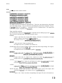
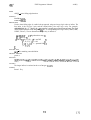
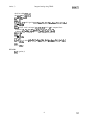
The following is an example of the output from the fcopy function:
FCOPY: input group grpin:
msb
7 6 5 4 3
1 0 2 1 0
FCOPY: output group grpout:
msb
4 3 2 1 0
1 0 2 1 0
RETURNS
All output is directed to standard out (s&lout).
FILES
None.
SEE ALSO
fprval( 3)
BUGS
Not all f functions use the FDUMP flag yet.
23
( 1>
THOR USER’S MANUAL
ferr( 3)
ferr(3)
NAME
ferr - prints the type of errof requested
SYNOPSIS
ferr(error,comment)
int error;
char comment[];
DESCRIPTION
Fur prints the descriptions of the errors in the input parameter error. The parameter comment will be
prepended to the default message printed by ferr. Normally the name of the calling routine is put in
comment. Since errors may be ORed together, error may contain more than one error. Ferr will print
all of the errors it finds. The following errors are recognized (found in esimerr0r.h):
P A S S - No error found.
PASSED
- No error found.
VALUEERROR
- bit value not in the set {0,1,2,3}
RANGEERROR
- msb-lsb do not match for groups compared
MSIZEERROR
- size of groups is too large: abs(msb-lsb) > MAXBUSLENBINERROR
- bit value not in the set (0, l}
FAIL - general failure
UNDEFERROR
- UNDEF value found when not expected
FLOATERROR
- FLOAT value found when not expected
INERROR
- wrong number of inputs detected
OUTERROR
- wrong number of outputs detected
STERROR
- wrong number of states detected
BIERROR
- wrong number of buputs detected
MODERROR
- general failure in a model
RETURNS
The value PASSED is returned.
EXAMPLE
The following is an example of how to use this call:
if ((x = fckbin(group,msb,lsb)) == BINERROR)
1
ferr(x,“TEST ROUTINE: ‘I);
24
(1)
.
THOR USER’S MANUAL
ferr( 3)
ferr(3)
The ferr routine will print oqt in readable format the result of the fckbin call that is stored in the
variable x. The parameter “TEST ROUTINE: ” will be prepended to the default message that is printed
by ferr.
FILES
esimerr0r.h - error codes
SEE ALSO
perfor@)
25
fgetval ( 3 )
THOR USER’S MANUAL
fgetval ( 3 )
NAME
fgetval - Interactive routine to initialize a signal group
SYNOPSIS
fgetval(grpin, msb, lsb)
int msb, Isb;
GRP grpin;
DESCRIPTION
Prompts the user to input the values of each bit of the specified portion of the group gpin. The input
always starts with the Zsb value and ends after the user enters the msb value.
RETURNS
Returns the filled in group if no errors occur. A value c= FAILED is returned if an error occurs.
FILES
SEE ALSO
fprval(3), fsetword(3)
BUGS
26
THOR USER’S MANUAL
fincr( 3)
finer(3)
NAME
finer - increments the value of specified portion of a signal group
SYNOPSIS
fincr(grpin, msb, lsb)
int msb, lsb;
GRP grpin;
DESCRIPTION
The specifed portion of the signal group grpin is incremented by 1. No carry or overflow is returned.
Incrementing all ones returns all zeroes in the specified portion of the group.
RETURNS
The group grpin contains the incremented value. Returns a value <= FAKED if an error occurs.
FILES
SEE ALSO
fdecr(3), fpack(3), funpack(3), fadd(3), fsub(3)
BUGS
27
(1)
THOR USER’S MANUAL
finitmem ( 3 )
finitmem ( 3 )
NAME
finitmem - Initializes memory
SYNOPSIS
fMtmem(file,mem,nwords,wsize)
char *file;
int nwords, wsize;
GRP mem;
DESCRIPTION
Initializes random access memory from a file containing the initialization data. Memory is declared
using the GRP type declaration in the ST LIST portion of the model being defined. The group mem is
declared to be nwords x wsize long. where nwords is the number of words of memory defined and
wsize is the size of each word
The format of the data file is:
address data
comment
where:
address - the hex address to put the data.
data
- the data to be stored (in hex).
- any text until the end of line is a comment.
comment
For example:
ST-LIST
GRP(mem256);
ENDLIST
.
finit(“datafile”,mem,32,8);
This will declare and initialize the memory mem from the file afatajile. Mem has 32 words with each
word being 8 bits long.
RETURNS
Returns the value MODERROR if an error occurs during the initialization other wise it returns
PASSED.
FILES
SEE ALSO
BUGS
28
(1)
THOR USER’S MANUAL
finv(3)
finv(3)
NAME
finv - invert specified bits of a signal group
SYNOPSIS
finv(grpout,msbo,lsbo,grpiul,msbl,lsbl)
int lsbo,msbo,msbl,lsbl;
GRP grpout, grpinl;
DESCRIPTION
Logically inverts specifkd bits of grpinl and then places the output in the specified bits of grpout.
F’ILES
SEE ALSO
vinv( 3)
BUGS
29
(1 >
THOR USER’S MANUAL,
fior(3)
fior(3)
NAME
fior - Logically ORs specified bits of two signal groups
SYNOPSIS
fior(grpout,msbo,lsbo,grpin1,msbl,lsbl,grpin2,msb2,lsb2)
int msbo, lsbo, msbl, lsbl, msb2,lsb2;
GRP grpout, grpinl, grpin2;
DESCRIPTION
Performs a logical inclusive OR of the spectied bits of grpinl and grpin2 and then places the output in
the specified bits of grpout. Msbo, Zsbo, msbl, Zsbl, msb2, lsb2 specify the most signifkant and least
significant bit positions for each group.
FILES
SEE ALSO
vor(3), fiorc(3)
BUGS
30
(1 >
THOR USER’S MANUAL
fiorc(3)
fiorc(3)
NAME
fiorc - Logically ORs the specifed bits of a signal group with number
SYNOPSIS
fiorc(grpout,msbo,lsbo,grpinl,msbl,lsbl,number)
int msbO,Isbo,msbl,lsbl, number;
GRP grpout, grpinl;
DESCRIPTION
Performs an inclusive OR of the specified bits of grpinl and number and then places the output in the
specified bits of grpout. The bits used in number have the same msb-lsb correspondence as grpinl.
FILES
SEE ALSO
fior( 3), vor( 3)
BUGS
31
(1 >
fp=W)
THOR USER’S MANUAL
fpaW3)
NAME
fpack - convert specified bits of a signal group to a number
SYNOPSIS
fpack(grpin,msb,lsb)
int msb,lsb;
GRP grpin;
DESCRIPTION
Packs(converts) specified bits of the signal group grpin into an integer number. Packing is done on
unsigned groups of bits only (i.e. no sign is assumed for the most significant bit). The integer is
returned by the function if no errors occured. If an error occured then an error code is returned (i.e. a
value less than zero).
RETURNS
Returns the integer derived from the input signal group if no conversion errors are encountered
otherwise a value less than zero is returned indicating an error has occured.
FILES
SEE ALSO
funpack( 3)
BUGS
The routine will attempt to pack integers larger than the machine will allow. The user must be aware of
the maximum size of integers allowed on the machine running the program.
32
(1)
.
fprvd(3)
THOR USER’S MANUAL
fprvaV3)
NAME
fprval - prints the contents of the specified portion of a signal group
SYNOPSIS
fprval(grpin, msb, lsb)
int msb, lsb;
GRP grpin;
DESCRIPTION
Prints on stdout the values of the specifed positions of the signal group grpin. Any value present is
printed. No validity checking is made on the values before they are printed. The ordinal position and
the relative positions of each value are printed along with the value of each position. The printout
always starts with the Zsb position.
RETURNS
A value <= FAILED is returned if an error occurs.
FILES
SEE ALSO
fgetval(3), fsetword(3)
BUGS
33
fprvec ( 3 )
THOR USER’S MANUAL
f@-=(3)
NAME
fprvec - Prints the contents of the specified portion of a signal group
SYNOPSIS
fprvec(grpin, msb, lsb, comment)
int msb, lsb;
char *comment;
GRP grpin;
DESCRIPTION
Prints on stdout the values of the specifed positions of the signal group grpin. The comment string is
printed followed by the msb and Zsb values specifed by the user. The value of the group are printed as
1, 0, U, F for each of the allowable signal values. Any other value is printed without conversion.
RETURNS
A value <= FAILED is returned if an error occurs.
FILES
SEE ALSO
fgetval(3), fprval(3), fsetword(3)
BUGS
34
(1)
frorl ( 3 )
THOR USER’S MANUAL
frorl ( 3 )
NAME
fiorl - circularly rotates from lsb to msb the specified number of bits
SYNOPSIS
frorl(grpin,msb,lsb,number)
int number,msb,lsb;
GRP grpin;
DESCRIPTION
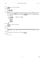
Rotates all bits of grpin from lsb to msb the number of positions specified by number. The direction of
rotation is from Zsb to msb. The rnsb position is circularly rotated into the lsb position. Example:
if reg contains (lsb-xnsb):
01234
and frorl(reg,2) is performed then reg will then contain:
34012
(lsb->msb):
The carry out is equal to 3.
RETURNS
The last bit rotated out of the msb position is returned by the function if no errors occur. A value less
than zero is returned on error (see ferr(3)).
FILES
SEE ALSO
frorr(3), fshftl(3), fshftr(3), ferr(3)
BUGS
35
(1)
THOR USER’S MANUAL
frorr( 3)
frorr(3)
NAME
frorl - circularly rotates from msb to lsb the specified number of bits
SYNOPSIS
fkorr(grpin,msb,lsb,number)
int number,msb,lsb;
GRP grpin;
DESCRIPTION
Rotates all bits of grpin from nub to Zsb the number of positions specified by number. The direction of
rotation is from msb to lsb. The Zsb position is circularly rotated into the msb position.
RETURNS
The last bit rotated out of the lsb position is returned by the function if no emors occur. A value less
than zero is returned on error (see ferr(3)).
FILES
SEE ALSO
frorl(3), fshftl(3), fshftr(3), ferr(3)
BUGS
36
fsckbin ( 3 )
THOR USER’S MANUAL
fsckbin (3 )
NAME
fsckbin - checks that the value of the signal are in the set {ZERO, ONE}
SYNOPSIS
fsckbin(sig)
sig;
SIG
DESCRIPTION
Tests to see that the value of the signal sig are in the set {ZERO, ONE}.
RETURNS
Returns PASSED if the value is valid otherwise it returns the value BINERROR.
FILES
SEE ALSO
fckvalue(3), fckrange(3), fckmsize(3), fckpty(3), fckbin(3)
BUGS
37
(1 >
fsetword ( 3 )
THOR USER’S MANUAL
fsetword ( 3 )
NAME
fsetword - set all specified bits in a signal group to a value
SYNOPSIS
fsetword(grpin, msb, lsb, value)
int msb, lsb, value;
GRP grpin;
DESCRIPTION
Sets all of the bits specifed by the msb - Zsb range to the value specified by value. Value may be my
value.
RETURNS
Returns PASSED if no erros are detected. Otherwise it returns a value <= FAILED.
F’ILES
SEE ALSO
fgetval(3)
BUGS
38
(1)
fshftl ( 3 )
THOR USER’S MANUAL,
fshftl ( 3 )
NAME
fshftl - shifts the specified bitS of grpin to the left by number bits
SYNOPSIS
fshftl(grpin,msb,lsb,number$hiftin)
int shiftin, msb, lsb;
GRP grpin;
DESCRIPTION
Shifts the specifkd bits of grpin to the left (lsb to msb) the number of bits specified by number. The
value of sh#in is shifted in to replace the least significant bits shifted to the left.
RETURNS
The last bit shifted out of the mb position is returned by the function. If an error occurs then the value
returned is less than zero (see ferr(3)).
FILES
SEE ALSO
fshftr(3), frorl(3), frorr(3), ferr(3)
BUGS
39
fshftr ( 3 )
THOR USER’S MANUAL
fshftr ( 3 )
NAME
fshftr - shifts the specified bits of grpin to the right by number bits
SYNOPSIS
fshftr(grpin,msb,lsb,number,shiftin)
int shiftin, msb, lsb;
GRP grpin;
DESCRIPTION
Shifts the specified bits of grpin to the right (msb to lsb) the number of bits specified by number. The
value of shzjlin is shifted in to replace the most significant bits shifted to the right.
RETURNS
The last bit shifted out of the Zsb position is returned by the function. If an error occurs then the value
returned is less than zero (see ferr(3)).
FILES
SEE ALSO
fshftl(3), frorl(3), frorr(3), ferr(3)
BUGS
40
fshftr0 ( 3 )
THOR USER’S MANUAL
fshftro(3)
NAME
fshftr0 - shifts the specified bits of grpin to the right by number bits
SYNOPSIS
fshftrO(grpout,msbo,lsbo,grpin,msb,lsb,number)
int msbo, lsbo, msb, Isb;
GRP grpout, grpin;
DESCRIPTION
Shifts the specified bits of grpin to the right (msb to lsb) the number of bits specified by number. ZERO
is shifted in to replace the most significant bits shifted to the right.
RETURNS
If an error occurs then the value returned is less than zero (see ferr(3)).
FILES
SEE ALSO
fshftl(3), fshftr(3), frorl(3), fiorr(3), ferr(3)
BUGS
41
( 1>
THOR USER’S MANUAL,
fsub( 3)
fsub(3)
NAME
fsub - Unsigned bitwise subtkion of two signal groups
SYNOPSIS
fsub(grpout,msbo,lsbo,grpinl,msbl,lsbl,grpin2,msb2,lsb2,borrowin)
int msbo,lsbo,msbl,msb2,Isb2,borrowin;
GRP grpout,grpinl,grpin2;
DESCRIPTION
Unsigned bitwise subtraction of the specified bits of grpin2 from grpinl with borrowin as the borrow
bit and then places the output in the specified bits of grpout. The borrowin bit is subtracted from the
Zsb position before the two groups are subtracted. The borrow out bit is ONE if a borrow is needed in
the msb position during the subtraction.
RETURNS
The borrow out is returned by the function if no error occurs. If an error occurs an error code <=
FAILED will be returned (see fen-).
FILES
SEE ALSO
fadd(3), fsubc(3)
BUGS
42
(1>
.
fsubc ( 3 )
THOR USER’S MANUAL
fsubc (3 )
NAME
fsubc - Unsigned bitwise subtraction of a number from a signal group
SYNOPSIS
fsubc(grpout,msbo,lsbo,grpinl,msbl,lsbl,number,borro~n)
int msbo,lsbo,msbl,number,borrowin;
GRP grpout,grpinl;
DESCRIPTION
Unsigned bitwise subtraction of an integer, number from grpinl with borrowin as the borrow bit and
then places the output in the specified bits of grpout. The borrowin bit is subtracted from the Zsb
position before the integer number is subtracted. The borrow out bit is ONE if a borrow is needed in
the msb position during the subtraction.
RETURNS
The borrow out is returned by the function if no error occurs. If an error occurs an error code <=
FAILED will be returned (see fen-).
FILES
SEE ALSO
fadd(3), fsub(3)
BUGS
43
fswap ( 3 )
THOR USER’S MANUAL
fswap ( 3 )
NAME
fswap - Exchange bits in two signal groups
SYNOPSIS
fswap(grpout,msbo, Isbo, grpin, msbi, lsbi)
int msbo, lsbo, msbi, lsbi;
GRP grpout, grpin;
DESCRIPTION
Takes the bits specified by msbi and Zsbi and exchanges them with the corresponding bits specifed by
msbo and Zsbo. The bits are swapped by placing the lsb of grpin into the msb of grpout. The msb and
lsb of the input and output must have the same range.
RETURNS
PASSED is returned if no erros occur. Otherwise an error code <= FAILED is returned.
FILES
SEE ALSO
fcopy(3), feat(3), fcatac(3), fcatca(3)
BUGS
44
( 1>
funpack ( 3 )
THOR USER’S MANUAL
funpack ( 3 )
NAME
funpack - Convert a number into binary signal group
SYNOPSIS
funpack(grpout, msb, lsb, number)
int msb, lsb, number;
GRP grpout;
DESCRIPTION
Converts the value of number and stores the result in the signal group grpout. No sign is assumed in
number. The conversion is done by shifting each bit of number into grpout starting with the lsb
position.
RETURNS
Returns PASSED if no error occurs. Other wise an error code c= FAILED is returned.
FILES
SEE ALSO
fp=kO)
BUGS
Does not check for overflow when converting number.
45
fxnor ( 3 )
THOR USER’S MANUAL
fxnor ( 3 )
NAME
fxnor - Performs a logical exclusive nor on the specified bits of the signal groups
SYNOPSIS
fxnor(grpout,msbo,lsbo,grpinl,msb1Jsbl,grpin2,msb2,lsb2)
int msbo,lsbo,msbl,lsbl,msb2,lsb2;
GRP grpout,grpinl,grpin2;
DESCRIPTION
Performs a logical exculsive nor on the specified bits of grpinl and grpin2 and then places the output in
the specified bits of grpout. The effect is to return a one in for those values of grpinl and grpin2 that
are equal.
RETURNS
Returns PASSED if no errors occured. It returns a value <= FAILED if an error occurs.
FILES
SEE ALSO
fxnorc(3), fxor(3), fxorc(3), fior(3), fiorc(3), vxnor(3)
BUGS
46
.
fxnorc ( 3 )
THOR USER’S MANUAL
fxnorc ( 3 )
NAME
fxnorc - Performs a logical exclusive nor of then specified bits of a signal group and an integer
SYNOPSIS
fxnorc(grpout,msbo,lsbo,grpinl,msbl,kbl,number)
int msbo,kbo,msbl,lsbl,number;
BUS grpout,grpinl;
DESCRIPTION
Performs an exclusive nor on the specified bits of grpinl and number and then places the output in the
specified bits of grpout. See vxnor(3v) for the exclusive nor truth table. The bits of number selected
are the same as the bits selected for grpinl.
RETURNS
Returns PASSED if no errors occur. Returns a value <= FAILED if an error occurs (see ferr(3)).
FILES
SEE ALSO
fxnor(3), fnorc(3), fiorc(3), vxnor(3v)
BUGS
47
(1)
THOR USER’S MANUAL,
fxor( 3)
fxor(3)
NAME
fxor - Performs a logical exclusive or on the specified bits of the signal groups
SYNOPSIS
fxor(grpout,msbo,lsbo,grp~l,msbl,~bl,grp~2,msb2~sb2)
int msbo,lsbo,msbl,lsbl,msb2,lsb2;
GRP grpout,grpinl,grpin2;
DESCRIF’TION
Performs a logical exclusive or on the specified bits of grpinl and grpin2 and then places the output in
the specified bits of grpout.
RETURNS
Returns PASSED if no errors occured. It returns a value <= FAILED if an error occurs.
FILES
SEE ALSO
fxorc( 3), fxnor( 3), fxnorc( 3), fior( 3), fiorc( 3), vxor(3)
BUGS
48
(1)
THOR USER’S MANUAL
fxorc(3)
fxorc ( 3 )
NAME
fxorc - Performs a logical exclusive or of the specified bits of a signal group and an integer
SYNOPSIS
fxorc(grpout,msbo,lsbo,grpinl,msbl,lsbl,number)
int msbo,lsbo,msbl,lsbl,number;
BUS grpout,grpinl;
DESCRIPTION
Performs an exclusive or on the specified bits of grpinl and number and then places the output in the
specified bits of grpout. See vor(3) for the exclusive or truth table. The bits of number selected are the
same as the bits selected for grpinl.
RETURNS
Returns PASSED if no errors occur. Returns a value <= FAILED if an error occurs (see ferr(3)).
FILES
SEE ALSO
fxor(3), fxnor(3), fnorc(3), fiorc(3), vxor(3)
BUGS
49
(1)
THOR USER’S MANUAL
P-0)
FW)
NAME
gen - signal generator models available
SYNOPSIS
(g=ZERO)(n=username)(o=n-outputs);
(g=ONE)(n=username)(o=n_outputs);
(g=UNDEF)(n=username)(o=n_outputs);
(g=FLOAT)(n=username)(o=n_outputs);
(g=CLOCK)(n=username)(o=l_output)(s=3)(vs=begin,trans,period);
(g=COUNT)(n=username)(o=n_outputs)(s=l)(vs=period);
(g=DCOUNT)(n=username)(o=n_outputs)(s=l)(vs=period);
(g=FSIG)(n=username)(o=n_outputs)(s=2);
(g=PATRN)(n=username)(o=n_outputs)(s=2_or-more)(vs=period,pattern..);
(g=ROT8L)( n=username)(o=n_outputs)(s=2)(vs=begin,period);
(g=ROTSR)(n=username)(o=n_outputs)(s=2)(vs=begin,period);
(g=TOGL)(n=username)(o=n_outputs)(s=l_or_more)(vs=toggle_times..);
(g=Tquote)(n=username)(o=n_outputs)(s=3)(vs=peri~);
The THOR signal generator models are described below. These have only outputs and schedule
themselves to be evaluated when one of the outputs needs to change. They are all specified with the
(g-modelname)... construction in CSL, as indicated above.
ZERO n outputs. At time 0, sets its outputs to ZERO.
n outputs. At time 0, sets its outputs to ONE.
ONE
UNDEP n outputs. At time 0, sets its outputs to UNDEF.
FLOAT n outputs. At time 0, sets its outputs to FLOAT.
CLOCK 1 output, 3 states. This is a single output clock with variable period and duty cycle. State 1
is the time where the model begins its output. State 2 is the transition time within the period.
clock
period.
An
State
3
’
the
example of
usage
is:
(g=CLOCK)(n~~ock)(o=b)(s=3)(vs=lO,2,5);
Where the output is named b, the clock starts oscillating at time 10, the period is 5 and the
transition occurs 2 time steps after the start of the period.
COUNT n outputs, 1 state. This is an n bit up counter. The state is the increment period. Outputs are
in order of (o=msb,...,lsb). If initial values are UNDEF, then they are set to ZERO. An
example of usage is: (g=COUNT)(n=count)(o=msb,3sb,2sb,lsb)(s=l)(vs=2);
Where count is a 4 bit up counter that will increment every 2 time steps.
DCOUNT
n outputs, 1 state. This is an n bit down counter. The state is the decrement period. Outputs
are in order of (o=msb,..., lsb). If initial values are UNDEF, then they are set to ZERO. An
example of usage is: (g=DCOUNT)(n=dcount)(o=msb,3sb,2sb,lsb) (vo=l,l,l,l)(s=l)(vs=5);
Where dcount is a 4 bit down counter with initial value of 1111 that will decrement every 5
time steps.
FSIG
n outputs, 2 states. States are used internally. This is a signal generator that reads changes
from a file whose name matches that of the element username. the file format is as follows:
%mnemonic 1
#-of-signals-associated-with-mnemonic 1
#-of-signals-associated-with-mnemonic2
%mnemonic2
#I-of-signals-associated-with-mnemonicn
%mnemonicn
hexvalue
nmemonic
time
# comment to be printed out to standard output as read
The % lines are in order according to groups of outputs, starting with output 1. The lines
50
(1 1
THOR USER’S MANUAL
geW)
SW)
containing times, mnemonics and values are in increasing order according to time. For
example:
4
%bus
1
%strobe
1
bus
0
1
2
strobe
strobe
3
0
A
5
bus
1
strobe
6
7
strobe
0
The file could be used with the following specification:
(g-FSIG)(n-drive4bitgister)(o-lsb,lsb,2sb,msb,strobe)(s=2);
(f=REG4)(n=4bitreg)(i=strobe,lsb,lsb,2sb,msb);
This specifies that FSIG will drive a 4 bit register with strobe. The group of signals labeled
‘bus’ in the file correspond to the signals ‘lsb,...,msb’.
PATRN n outputs, at least 2 states. output a bit pattern to n outputs. Successive bits are output
according to period specified. The first state is the period, the rest are the bit pattern. For
example:
(g=PATRN)(n=patrn)(o=ol,o2)(s=6)(vs=5,1,0,1,1,0);
This would generate a bit pattern of 1 0 1 1 0 where the output would change every 5 time
steps. Outputs 01 and 02 will always have the same value.
ROT8L n outputs, 2 states. Rotate a series of bits to the left. The vacant rightmost bit is filled with
the leftmost bit. The first state indicates the time to start rotating, and the second indicates
the amount of time between rotates. If initial values are UNDEF, the values will be set to
O...Ol. An example is:
(g=ROT8L)(n=rot8l)(o=ol,o2,o3,o4)(s=2)(vs=5,2);
Where the four bits 01-04 will be rotated every 2 time steps starting at time 5.
ROT8R n outputs, 2 states. Rotate a series of bits to the right. The vacant leftmost bit is filled with
the rightmost bit. The first state indicates the time to start rotating, and the second indicates
the amount of time between rotates. If initial values are UNDEF, the values will be set to
lO...O. An example is:
(g=ROT8R)(n=rot&)(o=ol,o2,o3,o4)(s=2)(vs=5,2);
Where the four bits 01-04 will be rotated every 2 time steps starting at time 5.
TOGL
Tquote
n outputs, at least 1 state. Toggle value of outputs at each time point specified in the state list.
Time point list should be in increasing time order. Note: this model calculates not(ZER0) =
ONE and not(anything but ZERO) = ZERO. An example is:
(g=TOGL)(n=togI)(o=ol,o2)(s=5)(vs=1,3,5,7,15);
Where tog1 will toggle 01 and 02 at time steps 1, 3, 5, 7 and 15.
n outputs, 3 states. Read change vector from a file at the specified time period. The first
state is the time period. The other two states are for internal use. The filename matches the
model username. The file format is as follows:
Each statement in the file begins with either a T or a *. The * designates a
comment, terminates by a ;. The T designates that an output vector enclosed in
quotes follows. Values are specified using characters O,l,u,U,z,Z. Note that the
number of value characters between quotes must equal the number of outputs. For
example:
* comment line
51
(2>
THOR USER’S MANUAL
genW
gW3)
comment line
T ‘oOO... ’
T ‘OlUZ... ’
An example of its use is:
(g=Tquote)(n=quotel)(o=o1,02,03,o4)(~=3)(~~=2);
Where quote1 has four outputs and it will read changes from the file named quote1 every 2
time steps.
SEE ALSO
mon(3) generic(3) ttl(3) mkmod( 1) THOR( 1)
52
(3)
..
generic ( 3 )
THOR USER’S MANUAL
generic ( 3 )
NAME
generic - generic gate models available
SYNOPSIS
(f=AND)(n=username)(i=il,i2,...,in)(o=ol);
(f=and)(n=username)(i=il,i2,...,fn)(o=ol);
(f=INV)(n=username)(i=il)(o=ol);
(f=inv)(n=username)(i=il)(o=ol);
(f=NAND)(n=username)(i=ilJ2,...,in)(o=ol);
(f=nand)(n=username)(i=il,i2,...,in)(o=ol);
(f=NOR)(n=username)(i=il,i2,...,in)(o=ol);
(f=nor)(n=username)(i=il,i2,...,in)(o=ol);
(f=OR)(n=username)(i=il&...,in)(o=ol);
(f=or)(n=username)(i=ili2,...,in)(o=ol);
(f=XNOR)(n=username)(i=il&...,in)(o=ol);
(f=xnor)(n=username)(i=il,CZ,...,in)(o=ol);
(f=XOR)(n=username)(i=il,i2,...,in)(o=ol);
(f=xor)(n=username)(i=il~2,...,in)(o=ol);
(f=TBUF)(n=username)(i=enable,datain)(o=ol);
(f=tbuf’)(n=username)(i=enable,datain)(o=ol);
(f=TBUFI)(n=username)(i=enable,datain)(o=ol);
(f=tbufi)(n=username)(i=enable,datain)(o=ol);
(f=n2mux)(n=username)(i=select,al,a2 ,... ,an,bl,b2 ,..., bn)(o=ol,o2 ,..., on);
The THOR generic models are listed above. Many of these have a variable number of inputs. They
perform various generic logic functions. Delays must be specified with the (do=...) construction of
CSL. Otherwise, they are set to &fault value 1 by CIO(l). For more information see the THOR
tutorial (THORtutor(1)). The generic models are all specified with the (f=modelname)... construction
in CSL, as indicated above.
TBUF and tbuf are tristate buffers. TBUFI and tbufi are tristate inverters. These are active with high
enable. The first input is the enable, the second is data input.
n2mux is an n bit word multiplexor with a single select line. The inputs are in order of: select,
n--bit first-word, n-bit-second-word. If select is 0, the first word is selected.
SEE ALSO
mon(3) gen(3) ttl(3) mkmod( 1) TI-IOR( 1) cio(1) TIIORtutor(1)
53
(1>
mname(3)
THOR USER’S MANUAL
mname(3)
NAME
mname, iobname - get user defined names
SYNOPSIS
#include “mode1.h”
char *mname();
char *iobname(type,index)
int type, index;
mname returns a pointer to the user defined name for the model. This string will be that assigned by
(n=name) in the CSL description of the network.
iobname returns a pointer to the user defined name for an input, output, or biput of the model. type can
be either CINPUT, COUTPUT, or CBIPUT. index is the in&x of the input, output, or biput starting
with 1.
For example, if in the CSL description the model’s outputs are specified by
...(n=elementA)(o=inA.inB,inC).. .
mname() would return ‘elementA’ and iobname(COUTPUT,2) would return ‘inB’.
Note that mode1.h is included automatically by r&nod(l).
FILES
model. h
SEE ALSO
self-sched(3), current_time(3), mkmod( l), THOR( 1)
AUTHORS
Beverly Vellandi
Henry Vellandi
University of Colorado, Boulder
May 1985
54
THOR USER’S MANUAL
mon(3)
mon(3)
NAME
mon - signal monitor models available
SYNOPSIS
(m=BINMON)(n=username)(i=l-input)(d);
(m=BINOUT)(n=username)(i=l-input);
(m=GRAPH)(n=username)(i=n-inputs);
(m=HEXOUT)(n=username)(i=4_inputs);
(m=HEXREV)(n=username)(i=4_inputs);
(m=OCTOUT)(n=username)(i=3_inputs);
(m=OCTREV)(n=username)(i=3_inputs);
(m=WAVEOUT)(n=username)(i=l_input)(s=l);
(m=SPACE)(n=username);
The THOR signal monitor models are described below. These have only inputs and are called when
one of their inputs changes. They are called once unconditionally at the start of simulation. They are
all specified with the (m=modelname)... construction in CSL, as indicated above. The output from
each of these models is compatible with simview(l).
THOR MONITOR MODELS
All THOR monitor elements except WAVEOUT are compatible with the THOR post-processor, simview.
They print in the following format: time model-username value(s)
BINMON
1 input, 1 state. Print value of input when it changes. The state is for internal use. Its output
appears as follows: time usemame old- value->new value
An example of its use is: (m=BlNMON)(n=binmon)(i=b)(s=l);
BINOUT
1 input. print value of input at each time step.
An example of its use is: (m=BINOUT)(n=binout)(i=b);
GRAPH print values of a group of inputs. n inputs. prints only when an input changes. file output is
of the form: time user-name 11,12,...,In
An example of its use is: (m=GRAPH)(n=graph)(i=i 1 ,i2,i3,i4);
HEXOUT
4 inputs. Print value of 4 inputs in hex. Inputs are in order of (i=msb,3sb,2sb,lsb). An
example of its use is: (m=HEXOUT)(n=hexout)(i=msb,3sb,2sb,lsb);
HEXREV
4 inputs. Print value of 4 inputs in hex. Inputs are in order of (i=lsb,2sb,3sb,msb). An
example of its use is: (m=HEXREV)(n=hexrev)(i=lsb,2sb,3sb,msb);
OCTOUT
3 inputs. Print value of 3 inputs in octal. Inputs are in order of (i=msb,2sb,lsb). An example
of its use is: (m=OCTOUT)(n=octout)(i=msb,2sb,lsb):
OCTREV
3 inputs. Print value of 3 inputs in octal. Inputs are in order of (i=lsb,2sb,msb). An example
of its use is: (m=OCTREV)(n=octrev)(i=lsb,2sb,msb);
SPACE No inputs. Prints a space at time 0. This is used to print a space in the output, when
analyzed with simview( 1). An example of its use is: (m=SPACE)(n=sl);
WAVEOUT
1 input, 1 state. Print a waveform corresponding to the output. The state is for internal use.
55
( 1 >
THOR USER’S MANUAL
mon(3)
mon(3)
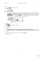
0 is represented as a 1 to the left, 1 as a 1 to the right. UNDEF and FLOAT are printed as xux
and xzx, respectively. prints at every time step. The output UNDEF 0 1 1 0 would be
printed as follows: xux 1 I-
-I 1
An example of its use is: (m=WAVEOUT)(n=waveout)(i=ol)(s=l);
SEE ALSO
gen(3) generic(3) ttl(3) simview(1) n&mod(l) THOR(l)
56
(2)
self-sched ( 3 )
THOR USER’S MANUAL
self-sched ( 3 )
NAME
self-sched , self-unsched - schedule a model for evaluation
SYNOPSIS
#include “mode1.h”
self-sched(delta-time,priority)
int delta-time , priority;
self-unsched(abs-time)
int abs-time;
A model can schedule itself to be evaluated at some future time using self_sched. The model will be
evaluated delta-time time units in the future. delta-time must be greater than zero.
priority can be either SELF0 or SZXFl. The former indicates that the model will be evaluated at the
beginning of the time period, and the latter indicates that it will be evaluated at the end of the time
period, after the rest of the network has reached steady state. These are defined in mud&z. Note that
mde2.h is included automatically by mhod(l).
Generator models normally use SELF0 and monitor models normally use SELFI.
self unsched will deschedule an evaluation. abs time is the absolute time at which the evaluation was
scheduled. Current time can be accessed via the external variable current-time. self_sched and
self~unsched return 0 for success and -1 for failure.
FTLES
model. h
SEE ALSO
mname(3), current_time(3), mkmod( l), THOR( 1)
AUTHORS
Beverly Vellandi
Henry Vellandi
University of Colorado, Boulder
May 1985
57
(1)
tW)
THOR USER’S MANUAL
W3)
NAME
ttl - ttl models available
SYNOPSIS
(f=modelname)(n=username)(i=inputs)(o=outputs)(s=states);
modelname is one of:
x x 0 4 xxlOxxl1 x x 2 7 xx30
xx00 xx02
xx74xx74ab xx76ab xx85
x x 3 2 x x 5 4 xx73ab
xxl09abxxl09b xxll2abxxll2b x x 1 3 8 xxl39ab
xx86
xx150 xx151 xx152 xx153 ~~155~x156
xx148
xx161 xx163 xx164 xx169 xx174 xx175
xx157
xx195 xx198 xx240 xx240ab xx241 xx24la xx24lb
xx244 xx244ab xx245 xx251 xx257 xx273 xx280
xx283 xx373 xx374 xX378 Xx379 xx541 xx576
xx874 xx874ab
xx869
xx580 ~~82~114
The THOR ttl models are described below. They are all specified with the (f=modeIname)...
construction in CSL, as indicated above. Some of the models require states as indicated. Use the
(do=...) construction of CSL to set delays. Otherwise, they are set to default value 1 by CIO(l). For
more information see the THOR tutorial.
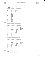
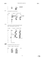
xx00
Quad 2-input NAND gate
8 inputs
index
0
1
2
3
4
5
6
7
8
4 outputs
input
8
1A
1B
2A
2B
3A
3B
4A
4B
0 internal states
output
4
1Y
2Y
3Y
4Y
states
0
xx04
hex inverter
6 inputs
index
1
2
3
4
5
6
6 outputs
input
Dl
D2
D3
D4
DS
D6
0 internal states
output
DlD2^
D3^
D4”
DS^
D6^
xxl09ab
J-K positive-edge-triggered Flip-flop w/ preset & clear
5 inputs
index:
2 outputs
input:
2 internal states
output:
58
(1 >
THOR USER’S MANUAL
tW)
1
2
3
4
5
PRE
J
W3)
last_CK
Q
Q
Q
Clk
K
CLR
xxl09b
J-K positive-edge-triggered Flip-flop w/ preset & clear
5 inputs
in&x:
1
2
3
4
5
2 outputs
input:
PR
CK
KA
J
CLR
2 internal states
output:
Q
Q
state:
last_CK
Q
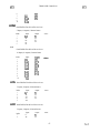
xx11
Triple 3-input positive-AND gates
0 internal states
3 outputs
9 inputs
index
1
2
3
4
input
al
bl
cl
output
Yl
Y2
Y3
a2
5
b2
6
7
8
9
c2
a3
b3
c3
xx1 12ab
J-K negative-edge-triggered Flip-flop w/ preset & clear
5 inputs
2 outputs
2
input:
PRE^
J
3
Clk
4
5
K
CLR*
index:
1
2 internal states
output:
Q
Q-
state:
last CK
Q -
xxll2b
J-K negative-edge-triggered Flip-flop w/ preset & clear
5 inputs
index:
1
2
3
4
2 outputs
input:
PR
J
K
CK
2 internal states
output:
QA
Q
state:
last_CK
Q
59
(2)
tW)
THOR USER’S MANUAL
5
CLR
W3)
-
xx138
3-to-8 line Decoder/Demul tiplexer
6 Inputs, 8 Outputs, 0 Internal States
index
1
2
3
4
5
6
7
8
input output
YO
B
Yl
Y2
C
Cl
Y3
GA2a Y4
G-2B
Y5
Y6
Y7
A
xx139ab
2-to-4 line Decoder/Demul tiplexer
3 Inputs, 4 Outputs, 0 Internal States
in&x
1
2
3
4
input output
A
YO
B
Yl
G
Y2
Y3
xx148
8-to-3 priority encoder
9 inputs
index
1
2
3
4
5
6
7
8
9
5 outputs
input
EI
Do
Dl
D2
D3
D4
D5
D6
D7
0 internal states
output
GS
EO
A0
Al
A2
xx150
16-to- 1 data selectors/multiplexers
21 inputs
index
1
2
3
4
5
1 outputs
input
STROBE
A
B
C
D
0 internal states
output
W
60
(3)
THORUSER'SMANUAL
W3)
6
7
EO
8
E2
E3
9
El
10
11
E4
E5
12
13
E6
14
15
16
17
18
19
20
21
E7
E8
E9
El0
El1
El2
El3
El4
El5
xx151
8-to-1 data selectors/multiplexers
2 outputs
12 inputs
in&x
1
2
3
4
input
STROBE
A
7
8
D3
9
10
11
12
D4
D5
D6
D7
6
output
Y
W
B
C
Do
Dl
D2
5
0 internal states
xx152
8-to-1 data selectors/multiplexers
11 inputs
index
1
2
3
4
5
6
7
8
9
10
11
1 outputs
input
A
B
C
DO
Dl
D2
D3
D4
D5
D6
D7
0 internal states
output
W
61
i
THOR USER’S MANUAL
tU3)
W3)
xx153
Dual 4-to- 1 data selectors/mu1 tiplexers
12 inputs
in&x
1
2
3
4
5
6
7
8
9
10
11
12
2 outputs
input
A
B
1G
1co
1Cl
lC2
lC3
2G
2co
2Cl
2c2
2C3
0 internal states
output
1Y
2Y
xx161
4 bit binary counter with asynchronous reset.
9 Inputs
index
1
2
3
4
5
6
7
8
9
5 outputs
2 Internal States
input
CLR
LOAD*
ENT
ENP
output
RCO
Clk
Qd
Qa
Qb
State
lst_CK
Old-Q
Qc
A
B
C
D
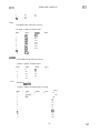
xx163
4 bit binary counter with synchronous reset.
9 Inputs
in&x
1
2
3
4
5
6
7
8
9
5 outputs
2 Internal States
input
CLRLOAD
ENT
ENP
output
RCO
CIk
Qd
Qa
Qb
State
lst-CK
Old-Q
Qc
A
B
C
D
xx164
8-bit Parallel-out Serial shift register
(positive edge triggered)
62
(5 >
THOR USER’S MANUAL
W3)
4 inputs
in&x:
1
2
3
4
5
6
7
8
9
9 internal states
8 outputs
input:
CLR^
Clk
A
B
output
states:
QA
QB
Ql
42
43
w
QD
QE
QF
Q5
46
w
47
44
QH
Q8
LAST-CLK
xx169
4 bit up/down synchronous binary counter
9 Inputs
in&x
1
2
3
4
5
6
7
8
9
5 outputs
input
LOADU/DENT
ENP
Clk
2 Internal States
output
RCO
Qa
Qb
State
lst_CK
Old-Q
Qc
Qd
A
B
C
D
xx174
Hex D-type Flip-Flop with clear (positive edge-triggered)
8 inputs
6 outputs
4
5
input
CLR
CK
Dl
D2
D3
6
Ix
7
8
D5
D6
index
1
2
3
7 internal states
outputs
Ql
Q2
43
44
Q5
46
state
last-ck
last-Q1
las t-Q2
last-Q3
last-Q4
last-Q5
last-Q6
xx175
quadruple D-type Flip-Flop with clear (positive edge-trigger-red)
6 inputs
index
1
2
3
4
8 outputs
input
CLR
CK
Dl
D2
5 internal states
outputs
Ql
Ql*
42
Q2*
state
last-ck
last-Q1
las t-Q2
last-Q3
63
W3)
W3)
THOR USER’S MANUAL
D3
Ix
5
6
7
8
WV
last-Q4
Q3
Q3*
44
w*
xx195
4-bit Parallel-access shift register
9 inputs
5 outputs 5 internal states
state:
las t_CK
input:
output:
SHIFT/LOAD^ Q a
CLR^
Qb
Clk
Qc
J
Qd
K
w
in&x:
1
2
3
4
5
6
7
Qa
Qb
Qc
Qd
b
8
C
9
d
xx198
S-bit Parallel in/out Serial left/right shift register
positive edge triggered, negative clear
8 outputs 9 internal states
14 inputs
index:
1
2
3
4
5
6
7
8
9
10
11
12
13
14
states:
output
input:
CLR
QA
so
QB
sl
w
CLK
QD
SR (serial rt) QE
A
QF
B
QG
c
-.
Ql
Q2
43
44
Q5
46
47
Q8
QH
D
E
F
G
H
SL (serial It)
LAST-CLK
xx240
Octal Buffers/line drivers/line receivers
10 inputs, 8 outputs, 0 internal states
in&x:
1
2
3
4
5
input:
1G
1Al
lA2
lA3
lA4
output:
1Yl
lY2
lY3
lY4
2Yl
states:
64
(7 1
W3)
THOR USER’S MANUAL
6
7
8
9
10
2G
2Al
2A2
2A3
2A4
W3)
2y2
2Y3
2Y4
xx240ab
Octal Buffers/line drivers/line receivers
5 inputs, 4 outputs, 0 internal states
in&x:
1
2
3
4
5
input:
Gl
Al
A2
A3
A4
output:
Yl
Y2
Y3
Y4
states:
xx241
Octal Buffers/line drivers/line receivers
10 inputs, 8 outputs, 0 internal states
index:
1
2
3
4
5
6
7
8
9
10
input:
1G
1Al
lA2
lA3
lA4
2G
2Al
2A2
2A3
2A4
output:
1Yl
1Y2
lY3
1Y4
2Y1
2Y2
2Y3
2Y4
xx241a
Octal Buffers/line drivers/line receivers
5 inputs, 4 outputs, 0 internal states
index:
1
2
3
4
5
input:
GA
Al
A2
A3
output:
Yl
Y2
Y3
Y4
states:
A4
xx241b
Octal Buffers/line drivers/line receivers
5 inputs, 4 outputs, 0 internal states
index:
1
2
input:
G
Al
output:
Yl
Y2
states:
65
(8)
THOR USER’S MANUAL
tW)
A2
A3
A4
3
4
5
tW)
Y3
Y4
xx244
Octal Buffers/line drivers/line receivers
10 inputs, 8 outputs, 0 internal states
index:
1
2
3
4
5
6
7
8
9
10
input:
lG^
1Al
lA2
lA3
lA4
2G
2Al
2A2
2A3
2A4
states:
output:
Yll
Y12
Y13
Y14
Y21
Y22
Y23
Y24
xx244ab
Octal Buffers/line drivers/line receivers
5 inputs, 4 outputs, 0 internal states
index:
1
2
3
4
5
input:
G
Al
A2
A3
A4
states:
output:
Yl
Y2
Y3
Y4
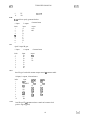
xx245
Octal bus tranceiver
2 inputs, 0 outputs, 0 internal states, 16 biputs
index:
0
1
2
3
4
5
6
7
8
input:
2
ENABLE
biput:
16
Al
A2
A3
A4
A5
A6
A7
A8
Bl
B2
B3
B4
state:
output:
0
0
DIR
9
10
11
12
66
(9)
THOR USER’S MANUAL
W3)
WV
BS
B6
B7
B8
13
14
15
16
17
18
Quadruple 2-line-to-l-line data selectors/multiplexers
index
1
2
3
4
5
6
7
8
9
10
0 internal states
4 outputs
10 inputs
input
output
G (output control)
1Y
2Y
S (select A/B)
3Y
1A
4Y
1B
2A
2B
3A
3B
4A
4B
xx27
triple 3-input positive NOR gates
3 output
0 internal states
9 inputs
index
input
output
al
bl
cl
a2
Yl
Y2
Y3
b2
c2
a3
b3
c3
xx273
Octal D-type Flip-Flop with common clock & clear
(positive edge-triggerred)
10 inputs, 8 outputs, 9 internal states
index:
1
2
3
4
5
6
7
8
input:
CLR
elk
Dl
D2
D3
D4
D5
D6
output:
Ql
Q2
states:
Ql
42
Q3
44
Q5
Q6
Q7
Q8
Q3
Q4
Q5
Q6
Q7
Q8
67
ho 1
THOR USER’S MANUAL
WV
9
10
W3)
last_CK
D7
D8
xx280
g-bit odd/even parity generator/checker
9 inputs
in&x
1
2
3
4
5
6
7
8
9
2 outputs
input
A
B
C
D
E
F
0 internal states
output
even
odd
G
H
I
xx32
Quad 2-input OR gate
8 inputs
index
1
2
3
4
5
6
7
8
4 outputs
input
la
lb
2a
2b
3a
3b
4a
4b
0 internal states
output
Yl
Y2
Y3
Y4
xx373
Octal D-type Latch with common output control & common enable
10 inputs, 8 outputs, 8 internal states
index:
1
2
3
4
5
6
8
9
10
input:
ocA
ENABLE
Dl
D2
D3
D4
D5
D6
D7
D8
output:
Ql
42
Q3
w
Q5
Q6
Q7
QS
states:
Ql
42
Q3
Q4
Q5
Q6
Q7
Q8
xx374
Octal D-type FF w/ common tristate control and common clock
(positive edge triggered)
68
(11)
tW)
THOR USER’S MANUAL
9 internal states
8 outputs
10 inputs
index:
1
2
3
Clk
5
6
7
I34
D5
8
D6
D7
D8
4
9
10
states:
Ql
42
output:
Ql
42
input:
CNTRL
Dl
D2
D3
tw31
43
43
44
44
Q5
Q5
46
47
Q8
LST-CLK
Q6
47
48
xx378
Six D-TYPE Flip-Flops with Common Clock and Enable
8 inputs
in&x
0
1
2
3
4
5
6
7
8
6 outputs
7 internal states
output
6
Ql
42
43
44
Q5
46
input
8
G
CLK
Dl
D2
D3
D4
D5
D6
7
Ql
42
43
44
Q5
46
1astJk
xx379
Quad D-TYPE Flip-Flops
8 outputs
6 inputs
in&x
0
1
2
3
4
5
6
7
8
5 internal states
output
input
6
states
5
8
G
CLK
Dl
D2
Ql
QlQ2
42-
D3
D4
Q3
Q3*
Ql
Q2
Q3
44
last-elk
44
Q4^
74LS54
4-wide AND-OR-INVERT gates
10 inputs
index
1
2
1 output
input
A
B
0 internal states
output
Y
69
(12 >
THOR USER’S MANUAL
tW)
3
4
5
6
7
8
9
10
WV
C
D
E
F
G
H
I
J
xx541
Octal Buffers/line drivers with t&state outputs
10 inputs, 8 outputs, 0 internal states
in&x:
1
2
3
4
5
6
7
8
9
10
input:
1G
2GA
Al
A2
A3
A4
A5
A6
A7
A8
output:
Yl
states:
Y2
Y3
Y4
Y5
Y6
Y7
Y8
xx576
Octal D-type FF w/ common t&ate control, common clock,
positive edge triggered, inverted outputs
10 inputs
index:
1
2
3
4
5
6
7
8
9
10
8 outputs
input:
CNTRL
Clk
Dl
D2
D3
D4
D5
D6
D7
DS
9 internal states
output:
QIA
42
Q3^
w*
Q5^
46
Q7^
Q8^
states:
Ql
42
43
44
QS
46
47
Q8
LST-CLK
xx580
Octal D-type Latch with common output control & common
enable and inverted outputs
10 inputs, 8 outputs, 8 internal states
index:
1
2
3
input:
oc
ENABLE
Dl
output:
Ql’Q2
Q3^
states:
Ql
Q2
43
70
(13 >
WV
THOR USER’S MANUAL,
4
5
6
7
D2
D3
D4
D5
w
Q5^
46
44
8
D6
Q7^
Q7
QSA
Q8
9
10
D7
D8
W3)
Q5
46
xx74
Dual D-type pos-edge triggered flip-flop w/ preset & clear
8 inputs
in&x:
1
2
3
4
5
6
7
8
4 internal states
4 outputs
input:
1PFw
lclk
1D
lCLRA
2PRE^
2clk
2D
2CLR^
output
Ql
Ql42
42
state:
last_CK 1
Ql
last-cK2
42
xx74ab
Dual D-type pos-edge triggered flip-flop w/ preset & clear
4 inputs
index:
1
input:
PRE
2
3
CLK
4
2 internal states
2 outputs
output:
Q
Q
state:
last CK
Q-
D
CLR
xx76ab
J-K positive level sense J-K Flip flop w/ preset & clear
Note: xx76”ab” models one of the 2 J-K flip flops in xx76
5 inputs
index:
1
2
3
4
5
1 internal states
2 outputs
input:
PRE
J
output:
Q
Q
state:
last-Q
Clk
K
CLR-
xx85
4 bit magnitude comparitor
(NOTE: L85 requires different model.)
11 Inputs, 3 Outputs, 0 States
index
1
input output
A<B
A0
71
(
14
)
tuw
THOR USER’S MANUAL
2
3
4
5
6
7
8
9
10
11
Al
A2
A3
A<B
A=B
A>B
BO
Bl
B2
B3
A=B
A>B
xx86
Quad 2-input XOR gates
8 inputs
in&x
0 internal states
4 outputs
input
8
1A
1B
2A
2B
3A
3B
4A
4B
output
states
0
4
1Y
2Y
3Y
4Y
xx874ab
octal D-type FF w/ common tristate control (per each l/2),
common clock (per each l/2), & common clear- (per each l/2)
(positive edge triggered)
7 inputs
in&x:
1
2
3
4
5
6
7
4 outputs
5 internal states
input:
output:
CNTRLelk
CLR”
Dl
D2
D3
D4
Ql
Q2
43
44
states:
Ql
42
43
w
last-elk
xx874ab
l/2 of octal D-type FF w/ common tristate control,
common clock, and common clearA
(positive edge triggered)
7 inputs
index:
1
4 outputs
input:
CNTRL
5 internal states
output:
Ql
states:
Ql
72
tfw)
THOR USER’S MANUAL
W3)
2
3
4
5
6
7
42
Clk
CLR^
Q344
Dl
42
43
44
last-elk
D2
D3
D4
SEE ALSO
mon(3) gen(3) generic(3) n&mod(l) THOR(l) cio( 1)
73
UNIX Programmer’s Manual
vand( 3)
vand(3)
NAME
vandun - vector AND, two input AND table
SYNOPSIS
#include “vec.h”
extem int vand[][];
DESCRIF’TION
Performs the boolean AND operation by a table look-up approach, using two integer logic values as
indices. Equivalent to a 2-input AND gate. The logic values must be elements of the integer set (0, 1,
2, 3) corresponding to the logic values {ZERO, ONE, UNDEF, FLOAT}. The two dimensional integer
array is defined as:
ire vand[4][4] =
{
{w,o,o~~
1.
/* 2-input AND gate */
(O,l WI,
{W,W,
{W,2,21
INCLUDE FILE
vec.h - file containing extem definition.
ARCHIVE LIBRARY
generic .a
SEE ALSO
vand(3), vfah(3), vmv(3), vmap(3), vnand(3), vnor(3), vor(3), vrise(3), vtbuf(3), vtbufi(3), vtgate(3),
vxnor(3), vxor(3)
CAVEATS
The integer indices is restricted to the set of integers {0,1,2,3}.
AUTHOR
Ernest J. Frey
74
(1 >
vectors ( 3 )
UNIX Programmer’s Manual
vectors ( 3 )
NAME
vectors - vector functions (tible look-up) variables
SYNOPSIS
#include “vec.h”
$THOR/lib/generic.a
DESCRIPTION
Various vector functions, or table look-up variables, are available to all ‘C’THOR models. All vector
functions &fine some logic operation using a table look-up approach where the indices into the table
are integer logic values. The logic values must be elements of the integer set (0, 1, 2, 3)
corresponding to the logic values {ZERO, ONE, UNDEF, FLOAT}. All such vector functions are
defined and contained in the archive library, $THORllib/generic.a. The ‘C’ extem definitions are found
in $THORlincZude/vec.h. They are treated in ‘C’ THOR models as global integer arrays. All available
supported vector functions are described in the manual pages of section vector.
INCLUDE FILE
vec.h - file containing extem definition.
ARCHIVE LIBRARY
generic.a
SEE ALSO
vand(3), vfall(3), vinv(3), vmap(3), vnand(3), vnor(3), vor(3), vrise(3), vtbuf(3), vtbufi(3), vtgate(3),
vxnor(3), vxor(3)
AUTHOR
Ernest J. Frey
75
(1)
.
UNIX Programmer’s Manual
vfall( 3)
vfall(3)
NAME
vfall[][] - vector falling-edge detection
SYNOPSIS
#include “vec.h”
extem int vfall[][];
DESCRIPTION
Used to detect falling-edges by a table look-up approach, using two integer logic values as indices. The
first index is the old logic value and the second index is the new logic value. For example,
vfall[oldck][ck]. In a ‘C’ model, the old logic value is usually stored in an internal state. The logic
values must be elements of the integer set (0, 1, 2, 3) corresponding to the logic values {ZERO, ONE,
UNDEF, FLOAT}. The two dimensional integer array is defined as:
int vfall[4][4] =
{
/* edge-detection array */
/* new ck */
*I
/* old ck */ { 0, 0, 0, 0}, /* 0 = no fall
{ 1, 0,-1,-l}, /* 1 = fall
*I
{-I, 0,-1,-l), /* -1 = potential fall */
(-1, 0,-1,-l}
1;
INCLUDE FILE
vec.h - file containing extem definition.
ARCHIVE LIBRARY
generic-a
SEE ALSO
vand(3), vinv(3), vmap(3), vnand(3), vnor(3), vor(3), vrise(3), vtbuf(3), vtbufi(3), vtgate(3), vxnor(3),
vxor(3)
CAVEATS
The integer indices is restricted to the set of integers {0,1,2,3}.
AUTHOR
Ernest J. Frey
76
UNIX Programmer’s Manual
vinv(3)
vinv(3)
NAME
vinv[J - vector INV, one input INV table
SYNOPSIS
#include “vec.h”
extem int vinv[];
DESCRIPTION
Performs the boolean INV (NOT) operation by a table look-up approach, using an integer logic value as
an index. Equivalent to a single input INVERTER gate. The logic values must be elements of the
integer set (0, 1, 2, 3) corresponding to the logic values {ZERO, ONE, UNDEF, FLOAT}. The onedimensional integer array is defined as:
int vinv[4] =
L
1.
/* l-input INVERTER gate */
c 1 ,wa
INCLUDE FILE
vec.h - file containing extern definition.
ARCHIVE LIBRARY
generic .a
SEE ALSO
vand(3), vfaQ3), vmap(3), vnand(3), vnor(3), vor(3), vrise(3), vtbuf(3), vtbufi(3), vtgate(3), vxnor(3),
vxor( 3)
CAVEATS
The integer index is restricted to the set of integers {0,1,2,3}.
AUTHOR
Ernest J. Frey
77
(1 >
UNIX Programmer’s Manual
VmapW
vnw(3)
NAME
vmapo - vector MAP, one input MAP table
SYNOPSIS
#include “vech”
extem int vmap[];
DESCRIPTION
Performs the boolean identity operation by a table look-up approach, using an integer logic value as an
index, Equivalent to a single input NON-INVERTING gate; however, a FLOAT is mapped into an
UNDJZF. The logic values must be elements of the integer set (0, 1, 2, 3) corresponding to the logic
values {ZERO, ONE, UNDEP, FLOAT}. The one-dimensional integer array is defined as:
int vmap[4] =
L
/* l-input non-inverting gate */
(0, LW
INCLUDE FILE
vech - file containing extem definition.
ARCHIVE LIBRARY
generic.a
SEE ALSO
vand( 3), vfall( 3), vinv(3), vnand( 3), vnor(3), vor(3), vrise(3), vtbuf(3), vtbufi(3), vtgate(3), vxnor(3),
vxor( 3)
CAVEATS
The integer indices is restricted to the set of integers {0,1,2,3}.
AUTHOR
Ernest J. Frey
78
(1)
.
UNIX Programmer’s Manual
vnand(3)
vnand(3)
NAME
vnand[] fl - vector NAND, two input NAND table
SYNOPSIS
#include “vech”
extern int vnand[][];
DESCRIPTION
Performs the boolean NAND operation by a table look-up approach, using two integer
logic values as
indices. Equivalent to a 2-input NAND gate. The logic values must be elements of the integer set (0,
1, 2, 3) corresponding to the logic values {ZERO, ONE, UNDER, FLOAT}. The two dimensional
integer array is defined as:
int vnand[4][4] =
1
{LLW,
c 1 ,w,21,
/* 2-input NAND gate *(I/
CLW,21,
{ 12,wl
INCLUDE FILE
vec.h - file containing extem definition.
ARCHIVE LIBRARY
generic.a
SEE ALSO
vand(3), vfdl(3), vinv(3), vmap(3), vnor(3), vor(3), vrise(3), vtbuf(3), vtbufi(3), vtgate(3), vxnor(3),
vxor( 3)
CAVEATS
The integer indices is restricted to the set of integers {0,1,2,3}.
AUTHOR
Ernest J. Frey
79
(1 >
UNIX Programmer’s Manual
vnor(3)
vnor(3)
NAME
vnor[][] - vector NOR, two input NOR table
SYNOPSIS
#include “vec.h”
extem int vnor[][];
DESCRIPTION
Performs the boolean NOR operation by a table look-up approach, using two integer logic values as
indices. Equivalent to a 2-input NOR gate. The logic values must be elements of the integer set (0, 1,
2, 3) corresponding to the logic values {ZERO, ONE, UNDER, FLOAT}. The two dimensional integer
array is defined as:
int vnor[4][4] =
/* 2-input NOR gate */
i
W,2,2),
um0901~
W,2,2},
cw2,21
1;
INCLUDE FILE
vec.h - file containing extem definition.
ARCHIVE LIBRARY
generic.a
SEE ALSO
vand(3), vfall(3), vinv(3), vmap(3), vnand(3), vor(3), vrise(3), vtbuf(3), vtbufi(3), vtgate(3), vxnor(3),
vxor(3)
CAVEATS
The integer indices is restricted to the set of integers {0,1,2,3}.
AUTHOR
Ernest J. Frey
80
(1)
UNIX Programmer’s Manual
vor(3)
vor(3)
NAME
voro[] - vector OR, two input OR table
SYNOPSIS
#include “vech”
extem int voro[];
DESCRIPTION
Performs the boolean OR operation by a table look-up approach, using two integer logic values as
indices. Equivalent to a 2-input OR gate, The logic values must be elements of the integer set (0, 1,
2, 3) corresponding to the logic values {ZERO, ONE, UNDEF, FLOAT}. The two dimensional integer
array is defined as:
int vor[4] [4] =
L
/* 2-input OR gate */
cw,w,
~LLLll,
CT LUI,
P,1,Wl
1;
INCLUDE FILE
vec.h - file containing extem definition.
ARCHIVE LIBRARY
generic .a
SEE ALSO
vand(3), vfall(3), vinv(3), vmap(3), vnand(3), vnor(3), vrise(3), vtbuf(3), vtbufi(3), vtgate(3), vxnor(3),
vxor(3)
CAVEATS
The integer indices is restricted to the set of integers (0,1,2,3}.
AUTHOR
Ernest J. Frey
81
UNIX Programmer’s Manual
vrise( 3)
vrise(3)
NAME
vrise[][] - vector rising-edge detection
SYNOPSIS
#include “vet. h”
extem int vrise[][];
DESCRIPTION
Used to detect rising-edges by a table look-up approach, using two integer logic values as indices. The
first index is the old logic value and the second index is the new logic value. For example,
vrise[oldck][ck]. In a ‘C’ model, the old logic value is usually stored in an internal state. The logic
values must be elements of the integer set (0, 1, 2, 3) corresponding to the logic values {ZERO, ONE,
UNDEF, FLOAT}. The two dimensional integer array is defined as:
int vrise[4][4] 3.
/* edge-detection array */
/* new ck *I
*I
/* old ck */ { 0, 1,-1,-l}, /* 0 - no rise
*I
{ 0, 0, 0, 0}, /* 1 = rise
{ 0,-1,-1,-l}, /* -1 = potential rise */
{ 0,-1,-1,-l}
I;
{
INCLUDE FILE
vec.h - file containing extem definition.
ARCHIVE LIBRARY
generic.a
SEE ALSO
vand(3), vfall(3), vinv(3), vmap(3), vnand(3), vnor(3), vor(3), vtbuf(3), vtbufi(3), vtgate(3), vxnor(3),
vxor( 3)
CAVEATS
The integer indices are restricted to the set of integers {0,1,2,3}.
AUTHOR
Ernest J. Frey
82
(1>
UNIX programmer’s Manual
vtbuf( 3)
vtbuf ( 3 )
NAME
vtbufn[] - vector non-her&g t&state buffer
SYNOPSIS
#include “vech”
extem int vtbuf[][];
DESCRIPTION
Equivalent to a single-input single-output non-inverting &i-state buffer with active high enable.
Performs this n-i-state buffer operation by a table look-up approach, using two integer logic values as
indices. The first index is the enable and the second index is the data.
For example, vtbufI enable ][ data 1. The logic values must be elements of the integer set (0, 1, 2, 3)
corresponding to the logic values {ZERO, ONE, UNDEF, FLOAT}. The two dimensional integer array
is defined as:
/* ttistate non-inverting buffer */
int vtbuf[4][4] =
/* vtbuf[en][dat] */
{ /* &i-input */
/* tri enable*/ {3, 3, 3, 3},
(0, 1, 2, 21,
c& 2, 2, 219
cz 2, 2, 21
INCLUDE FILE
vec.h - file containing extem definition.
ARCHIVE LIBRARY
generic.a
SEE ALSO
vand(3), vfall(3), vinv(3), vmap(3), vnand(3), vnor(3), vor(3), vrise(3), vtbufi(3), vtgate(3), vxnor(3),
vxor(3)
CAVEATS
The integer indices are restricted to the set of integers {0,1,2,3}.
AUTHOR
Ernest J. Frey
83
(1>
UNIX Programmer’s Manual
vtbufi ( 3 )
vtbufi (3 )
NAME
vtbufin[] - vector inverting t&state buffer
SYNOPSIS
#include “vec.h”
extern int vtbufi[][];
DESCRIPTION
Equivalent to a single-input single-output inverting t&ate buffer with active high enable. Performs
this t&state buffer operation by a table look-up approach, using two integer logic values as indices.
The first index is the enable and the second index is the data.
For example, vtbufi[ enable ][ data 1. The logic values must be elements of the integer set (0, 1, 2, 3)
corresponding to the logic values {ZERO, ONE, UNDEF, FLOAT}. The two dimensional integer array
is defined as:
/* tristate inverting buffer */
int vtbufi[4][4] =
/* vtbufi[en][dat] */
( /* t&input */
/* tri enable*/ {3, 3, 3, 3},
CL 0, 2, 21,
{Z 2, 2, 21,
KS 2, 2, 21
I;
INCLUDE FILE
vec.h - file containing extem definition.
ARCHIVE LIBRARY
generic .a
SEE ALSO
vand(3), vfall(3), vinv(3), vmap(3), vnand(3), vnor(3), vor(3), vrise(3), vtbuf(3), vtgate(3), vxnor(3),
vxor(3)
CAVEATS
The integer indices is restricted to the set of integers {0,1,2,3}.
AUTHOR
Ernest J. Frey
84
(1)
vtgaW3)
UNIX Programmer’s Manual
vtgate ( 3 )
NAME
vtgate[]u - vector “transmission” gate
SYNOPSIS
#include “vec.h”
extem int vtgate[Jn;
DESCRIPTION
Equivalent to a CMOS transmission gate with complementary enables. The “output” of this gate is a
ONE if the gate is enabled, a ZERO if the gate is disabled, and UNDEF otherwise. Performs this
operation by a table look-up approach, using two integer logic values as indices. The first index is the
active-low enable and the second index is the active-high enable. For example, vtgate[ enA ][ en 1.
This function was developed to control the enable signal of a vbufl][] or vtbufi[][] to build a polycell
t&state buffer, i.e. vbuf[ vtgate[en*][en] ][ data 1. The logic values must be elements of the integer set
(0, 1, 2, 3) corresponding to the logic values {ZERO, ONE, UNDEF, FLOAT}. The two dimensional
integer array is defined as:
/* CMOS “transmission” gate w/ complementary enables */
int vtgate[4][4] =
/* enable */
I* vtgate[en^][en] */
1
/* enable”*/ (1, 1, 1, 1)
10, 1, 2, 21,
P, 1, 2, 21,
cz 1, 2, 21
1;
INCLUDE FILE
vec.h - extem definition file.
ARCHIVE LIBRARY
generic.a
SEE ALSO
vand(3), vfall(3), vinv(3), vmap(3), vnand(3), vnor(3), vor(3), vrise(3), vtbuf(3), vtbufi(3), vxnor(3),
vxor( 3)
CAVEATS
The indices are restricted to the integer set {0,1,2,3}.
AUTHOR
Ernest J. Frey
85
( 1>
THOR 3.0
vxnor ( 3 )
vxnor ( 3 )
NAME
vxnorfl[J - vector XNOR, two input XNOR table
SYNOPSIS
#include “vec.h”
extem int vxnor[]n;
DESCRIPTION
Performs the boolean XNOR operation by a table look-up approach, using two integer logic values as
indices. Equivalent to a 2-input XNOR gate. The logic values must be elements of the integer set (0,
1, 2, 3) corresponding to the logic values {ZERO, ONE, UNDEF, FLOAT}. The two dimensional
integer array is defined as:
int vxnor[4][4] =
L
1.
I* 2-input EXCLUSIVE-NOR gate */
w,w,
w,w,
{W,W,
v,22,21
INCLUDE FILE
vec.h - file containing extem definition.
ARCHIVE LIBRARY
generica
SEE ALSO
vmd(3), vfall(3), vhv(3), vmap(3), vnand(3), vnor(3), vor(3), vrise(3), vtbuf(3), vtbufi(3), vtgate(3),
vxor(3)
CAVEATS
The integer indices is restricted to the set of integers {0,1,2,3}.
AUTHOR
Ernest J. Frey
86
UNIX Programmer’s Manual
vxor(3)
vxor( 3)
NAME
vxornn - vector XOR, two input XOR table
SYNOPSIS
#include “vec.h”
extem int vxor[][];
DESCRIPTION
Performs the boolean XOR operation by a table look-up approach, using two integer logic values as
indices. Equivalent to a 24nput XOR gate. The logic values must be elements of the integer set (0, 1,
2, 3) corresponding to the logic values {ZERO, ONE, UNDEF, FLOAT}. The two dimensional integer
array is defined as:
int vxor[4][4] =
L
1;
/* 2-input EXCLUSIVE-OR gate */
m1,zn
c ~,W,21,
{2,2,Wl,
(ZZW
INCLUDE FILE
vec.h - file containing extem definition.
ARCHIVE LIBRARY
generic .a
SEE ALSO
vand(3), vfall(3), vinv(3), vmap(3), vnand(3), vnor(3), vor(3), v&e(3), vtbuf(3), vtbti(3), vtgate(3),
vxnor( 3)
CAVEATS
The integer indices is restricted to the set of integers {0,1,2,3}.
AUTHOR
Ernest J. Frey
87
simint ( 5 )
Integrated testing using THOR
simint(5)
OVERVIEW
For most VLSI designs, it is -useful to first model the logic function with functional simulation. Later,
when all or part of the &sign has been converted to a less abstract level, a consistency check between
the two models can be extremely helpful. Previously, Ictest (developed at Stanford) has been used for
design verification. However, it is geared strictly for verification, The original functional model is
often of little use.
By providing an interface between Thor and other simulators, such as Rsim, the chip tester, or logic
analyzer, the Thor functional specification can be used to verify the design. While a true mixed-level
simulation has some advantages, it is not the best method for simply verifying a design. For this, it is
more useful to simulate the two different levels of design in parallel and check for discrepancies.
A master-slave relationship is established between Thor and the other simulator. As master, Thor controls the inputs to the slave, and tells when to check the outputs of the slave. Bidirectional nodes are
not as easy.
For biputs, there will be a set of elements driving at any moment. If all the drivers are within the set
of elements duplicated by the slave simulation, then the node is acting as an output. In this case, the
node will not be set, but may be checked. If any one of the drivers is outside the set, then the node is
assumed to be acting as an input. Now, the slave node is set to the Thor value.
In this scheme, some correspondence between Thor timing and that of the slave simulator must be
made. For working with Rsim, the mapping is nearly direct. Initially, both simulators work together in
time. However, if the user bypasses Thor and steps Rsim directly, an offset is created. This is handled
by making the extra time ‘free’. Thor does not try to catch up with Rsim, or wind it back in time.
Hence simulation continues with the offset.
The user interface has two facets: a map file and Thor commands. In use, Thor is run on the csl file for
the design as usual, using the interactive interface. Once inside Thor, the new commands can be used
to activate the slave simulator for testing.
New THOR
commands
Several commands and options have been added to interactive Thor to support this simulator interface.
Like all Thor commands, they may be abbreviated.
SIMULATE mapfile
SIMULATE
This command uses the mapfile to start up the proper simulator and builds the map between Thor nodes
and the pins of the other simulator. This map is used, initially, to properly set the inputs and biputs
(when they are driven by ‘external’logic). Output checking is specified separately. The simulate command, with no mapfile, allows the user begin working directly with the slave simulator. For example,
this can be used to ‘drop in’ to Rsim. This mode can be exited by typing a period (’ .‘) for the command.
CHECK node(s) clocking trigger-node
CHECK node(s)
CHECK
The check command is used to control when and which signals are checked between the <imulators.
The long form is used to add signals to be checked. The trigger-node supplies the timing I( )I \C hen to
check nodes. The clocking type ‘stable’ indicates that the given nodes be checked on hort~ 1 tit! rising
and falling edges of the trigger-node. The clocking ‘valid’ allows checking to only be I~C’I 14 )r-rned on
(1)
Integrated testing using THOR
simint ( 5)
simint ( 5 )
the falling edge of the trigger-node. To check on the rising edge of the trigger, ‘rising’ may be
specified for the clocking.
Multiple check commands may be given to check the same node at different times. The second form
of the check command allows checking for a node to be disabled. The current check list can be
displayed by a simple ‘check’ command with no arguments.
The Map File
The map file specifies the logical equivalence between Thor nodes and those of the slave simulator
(Rsim, chip tester, etc.). In addition, some simulator specific information may be given here. For
better or worse, the current syntax resembles a csl function call (but this is not csl!). The first item
gives the simulator name and any command line parameters needed. Next, the user specifies the Thor
instance name against which to test. Then, input, output, and biput sections specify the mapping
between the two models. The orientation is always ‘sim-name = Thor-node’.
Here is a short example, for a circuit which resembles an I/O pad.
(s = rsim, buf.rsm)
(n = bufl)
(inputs:
= ctll,
= inl)
in
(outputs:
out = outl)
(biputs:
bus = bus);
CtI
This allows the Rsim model, buf.rsm, to be checked. Its inputs are labeled ‘ctl’ and ‘in’, output is
‘out’, and biputs is ‘bus’. This will be checked against the Thor instance called ‘bufl ‘, which may be
either a model or subnetwork (both work with the same definition). The corresponding Thor names are
‘ctll’, ‘inl’, ‘outl’, and ‘bus’.
The description of the timing characteristics of each node is separated out, as that is expected to be
dependent on the Thor model only.
Sample Thor Session
gurgi% cat buftst.csl
/* generate stimulus */
(g=COUNT)(n=src)
(o=ctll,ctl2,inl,in2,phi_nl)
(s= l)(vs=S);
/* clock for checking */
(f=INV)(n=phibar)
(i=phi-n 1)
(o=phi-ql)(do=O);
(f=OR)(n=somedrive)
(i=ctll,ctl2)
(o=check)(do=O);
(f=AND)(n=checker)
(i=phi-q 1 ,check)
(o=check-ql)(do=O);
89
simint ( 5 )
Integrated testing using THOR
simint (5)
/* driver subnet */
(sub=driver)(i=ctl,i)(o=out)(b=bus)
i
(f=AND)(n=inbuf)(i=bus)(o=out)(do=l);
(f=TBUF)(n=outdrv)(i=ctl,in)(o=bus)(do=l);
I
(f=driver)(n=bufl)
(i=ctll,inl)
(o=outl)
(b=bus);
(f=driver)(n=buf’Z)
(i=ctl2,in2)
(o=out2)
(b=bus);
(m=BINOUT)(n=drl)(i=inl,ctll);
(m=BINOUT)(n=dr2)(i=in2,ctl2);
(m=BINOUT)(n=outs)(i=outl,out2,bus);
Use
the buf mapfile to equate rsim node names to thor net names.
gurgi% cat buf
6 = rsim, buf.rsm)
(n = bufl)
(inputs:
Ctl
= ctll,
in
= inl)
(outputs:
out = outl)
(biputs:
bus = bus);
Run thor interactively.
gurgi% gensim -i buftst.csI
/projeots/cad/bin/cio -d buftst -t cmos buftstcsl
cio: output #0 (check-ql) is unconnected on checker
/projects/cacVbin/ftable -m buftst
cc -I/projects/cad/lib/thor/include -0 buftst.exe
/projects/cad/lib/thor/mainsim.o buftst.c
/projects/cad/lib/t.bor/libarp.a /projects/cad/lib/thor/models.a
/projects/cad/lib/thor/thorlib.a /projects/cad/lib/thor/libarp.a
/projects/cad/lib/thor/models.a
buftst.exe -i > buftst.out
thor $ : o> sim buf
compare rsim model buf.rsm with thor bufl
thor $ : o> check out1 valid check-q1
thor $ : o> check bus valid check-q1
thor $ : o> check
90
(3)
simint ( 5 )
Integrated testing using THOR
simint(5)
check bus valid check-q1
check out1 valid check-q1
thor $ : o> go +150
thor $ : 150> sim
ninud*
in-b=0 out-b-X vdd-1 gnd-0 ctl-b=O out-X bus-dn=X in=1 bus=X bus-up-X c&=1
time - 145.Ons
rsinm ? bus
bus-X [NOTE: node is an input] (~1-0.4 vhrO.6) (0.021 pf) is computed from:
n-channel ctL1 bus-dn=X bus-X [6.Oe+O3, 1.2e+O4,6.Oe+O3]
p-channel ctl-b-0 bus-up=X bus-X [ 1.2e+O4, 1.2e+O4,2.4e+O4]
rsim>xbus
rsim>s8
time = 145.8ns
rsim>d*
in-b=0 out-b-0 vdd-1 gnd=O ctl-b=O out=1 bus+=1 in=1 bus=1 bus-up=1 ctl=l
time = 145.8ns
rsim> .
thor $ : 150> q
SEE ALSO
thor( 1) gensim( 1)
91
(4)