1
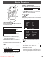
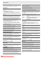
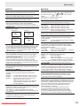
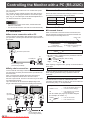
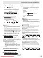
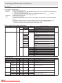
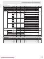
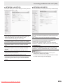
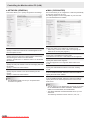
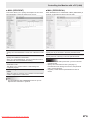
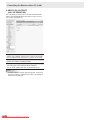
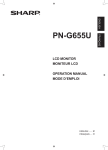
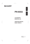
PN-S655
LCD MONITOR
OPERATION GUIDE
Downloaded From TV-Manual.com Manuals
Contents
Basic Operation................................................................3
Menu Items........................................................................5
Displaying the menu screen..........................................5
Menu item details..........................................................6
Adjustments for PC screen display.............................10
Initialization (Reset)/Functional Restriction Setting.... 11
Controlling the Monitor with a PC (RS-232C)...............12
PC connection.............................................................12
Communication conditions..........................................12
Communication procedure..........................................12
RS-232C command table............................................16
Controlling the Monitor with a PC (LAN)......................21
Settings to connect to a LAN.......................................21
Controlling with a PC...................................................23
This guide contains instructions regarding operation, settings, and similar details.
For instructions regarding connection and installation, refer to the included Operation Manual.
Manual Scope
- Microsoft, Windows and Internet Explorer are registered trademarks of Microsoft Corporation.
- HDMI, the HDMI Logo and High-Definition Multimedia Interface are trademarks or registered trademarks of HDMI Licensing
LLC.
- Adobe, Acrobat, and Reader are either registered trademarks or trademarks of Adobe Systems Incorporated in the United
States and/or other countries.
- This product comes with RICOH Bitmap Fonts produced and sold by RICOH COMPANY, LTD.
- All other brand and product names are trademarks or registered trademarks of their respective holders.
- Language of OSD menu used in this manual is English by way of example.
- Illustrations in this manual may not exactly represent the actual product or display.
2
E
Downloaded
From TV-Manual.com Manuals
Basic Operation
5. BRIGHT +/- (Backlight adjustment)
or
displays the BRIGHT menu when the
Pressing
menu screen is not displayed.
1
2
BRIGHT
3
4
15
Press
or
to adjust the brightness.
* If you do not press any buttons for about 4 seconds, the
BRIGHT menu automatically disappears.
5
6. SIZE (Screen size selection)
The menu is displayed.
Press
or
to select the screen size. (See page 4.)
6
7
7. DISPLAY
Displays monitor information. Every time you press this button,
the display changes from INFORMATION 1 →
INFORMATION 2 → display clear and so on.
8
INFORMATION 1
1. INPUT (Input mode selection)
or
to select the input
The menu is displayed. Press
mode, and press
to enter.
* You can select the input terminal by pressing the input
switch of the monitor.
Input mode
Video
PC1 DVI-D*1
PC1 input terminal
PC2 HDMI*2
PC2 input terminal
PC3 D-SUB
PC3 input terminal
PC4 RGB*3
PC4 input terminals
AV1 DVI-D*1
AV1 input terminal
AV2 HDMI*2
AV2 input terminal
AV3 COMPONENT*3
AV3 input terminals
AV4 S-VIDEO
AV4 input terminal
AV5 VIDEO
AV5 input terminal
Audio
PC audio input
terminal
AV audio input
terminals
*1 Select the terminal for DVI SELECT. (See page 7.)
*2 Select the terminal for HDMI SELECT. (See page 7.)
Select the terminal for HDMI AUDIO SELECT which is
used for audio input. (See page 7.)
*3 Select the terminal for BNC SELECT. (See page 7.)
2. MUTE
Turns off the volume temporarily.
Press the MUTE button again to turn the sound back to the
previous level.
3. MENU
Displays and turns off the menu screen (see page 5).
4. VOL +/- (Volume adjustment)
Pressing
or
displays the VOLUME menu when the
menu screen is not displayed.
VOLUME
15
XXXX/XX/XX XXX
INPUT MODE
:
PC3 D-SUB
SIZE
:
WIDE
COLOR MODE
:
STD
BRIGHT
:
15
VOLUME
:
15
ID No.
:
0
MODEL
:
PN-S655
S/N
:
STATUS
:
LAN
1920x1080
V: 60 Hz
INFORMATION 2
XX:XX:XX
XXXX-XXXX-XXXX-XXXX
H: 66.3 kHz
XXXX/XX/XX XXX
XX:XX:XX
RS-232C/LAN SELECT :
LAN
DHCP CLIENT
:
OFF
IP ADDRESS
:
XXX.XXX.XXX.XXX
SUBNET MASK
:
XXX.XXX.XXX.XXX
DEFAULT GATEWAY :
XXX.XXX.XXX.XXX
MONITOR NAME
:
XXXXXXXXXXXX
DATA PORT
:
XXXXX
MAC ADDRESS
:
XX-XX-XX-XX-XX-XX
LAN
1920x1080
V: 60 Hz
H: 66.3 kHz
• The display disappears automatically after about 15
seconds.
• LAN is displayed during LAN communication.
8. MODE (Color mode selection)
Each time you press this button, the color mode changes in
the following order:
STD (Standard) → VIVID → sRGB → STD...
• sRGB applies to PC input only.
sRGB is international standard of color representation
specified by IEC (International Electrotechnical
Commission). Color conversion is made in taking account
of liquid crystal’s characteristics and represents color tone
close to its original image.
Press
or
to adjust the volume of the sound.
* If you do not press any buttons for about 4 seconds, the
VOLUME menu automatically disappears.
Downloaded From TV-Manual.com Manuals
3
E
Basic Operation
nSwitching the screen size
Even when the screen size is changed, the display may remain the same depending on the input signal.
WIDE
ZOOM 1
PC input
Displays image so it fills the entire screen.
AV input
An image with a 4:3 aspect ratio is stretched to fill the entire
screen.
PC input
An image with a 4:3 aspect ratio is enlarged to fill the entire screen
without changing the aspect ratio. The edges of the image may be
cut off.
AV input
ZOOM 2
PC input
Use this size if ZOOM 1 cuts off the subtitles.
AV input
NORMAL
Dot by Dot
PC input
Displays image so it fills the screen without changing the aspect
ratio of the input signals.
AV input
Displays the entire image of the aspect ratio of 4:3 without
changing the aspect ratio.
PC input
Displays the dots of the signals input from the connected PC as
the corresponding dots on the screen. *
AV input
Displays the dots of the input signals as the corresponding dots on
the screen.
*: With a monitor of screen resolution 1600 x 1200 or 1920 x 1200, selecting Dot by Dot displays the NORMAL screen.
TIPS
• Using this monitor’s screen-size switching or dual-screen display functions to compress or expand the screen for commercial
or public viewing in establishments like cafes or hotels may infringe on the rights of the creators, as protected by Copyright
Law, so please be careful.
• When “Enlarge” is set, the screen size is fixed to “WIDE” mode.
• When dual-screen display is selected, the screen size cannot be changed.
• The appearance of the original video may change if you select a screen size with a different aspect ratio than the original
image (e.g. TV broadcast or video input from external equipment).
• When an ordinary non-wide image (4:3) is viewed with the whole screen using the screen-size switching function of this
monitor, the edge of the image may be lost or appear distorted. If you wish to respect the creator’s intentions, set the screen
size to “NORMAL”.
• When playing commercial software, parts of the image (like subtitles) may be cropped. In this case select the optimal screen
size using the screen-size switching function of this monitor. With some software, there may be noise or distortion at the
edges of the screen. This is due to the characteristics of the software, and is not a malfunction.
• Depending on the original image size, black bands may remain at the edges of the screen.
4
E
Downloaded
From TV-Manual.com Manuals
Menu Items
Displaying the menu screen
nMenu screen display
Video and audio adjustment and settings of various functions
are enabled. This section describes how to use the menu
items. See pages 6 to 8 for details of each menu items.
nExample of operation
(Adjusting CONTRAST in the PICTURE menu)
1. Press
MENU
SCREEN
to display the menu screen.
SCREEN
1/1
AUTO
CLOCK
PHASE
H-POS
V-POS
H-SIZE
V-SIZE
H-RESOLUTION
V-RESOLUTION
RESET
PICTURE
AUDIO
SETUP
OPTION
ENLARGE
PIP/PbyP
1920x1080
PC3 D-SUB
600
31
150
31
50
50
1920
1080
V: 60 Hz
or
SCREEN
H: 66.3 kHz
END···[MENU]
PICTURE
2
1/2
4
PC3 D-SUB
AUTO
AUDIO
CONTRAST
30
SETUP
BLACK LEVEL
96
OPTION
TINT
30
ENLARGE
COLORS
30
PIP/PbyP
SHARPNESS
12
V: 60 Hz
H: 66.3 kHz
OK···[MENU]
1 Name of the menu
2 Input mode
3 An item being selected (highlighted)
4 Screen resolution of input signal, and other data.
TIPS
.
• Items that cannot be selected appear in gray.
(e.g. Function not supported by the current input signal)
1/2
PC3 D-SUB
AUTO
AUDIO
CONTRAST
30
SETUP
BLACK LEVEL
96
OPTION
TINT
30
ENLARGE
COLORS
30
PIP/PbyP
SHARPNESS
12
1920x1080
4. Press
or
V: 60 Hz
OK···[MENU]
H: 66.3 kHz
to adjust the setting.
PICTURE
PC3 D-SUB
1/2
AUTO
PICTURE
AUDIO
CONTRAST
40
SETUP
BLACK LEVEL
96
OPTION
TINT
30
ENLARGE
COLORS
30
PIP/PbyP
SHARPNESS
12
1920x1080
For items that have
MENU
press
.
5. Press
3
to select CONTRAST.
PICTURE
PICTURE
SCREEN
PICTURE
1920x1080
or
to select PICTURE, and press
2. Press
PICTURE menu is displayed.
3. Press
1
SCREEN
MENU
V: 60 Hz
H: 66.3 kHz
, press
OK···[MENU]
, make settings and then
twice to close the menu screen.
TIPS
• The menu will differ depending on the input mode.
• The menu screen will close automatically if no operation is
performed for about 15 seconds. (DATE/TIME SETTING,
SCHEDULE and LAN SETUP screens will close in about 4
minutes.)
Downloaded From TV-Manual.com Manuals
5
E
Menu Items
Menu item details
The menu will differ depending on the input mode.
nSCREEN
AUTO (PC3/PC4)
The CLOCK, PHASE, H-POS, and V-POS are automatically
adjusted.
Pressing
performs adjustment.
Use this automatic adjustment when you use the PC3 input
terminal or PC4 input terminals to display a PC screen for
the first time or when you change the setting of the PC. (See
page 10.)
CLOCK (PC3/PC4)
Adjusts frequency for sampling clock for applicable video.
Adjust when there is flickering in the form of vertical stripes.
When using the adjustment pattern (see page 10), make
adjustments so that no vertical stripe noise appears in it.
PHASE (PC3/PC4)
Adjusts sampling clock phase for applicable video.
Useful when small characters appear with low contrast and/
or there are flickers at corners.
When using the adjustment pattern (see page 10), make
adjustments so that no horizontal stripe noise appears in it.
* Adjustments to PHASE should be made only after CLOCK
has been correctly set.
H-POS
Adjust the horizontal position of the image.
V-POS
Adjust the vertical position of the image.
H-SIZE
Adjust the horizontal size of the image.
V-SIZE
Adjust the vertical size of the image.
H-RESOLUTION (PC3/PC4)
Sets proper horizontal resolution when the resolution of
input signals is not recognized properly. (Adjustment may be
impossible with some signals.)
V-RESOLUTION (PC3/PC4)
Sets proper vertical resolution when the resolution of input
signals is not recognized properly. (Adjustment may be
impossible with some signals.)
RESET
Resets the values of the SCREEN menu items to the factory
preset values.
MENU
Select “ON” and then press
.
nPICTURE
AUTO (PC3/PC4)
The CONTRAST and BLACK LEVEL are automatically
adjusted.
Pressing
performs adjustment.
CONTRAST
Adjusts the brightness of the image.
BLACK LEVEL
Adjusts the entire brightness of the video signals.
TINT
Adjusts the hue. Selecting + changes the color towards
green, and selecting - changes it towards magenta.
6
E
Downloaded
From TV-Manual.com Manuals
COLORS
Adjusts the color intensity.
SHARPNESS
Adjusts the sharpness of the image.
ADVANCED (AV input)
You can adjust more specifically. (See page 10.)
COLOR MODE
Changes the color mode on the screen. The color mode on
the screen can also be changed using a remote control unit.
(See page 3.)
* sRGB is PC input only. See page 3 for details.
WHITE BALANCE
THRU............... Displays the input signal level as is. (for PC1/
PC2 only)
PRESET.......... Selects the color temperature using PRESET.
USER............... Used for adjusting R-CONTRAST,
G-CONTRAST, and B-CONTRAST
respectively.
PRESET
Selects the color temperature when the WHITE BALANCE is
set to PRESET.
The setting values are shown for reference. The color
temperature of the screen varies over time.
This function is not intended to keep the color temperature
constant.
R-CONTRAST
Adjusts red component when the WHITE BALANCE is set to
USER.
G-CONTRAST
Adjusts green component when the WHITE BALANCE is set
to USER.
B-CONTRAST
Adjusts blue component when the WHITE BALANCE is set
to USER.
COPY TO USER
Copies the value set for PRESET to the USER setting.
MENU
.
Select “ON” and then press
GAMMA
Select a gamma value.
RESET
Resets the values of the PICTURE menu items to the factory
preset values.
MENU
.
Select “ON” and then press
nAUDIO
TREBLE
Adjusts the volume of treble-level sound.
BASS
Adjusts the volume of bass-level sound.
BALANCE
Adjusts the balance of the audio sound between right and left.
RESET
Resets the values of the AUDIO menu items to the factory preset values.
MENU
Select “ON” and then press
.
Menu Items
nSETUP
nOPTION
OSD H-POSITION
Adjusts the horizontal display position of menu screen.
OSD V-POSITION
Adjusts the vertical display position of menu screen.
LANGUAGE
Sets the display language for the menu screen.
HDMI AUTO VIEW
When ON is selected, the screen size is adjusted
automatically according to the screen size control signal
included in the video signal input from the AV2 input terminal.
PICTURE FLIP
A picture flips to appear.
MIRROR
ABC
UPSIDE DOWN
CBA
ROTATE
ABC
ABC
STANDARD
POWER ON DELAY
You can delay the screen display after the monitor is turned
on. The period can be set up to 60 seconds in units of one
second. When this function is activated, the power LED
flashes (at approx. 1 second interval) in orange. This function
is disabled when 0 is specified.
STANDBY MODE
When STANDARD is selected, startup time from standby
mode is reduced. Note, however that, more power will be
consumed in standby mode.
When LOW POWER is selected, current consumption
is reduced while the monitor is in standby mode. Note,
however, that the startup time from standby mode becomes
longer. Also, certain RS-232C commands cannot be used in
standby mode. (See page 16.)
RS-232C/LAN SELECT
Selects the method with which to control the monitor from
the computer.
RS-232C/LAN COMMAND
Set the return value for the RS-232C command.
Normally, you do not need to change this setting from
NORMAL.
NORMAL....... The end code of the return value is CR+LF.
MODE1.......... The end code of the return value is CR only.
MODE2.......... The length of the return value is fixed to 4
digits. The end code is CR only.
When the return value has 1 to 3 digits, the
empty digit(s) from the left is filled with a
one-byte space(s).
ID No. SET
Assigns ID numbers to monitors connected in a daisy chain
(see page 13), using RS-232 cables.
The numbers 1 to 255 are available for ID numbers.
If “0” is set, the system regards this as the state where no ID
number is set.
LAN SETUP
Configures the settings to control the monitor from the
computer via LAN. (See page 21.)
Downloaded From TV-Manual.com Manuals
DATE/TIME SETTING
to select the date
or
Set the date and time. Press
and time, and press
or
to change the numerical
values.
Set the date in “Year/Month/Day” order.
Set the time on a 24-hour basis.
SCHEDULE (See page 9.)
You can set the time to switch the monitor on and off.
INPUT SELECT
DVI SELECT........Selects the input mode to be used.
BNC SELECT......Selects the input mode to be used.
HDMI SELECT....Selects the input mode to be used.
HDMI AUDIO SELECT...Selects a terminal to which audio signals
are input in PC2/AV2 mode.
QUICK SHOOT
Reduces the visual lag inherent in fast-motion scenes.
AUDIO OUTPUT
Sets the volume of sound output from the PC/AV audio
output terminals.
VARIABLE...........You can adjust the volume using VOLUME.
FIXED..................Fixes the sounds.
INPUT SIGNAL (PC3/PC4)
If a computer connected to the PC3/PC4 input terminal
outputs any of the following resolutions, make a selection
from the following options.
480 LINES...........AUTO, 640x480 or 848x480
768 LINES...........AUTO, 1024x768, 1280x768, or 1360x768
1050 LINES.........1400x1050 or 1680x1050
SCAN MODE (AV input)
Sets the scan mode used for AV mode input.
MODE1................Over-scan display
MODE2................Under-scan display
MODE3................Under-scan display when the input signal
is 1080i/p. Otherwise, over-scan display
* Even when MODE1 is selected, under-scan display is used when
the input signal is 1080i/p and the screen size is Dot by Dot.
SELF ADJUST
On a PC3/PC4 screen, specify whether to perform screen
adjustment automatically or not. When ON is selected, the
screen is automatically adjusted when its resolution is 800
x 600 or higher and the timing of input signals changes.
“ADJUSTING” appears on the screen during the adjustment.
POWER MANAGEMENT
POWER MANAGEMENT determines whether or not to
switch modes from no signal to the input signal standby
mode when the PC screen is displayed.
AUTO INPUT CHANGE
Specify whether to change inputs automatically. When ON is
selected and no signal is present in the selected input mode,
AUTO INPUT CHANGE automatically changes the selected
mode to another mode where a video signal is present.
When video signals exist in multiple input modes, the
switching priority is as follows:
PC1, PC2, PC3, PC4, AV1, AV2, AV3, AV4 and AV5.
(Input mode switching may take 15 seconds or more,
depending on the connected equipment. Input signals
may not be detected properly and a priority may change,
depending on the connected equipment or video signals.)
7
E
Menu Items
COLOR SYSTEM
Select the color system of the AV equipment which is
connected to AV4 and AV5 input terminal. (AUTO / PAL /
PAL-60 / SECAM / NTSC3.58 / NTSC4.43)
When AUTO is selected, the color system is automatically
set according to the input signal.
nENLARGE (PC input)
ENLARGE H
Sets the number of screen splits (number of monitors) in the
longest direction used for the enlargement. (See page 9.)
ENLARGE V
Sets the number of screen splits (number of monitors) in the
shortest direction used for the enlargement. (See page 9.)
ENLARGE-POS H / ENLARGE-POS V
Specify the split screen to be displayed when the
enlargement function is used. (See page 9.)
BEZEL H / BEZEL V
Sets the frame width of the display when the enlargement
function is used.
H-POS
Adjust the horizontal position of the enlarged screen.
V-POS
Adjust the vertical position of the enlarged screen.
AUTO OFF
Sets the display method when no signals for the sub screen
are input in PIP, PbyP, or PbyP2 mode.
MANUAL........ Displays a main screen and a black sub screen.
AUTO............. Displays the main screen as a full screen.
TIPS
• When WHITE BALANCE is set to THRU, BLACK LEVEL,
CONTRAST, TINT, COLORS and GAMMA cannot be set.
• If COLOR MODE is set to sRGB or VIVID, the following
items cannot be set.
WHITE BALANCE, PRESET, R-/G-/B-CONTRAST, COPY
TO USER, and GAMMA
nDual screen display
You can display the screens of the PC input signal and AV
input signal simultaneously.
Set this function with “PIP MODES” in the PIP/PbyP menu.
PIP
Sub
screen
PbyP
Main
screen
nPIP/PbyP
PIP MODES
Sets the display method.
OFF..........Displays one screen.
PIP............Displays a sub screen inside a main screen.
PbyP.........Displays a main screen and a sub screen in a line.
PbyP2.......Displays a main screen which measures 1280 pixels
in the longest direction and a sub screen in a line.
PIP SIZE
Sets the size of the sub screen in PIP mode.
PIP H-POS
Adjusts the horizontal position of the sub screen in PIP mode.
PIP V-POS
Adjusts the vertical position of the sub screen in PIP mode.
PIP BLEND
In PIP mode, use this menu item to display the sub screen
transparently.
PIP SOURCE
Selects the input signal of the sub screen in PIP, PbyP, or
PbyP2 mode.
SOUND CHANGE
Sets the sound which is output in PIP, PbyP, or PbyP2 mode.
If the main screen is displayed as a full screen by the AUTO
OFF function, the sound for the main screen is output even
when the sound for the sub screen is specified.
MAIN POS
Sets the position of the main screen in PbyP or PbyP2 mode.
PbyP2 POS
Sets the position of the sub screen in PbyP2 mode.
8
E
Downloaded
From TV-Manual.com Manuals
A sub screen is displayed
inside a main screen.
Main screen
Sub
screen
PbyP2
Main screen
Sub
screen
A main screen and a sub
screen are displayed in a
line.
Displays a main screen
which measures 1280
pixels in the longest
direction and a sub
screen in a line.
* The currently selected input signal is displayed on the main
screen.
* You cannot simultaneously display the screens of signals
of the same type, such as two types of PC input signals or
two types of AV input signals.
* The dual screen display cannot be used with the
combination of PC1 and AV2 or of AV1 and PC2.
TIPS
• You might infringe on a copyright of the author which is
protected by copyright law when you display the images of
the computer screen and television/VCR simultaneously for
profit-making or to show the image to the public.
• The screen size for dual-screen display is the same as
the screen size for single-screen display. The Dot by Dot
screen is displayed in NORMAL size except when it is set
as the PIP main screen.
• When dual-screen display is selected, the AUTO INPUT
CHANGE function is disabled.
• When dual-screen display is selected, the screen cannot
be enlarged.
• When dual-screen display is selected, the following
adjustments of ADVANCED are invalid and adjusting is
disabled.
3D-NR, MPEG-NR and 3D-Y/C
• When dual-screen display is selected, the INPUT SELECT
options cannot be set.
Menu Items
nEnlarge
nSCHEDULE
• You can align several monitors and integrate them into a
single large screen to display.
• Up to five monitors can be aligned in both the longest and
shortest directions.
• Each monitor displays enlarged views of separated images.
(Example)
Longest direction: 2 monitors
Shortest direction: 2 monitors
You can set the time to switch the monitor on and off.
Set this function with “SCHEDULE” in the OPTION menu. (See
page 7.)
Longest direction: 3 monitors
Shortest direction: 2 monitors
PC3 D-SUB
SCHEDULE
XXXX/XX/XX XXX XX:XX:XX
No.
(1)
POWER (2)
1920x1080
DAY OF THE WEEK (3)
V: 60 Hz
TIME (4)
H: 66.3 kHz
INPUT (5)
OK…[MENU]
1. Press
or
to select the SCHEDULE number, and
press
.
2. Set the SCHEDULE. (See the description below.)
Setting procedure
In the ENLARGE menu, set ENLARGE H/V and
ENLARGE-POS H/V. (See page 8.)
1. Set the number of monitors aligned in the longest
direction in ENLARGE H.
2. Set the number of monitors aligned in the shortest
direction in ENLARGE V.
3. Set the section of the separated image to be displayed
on each monitor in ENLARGE-POS H and
ENLARGE-POS V.
ENLARGE H
ENLARGE V
1
2
3
4
5
1
(1,1)
(2,1)
(3,1)
(4,1)
(5,1)
2
(1,2)
(2,2)
(3,2)
(4,2)
(5,2)
3
(1,3)
(2,3)
(3,3)
(4,3)
(5,3)
4
(1,4)
(2,4)
(3,4)
(4,4)
(5,4)
5
(1,5)
(2,5)
(3,5)
(4,5)
(5,5)
* The numbers in parentheses are the setting values in
(ENLARGE-POS H, ENLARGE-POS V) format.
TIPS
• AV input signals cannot be used for the Enlarge function.
• To connect 6 or more monitors using PC1 signals, a splitter
for the video signal (commercially available) is required.
• When connected in PC2/PC3/PC4, a splitter for the video
signal (commercially available) is required.
• When Enlarge is used, the AUTO INPUT CHANGE function
is disabled.
• To cancel the enlargement, set 1 for ENLARGE H and
ENLARGE V respectively.
Downloaded From TV-Manual.com Manuals
or
to select items, and press
Press
change the setting.
or
to
MENU
3. Press
.
SCHEDULE becomes effective.
(1)
●: SCHEDULE effective
-: SCHEDULE not effective
(2) POWER
ON : Switches the monitor on at the specified time.
OFF: Switches the monitor off at the specified time and puts
the monitor in standby mode.
(3) DAY OF THE WEEK
Specifies the day of the week to execute the SCHEDULE.
ONLY ONCE:
Executes the SCHEDULE once on the specified day.
Specify the day of the week to execute the SCHEDULE.
EVERY WEEK:
Executes the SCHEDULE on the specified day of the week
every week. Specify the day of the week to execute the
SCHEDULE.
Periodic setting such as “Monday through Friday” is also
possible.
EVERY DAY:
Executes the SCHEDULE every day regardless of the day
of the week.
(4) TIME
Specifies the time to execute the SCHEDULE.
Set the time on a 24-hour basis.
(5) INPUT
Specifies the input mode at power-on. When not specifying,
the screen at the previous power-off appears.
Input modes displayed on “PC1/AV1” depend on DVI
SELECT settings.
Input modes displayed on “PC2/AV2” depend on HDMI
SELECT settings.
Input modes displayed on “PC4/AV3” depend on BNC
SELECT settings.
9
E
Menu Items
Caution
• Do not switch off the main power after setting the
SCHEDULE.
• Specify the correct date and time. (See page 7.)
SCHEDULE does not function unless the date and time are
specified.
• Check regularly that the set date and time are correct.
• When the SCHEDULE is set, the setting of STANDBY
MODE is disabled. (The current power consumption will be
the same as when STANDARD is set.)
Adjustments for PC screen display
nAutomatic adjustment
When you use the PC3 input terminal or PC4 input terminals
to display a PC screen for the first time, or when you change
the setting of the PC, use the automatic screen adjustment.
1. Switch the input to PC3 or to PC4 and display the
adjustment pattern. (See the description below.)
MENU
2. Press
and use
or
to display the SCREEN
menu.
3. Press
TIPS
• Up to 8 SCHEDULE items can be registered.
• Setting the SCHEDULE flashes the power LED alternately
in red and orange in standby mode.
• A SCHEDULE that has a large number has precedence
over that of a small number when schedules overlap.
nADVANCED items (AV input) (See page 6.)
FLESH TONE
Adjust the hue control.
3D-NR
Reduce the noise of playback images on video.
Setting a higher level reduces more noise. However, it may
cause blurring on an image.
MPEG-NR
Reduce block noise caused by digital compression.
3D-Y/C (AV5)
Specify whether to perform 3-dimension Y/C separation.
If dot interference or cross-color is occurring in fast-motion
scenes, selecting “OFF” may improve the image quality.
C.M.S.-HUE
Adjusts color tone with 6 colors of R (red), Y (yellow), G
(green), C (cyan), B (blue), and M (magenta).
C.M.S.-SATURATION
Adjusts color vividness with 6 colors of R (red), Y (yellow), G
(green), C (cyan), B (blue), and M (magenta).
C.M.S.-VALUE
Adjusts color brightness with 6 colors of R (red), Y (yellow),
G (green), C (cyan), B (blue), and M (magenta).
TIPS
• When FLESH TONE is set to LOW or HIGH, C.M.S.-HUE/
-SATURATION/-VALUE cannot be set.
10
E
Downloaded
From TV-Manual.com Manuals
and select “AUTO”.
.
4. Press
The automatic adjustment is complete in several seconds.
5. Press MENU twice to close the menu screen.
TIPS
• If the screen cannot be adjusted properly with one
automatic adjustment, repeat the automatic adjustment two
or three times. Try manual adjustment if necessary.
nScreen display for adjustment
Before making adjustments in the SCREEN menu or
PICTURE menu, display an image to brighten the entire
screen. If you are using a Windows PC, use the adjustment
pattern on the supplied CD-ROM.
Opening the adjustment pattern
1. Load the supplied CD-ROM into the computer’s CDROM drive.
2. Open the CD-ROM in [My Computer].
3. Double-click [Adj_uty.exe].
The adjustment pattern will appear.
Adjust the screen automatically or manually.
4. When adjustment is finished, press the [Esc] on the
computer’s keyboard to quit the adjustment program.
5. Eject the CD-ROM from the CD-ROM drive.
TIPS
• If the display mode on the computer you are using is
65,000 colors, the color levels in the color pattern may
appear differently or grayscale may appear to be colored.
(This is due to the specifications of the input signal and is
not a malfunction.)
Initialization (Reset)/Functional Restriction Setting
You can return the settings to their factory-preset values and
restrict operations.
1. After pressing
,
SIZE
for about 5 seconds, press
, and
,
in that order.
FUNCTION
1/1
ALL RESET
ADJUSTMENT LOCK
OFF
RS-232C/LAN
UNLOCKED
OSD DISPLAY
ON
LED
ON
TEMPERATURE ALERT
LED
STATUS ALERT
OFF
END…[MENU]
2. Select and set the items.
ALL RESET
Resets the settings to the factory default settings.
, select the resetting method, and then press
Press
MENU
.
After initialization, turn the main power switch off and
then back on.
ALL RESET1.....Resets all the settings to the factory
default settings.
ALL RESET2.....Returns all settings to the factory default
settings except for the following items:
LAN SETUP, RS-232C/LAN SELECT,
NETWORK, MAIL, and SERVICE &
SUPPORT (See page 7, and pages 25
to 28.)
ADJUSTMENT LOCK
You can disable operations on the monitor and the
remote control unit that use buttons.
OFF....Enables operation.
1.........Disables all operations other than turning power
on/off and FUNCTION.
2.........Only the FUNCTION operation is enabled.
Disables all operations other than FUNCTION (not
even power on/off).
RS-232C/LAN
Specifies whether to allow control via RS-232C or LAN
(see pages 12 and 21).
OSD DISPLAY
Hides/shows menus.
The FUNCTION screen cannot be hidden.
LED
Specifies whether to light power LEDs.
Downloaded From TV-Manual.com Manuals
TEMPERATURE ALERT
Selects the notification method for an abnormal
temperature.
OFF............... Do not notify about an abnormal
temperature.
OSD & LED... When an abnormal temperature is
detected, the power LED flashes in red
and green alternately and the screen
displays a message: TEMPERATURE.
LED............... When an abnormal temperature is
detected, the power LED flashes in red
and green alternately.
STATUS ALERT
Selects the notification method for a hardware error.
OFF............... Do not notify about the error.
OSD & LED... When a hardware error is detected, the
power LED flashes in red and the screen
displays a message: STATUS [xxxx].
LED............... When a hardware error is detected, the
power LED flashes in red.
3. Press
MENU
to return to the normal screen.
TIPS
• When both abnormal temperature and hardware error are
detected, the hardware error notification overrides.
11
E
Controlling the Monitor with a PC (RS-232C)
You can control this monitor from a PC via RS-232C (COM
port) on the PC.
You can also connect multiple monitors via a daisy chain by
using a PC. By assigning ID numbers to each monitor (see
page 13), you can make input mode selection/adjustment or
can check the status of a specific monitor.
Caution
• To control the monitor via RS-232C, set RS-232C/LAN
SELECT to RS-232C.
• You cannot use RS-232C and LAN control simultaneously.
Communication conditions
Set the RS-232C communication settings on the PC to match
the monitor’s communication settings as follows:
Baud rate
9600 bps
Stop bit
1 bit
Data length
8 bits
Flow control
None
Parity bit
None
Communication procedure
nCommand format
PC connection
nOne-to-one connection with a PC
Connect with RS-232 straight cable between the PC’s COM
port (RS-232C connector) and the RS-232C input terminal on
the monitor.
When a command is sent from the PC to the monitor, the
monitor operates according to the received command and
sends a response message to the PC.
Return code
C1
C2
C3
C4
P1
Command field
(4 prescribed
alphanumerical characters)
P4
Parameter field
(4 character string comprised of:
0-9, +, -, space, ?)
PC
To COM port
RS-232 straight cable
(commercially available)
* Be sure to input 4 characters for the parameter. Pad with
spaces (“ ”) if necessary.
(“
” is a return code (0DH, 0AH or 0DH))
Wrong : VOLM30
Right : VOLM
30
When inputting a negative value, specify a numerical value in
three digits.
nDaisy chain connection… Advanced operation
Connect with RS-232 straight cable between the PC’s COM
port (RS-232C connector) and the RS-232C input terminal on
the first monitor.
Next, connect RS-232 straight cable to the first monitor’s
RS‑232C output terminal and to the second monitor’s
RS-232C input terminal. Connect in the same way to the third
and subsequent monitors.
Up to 25 monitors can be connected. (Depending on the
length of the cable used and the surrounding environment.)
First monitor
Second monitor
RS-232C
input terminal
Example: AUTR-009
Do not use spaces for MPOS, DATE, and SC01 through
SC08. Specify parameters using a specified number of
characters.
Example: MPOS010097
If a command has “R” listed for “DIRECTION” in the
“RS-232C command table” on page 16, the current value can
be returned by using “?” as the parameter.
Example:
VOLM ? ? ? ?
←
From PC to monitor (How much
is current volume setting?).
30
←
From monitor to PC (Current
volume setting: 30).
* If an ID number (see page 13) has been assigned
(For example, ID number = 1).
VOLM
RS-232C
output terminal
30
PC
12
P3
Example: VOLM0030
VOLM
30
RS-232C input terminal
To COM port
P2
RS-232 straight cables
(commercially available)
E
Downloaded
From TV-Manual.com Manuals
001
?
← From PC to monitor.
← From monitor to PC.
Controlling the Monitor with a PC (RS-232C)
nResponse code format
When a command has been executed correctly
O
K
Return code
(0DH, 0AH)
A response is returned after a command is executed.
* If an ID number has been assigned
Return code
(0DH, 0AH)
Space (20H)
O
K
SPC
0
0
1
nCommunication interval
• After OK or ERR is returned, you must send the following
commands.
To set a timeout for the command response, specify 10
seconds or longer.
• Provide an interval of 100 ms or more between the
command response and the transmission of the next
command.
VOLM0020
OK
Interval of 100 ms or more
ID number of responding monitor
INPS0001
WAIT
OK
When a command has not been executed
E
R
R
Return code
(0DH, 0AH)
TIPS
* If an ID number has been assigned
E
R
R
• When executing ALL RESET, set the timeout period to 30
seconds or longer.
• When turning the power on while the POWER ON DELAY
function is in use, set the timeout period to the POWER ON
DELAY period + 10 seconds or longer.
Return code
(0DH, 0AH)
Space (20H)
SPC
0
0
1
ID number
TIPS
• “ERR” is returned when there is no relevant command or
when the command cannot be used in the current state of
the monitor.
• If communication has not been established for reasons
such as a bad connection between the PC and monitor,
nothing is returned (not even ERR).
• If no monitor has been assigned the designated ID number
(e.g. if the command IDSL0002
is used, but no monitor
with ID number: 2 is found), no response is returned.
• If RS-232C/LAN COMMAND is set to options other than
NORMAL, the return code for a response is 0DH only.
Advanced operation
This section explains commands for daisy chain connection.
The basic communication procedure is the same as in the
“One-to-one connection with a PC” section.
nID numbers
You can assign a unique ID number to each monitor (see
page 7). This allows you to control a particular monitor in a
daisy chain of monitors.
You can assign ID numbers either from the menu screen (using
the remote control) or from the PC using RS-232 cable.
[Example]
If execution of the command is taking some time
W
A
I
T
ID number: 1
ID number: 2
ID number: 3
ID number: 4
Return code
(0DH, 0AH)
When the following commands are used, “WAIT” is returned.
In this case, a value will be returned if you wait a while. Do not
send any command during this period.
No ID number is attached to WAIT response.
• Commands which return WAIT:
1. When repeater control is used
2. When an IDSL or IDLK command is used
3. When one of the following commands is used: RSET,
INPS, ASNC, WIDE, EMAG, EPOS, PXSL, POWR,
AGIN, MWIN, MWIP, MWPP, ESTG, EMHV, EPHV,
ESHV
If monitors are connected as shown above, you can
execute commands like “Set the volume of the monitor with
ID 4 to 20”.
When controlling monitors linked in a daisy chain by
designating ID numbers, you should basically avoid any
duplication of ID numbers.
ID numbers do not have to be assigned in ascending order
starting from the PC. They can also be connected as shown
below.
[Example]
ID number: 3
ID number: 2
ID number: 4
ID number: 1
When control via RS-232C is locked (to prevent use)
using the operation lock function (see page 11)
L
O
C
K
E
D
Return code
(0DH, 0AH)
When RS-232C/LAN SELECT is set to LAN
U
N
S
E
L
E
C
T
E
D
Return code
(0DH, 0AH)
Downloaded From TV-Manual.com Manuals
13
E
Controlling the Monitor with a PC (RS-232C)
nCommands for ID control
The command examples shown on this page assume the
following connection and ID number set up.
ID number: 1
ID number: 2
ID number: 3
ID number: 4
IDST..........A monitor receiving this command sets its own ID
number in the parameter field.
Example:
IDST0001
OK
001 ← The ID number of this monitor is set to 1.
IDLK.........The parameter of this command sets the ID
number of the monitor. The monitor is subject to all
subsequent commands.
Example:
← with ID number: 2.
WAIT
←
OK
002
← Found monitor with ID number: 2
Sets volume of monitor with ID
← number: 2 to 30.*
WAIT
← Processing
OK
002
Sets volume of monitor with ID
← number: 2 to 20.*
WAIT
You can automatically assign ID numbers by using the IDST
command with the Repeater control (see “Repeater control”
on page 15).
For example, using the command “IDST001+” automatically
sets the ID numbers, as shown below.
[Example]
ID number: 1
ID number: 2
ID number: 3
ID number: 4
OK
IDST001 +
← ID setting command with repeater control
WAIT
OK
001
← “OK” response from ID number: 1
OK
002
← “OK” response from ID number: 2
OK
003
← “OK” response from ID number: 3
OK
004
← “OK” response from ID number: 4 (End)
IDSL.........The parameter of this command sets the ID number
of the monitor. The monitor is subject to the next
command.
Example:
IDSL0002
←
The next command is for the monitor
with ID number: 2.
WAIT
←
Searching for monitor with ID number:
2
OK
002
← Found monitor with ID number: 2
Sets volume of monitor with ID
number: 2 to 30.
VOLM0030
←
WAIT
← Processing
OK
002
OK response from monitor with ID
← number: 2
VOLM0020
← Sets volume to 20.
OK
← number: 1 (the one directly connected
001
The volume of the monitor with ID
to the PC) is set to 20.*
* The IDSL command is effective only once, for the
immediately succeeding command.
E
Downloaded
From TV-Manual.com Manuals
002
IDLK0000
← Canceling fixed ID number setting
WAIT
← Canceling IDLK
OK
002
← Cancelation complete
VOLM0010
OK
14
Searching for monitor with ID number:
2
VOLM0030
VOLM0020
TIPS
Following commands are for the monitor
IDLK0002
001
The volume of the monitor with ID number:
← 1 (the one directly connected to the PC) is
set to 10. (IDLK is canceled.)
* The IDLK command remains effective until it is
canceled, or power is shut off.
IDCK.........Provides screen display of the ID number currently
assigned to a monitor, and the ID number currently
set for IDLK (if any).
Example:
(After executing IDLK0002)
← (Parameter has no meaning.)
IDCK0000
ID : 001
IDLK : 002
IDCK000 +
WAIT
ID : 001
IDLK : 000
ID : 002
IDLK : 000
ID : 003
IDLK : 000
ID : 004
IDLK : 000
Returned response. The ID
← number is also displayed on the
monitor screen.
← Repeater control. (If a command
is used with repeater control, ID
designation using IDSL or IDLK
is canceled.)
Controlling the Monitor with a PC (RS-232C)
nRepeater control
This system has a function to allow setting of multiple
monitors connected in a daisy chain using a single command.
This function is called repeater control. You can use Repeater
control function without assigning ID numbers.
[Example]
Set 1
Set 2
Set 3
Set 4
* If monitors are connected as shown above, you can
execute a command like “Set all monitors’ input settings to
PC1 DVI-D”.
nRepeater control command
Repeater control is achieved by setting the FOURTH
CHARACTER of the parameter to “+”.
Example:
VOLM030 +
← Sets volume of all monitors to 30.
In repeater control, responses are returned by all the
connected monitors.
If you want to determine that a value has been returned by a
specific set, assign ID numbers to each monitor in advance.
When some monitors do not return their responses, the
probable cause is that the monitors could not receive the
command or command processing is not complete. Do not
send a new command.
Example: (When 4 monitors are connected, and
assigned ID numbers: 1 through 4)
VOLM030 +
WAIT
OK
001
OK
002
OK
003
OK
004
← If 4 monitors are connected in
a chain, reliable operation can
be ensured by sending a new
command only after a reply
has been returned by 4th (last)
monitor.
Repeater control can also be used for reading settings.
Example:
VOLM ? ? ? +
WAIT
10
001
20
002
30
003
30
004
Volume settings for all
monitors are returned.
TIPS
• If repeater control is used during ID designation (IDSL,
IDLK), the ID designation is canceled.
Downloaded From TV-Manual.com Manuals
15
E
Controlling the Monitor with a PC (RS-232C)
RS-232C command table
How to read the command table
Command:
Command field (See page 12.)
Direction:
W When the “Parameter” is set in the parameter field (see page 12), the command functions as described
under “Control/Response Contents”.
R The returned value indicated under “Reply” can be obtained by setting “????”, “
?” or “???+”
(repeater control) in the parameter field (see page 12).
Parameter:
Parameter field (See page 12.)
Reply:
Response (Returned value)
*:
“A” indicates a command which can be used in power standby mode regardless of the STANDBY MODE
setting.
“B” indicates command which can be used in power standby mode when STANDBY MODE is set to
STANDARD. (It cannot be used in the power standby mode when LOW POWER is selected.)
“–” indicates a command which cannot be used in power standby mode.
Power control/Input mode selection
Function
POWER CONTROL
Command
Direction
POWR
W
Parameter
Reply
Control/Response contents
0
*
Switches to standby mode.
1
Returns from standby mode.
R
0 Standby mode
A
1 Normal mode
2 Input signal waiting mode
INPUT MODE SELECTION
INPS
W
0
Toggle change for input mode. Terminals not selected in DVI SELECT/
BNC SELECT/HDMI SELECT cannot be selected.
1
PC1 DVI-D
“ERR” when AV1 DVI-D is selected for DVI SELECT.
2
PC3 D-SUB
3
AV3 COMPONENT
“ERR” when PC4 RGB is selected for BNC SELECT.
4
AV5 VIDEO
6
PC4 RGB
“ERR” when AV3 COMPONENT is selected for BNC SELECT.
7
AV1 DVI-D
“ERR” when PC1 DVI-D is selected for DVI SELECT.
8
AV4 S-VIDEO
9
AV2 HDMI
“ERR” when PC2 HDMI is selected for HDMI SELECT.
10
PC2 HDMI
“ERR” when AV2 HDMI is selected for HDMI SELECT.
R
B
1 PC1 DVI-D
2 PC3 D-SUB
3 AV3 COMPONENT
4 AV5 VIDEO
6 PC4 RGB
A
7 AV1 DVI-D
8 AV4 S-VIDEO
9 AV2 HDMI
10 PC2 HDMI
SCREEN menu
Command
Direction
Auto
Function
ASNC
W
CLOCK
CLCK
WR
0-1200
PHASE
PHSE
WR
0-63
Position of
the longest
direction
HPOS
WR
0-100
0-100 0-800 on PC3/PC4.
Varies depending on the signal.
Position of
the shortest
direction
VPOS
WR
0-100
0-100 0-200 on PC3/PC4.
Varies depending on the signal.
Position of
the longest
direction
HSIZ
WR
0-100
0-100
Position of
the shortest
direction
VSIZ
WR
0-100
0-100
positioning
size
RESOLUTION
RESET
16
Parameter
Reply
H-RESOLUTION
HRES
WR
300-1920
V-RESOLUTION
VRES
WR
200-1200
ARST
W
E
Downloaded
From TV-Manual.com Manuals
Control/Response contents
1
1
*
When the input mode is PC3, PC4.
0-1200 When the input mode is PC3, PC4. Varies depending on the signal.
0-63 When the input mode is PC3, PC4.
300-1920 When the input mode is PC3, PC4.
200-1200 Only even numbers are valid for parameters.
Varies depending on the signal.
-
Controlling the Monitor with a PC (RS-232C)
PICTURE menu
Command
Direction
Auto
Function
AGIN
W
CONTRAST
CONT
WR
0-60
0-60 0-127 on PC3/PC4.
BLACK LEVEL
BLVL
WR
0-60
0-60 0-127 on PC3/PC4.
TINT
TINT
WR
0-60
0-60
COLORS
COLR
WR
0-60
0-60
0-24
SHARPNESS
ADVANCED
(When the input
mode is AV.)
Parameter
Reply
Control/Response contents
1
When the input mode is PC3, PC4.
SHRP
WR
0-24
FLES
WR
0-2
3D-NR
TDNR
WR
0-2
0-2 0: OFF, 1: LOW, 2: HIGH
MPEG-NR
MPNR
WR
0-1
0-1 0: OFF, 1: ON
3D-Y/C
YCSP
WR
0-1
0-1 0: OFF, 1: ON (When the input mode is AV5)
C.M.S.-HUE
CMHR
WR
-10-10
0-2 0: OFF, 1: LOW, 2: HIGH
Y
CMHG
G
CMHC
C
CMHB
B
M
CRST
W
CMSR
WR
1
-10-10
Resets the hue.
-10-10 R
CMSY
Y
CMSG
G
CMSC
C
CMSB
B
CMSM
WHITE BALANCE
THRU
W
CMVR
WR
2
-10-10
Resets the saturation.
-10-10 R
CMVY
Y
CMVG
G
CMVC
C
CMVB
B
M
CRST
W
3
BMOD
WR
0
0 STD
2
2 VIVID
3
3 sRGB (When the input mode is PC)
CTMP
WR
PRESET
Resets the brightness.
0
1-15 From 1: approximately 3,000K to 15: approximately 10,000K
(500K steps)
99
CRTR
WR
B
0 When the input mode is PC1/PC2.
1-15
USER
R-CONTRAST
B
M
CRST
CMVM
COLOR MODE
B
-10-10 R
CMHY
CMHM
C.M.S.-VALUE
-
B
FLESH TONE
C.M.S.SATURATION
*
99
0-512
B
0-512 “ERR” when CTMP is not set to 99.
G-CONTRAST
CRTG
WR
0-512
0-512
B-CONTRAST
CRTB
WR
0-512
0-512
COPY TO USER
CPTU
W
GAMMA
GAMM
WR
RESET
ARST
W
0
Copies a preset value to the user setting.
0-2
0-2 0: 1.8, 1: 2.2, 2: 2.4
B
2
-
AUDIO menu
Function
TREBLE
Command
Direction
AUTR
WR
Parameter
-10-10
Reply
-10-10
BASS
AUBS
WR
-10-10
-10-10
BALANCE
AUBL
WR
-10-10
-10-10
RESET
ARST
W
Downloaded From TV-Manual.com Manuals
3
Control/Response contents
*
B
-
17
E
Controlling the Monitor with a PC (RS-232C)
SETUP menu
Command
Direction
OSD H-POSITION
Function
OSDH
WR
Parameter
0-100
Reply
0-100
Control/Response contents
OSD V-POSITION
OSDV
WR
0-100
0-100
LANGUAGE
LANG
WR
14
14
B
ENGLISH
1
1
DEUTSCH
2
2
FRANÇAIS
3
3
ITALIANO
4
4
ESPAÑOL
РУССКИЙ
5
5
6
6
*
B
HDMI AUTO VIEW
HDAW
WR
0-1
0-1
0: OFF, 1: ON
B
PICTURE FLIP
PFIL
WR
0-3
0-3
0: STANDARD, 1: MIRROR, 2: UPSIDE DOWN, 3: ROTATE
B
Power On Delay
PWOD
WR
0
0
1-60
1-60
STANDBY MODE
STBM
WR
0-1
0-1
0: STANDARD, 1: LOW POWER
B
RS-232C/LAN SELECT
CTLS
WR
0-1
0-1
0 : RS-232C 1 : LAN
B
RS-232C/LAN COMMAND
CMDM
WR
0-2
0-2
0 : NORMAL, 1 : MODE1, 2 : MODE2
B
ID NUMBER
ID NO. SETTING
IDST
W
ID NO. SETTING
(ONCE)
IDSL
0-255
R
W
IDLK
W
ID CHECK
IDCK
W
0-255
1-255
Returns the monitor’s ID number.
Sets a monitor ID number.
This ID number is only effective for the command immediately after this
command.
Clears the ID number if one has been designated.
1-255
A
Sets a monitor ID number.
This ID number is effective for the next and all subsequent commands
after this command.
0
0
B
ON
Sets the monitor’s ID number. (“0” means “no ID number”.)
0
ID NO. SETTING
(SUBSEQUENT)
OFF
Clears the ID number if one has been designated.
ID
: xxx
IDLK : yyy
Displays monitor’s own ID number and the selected ID number on the
screen.
B
OPTION menu
Command
Direction
Date/time setting
Function
DATE
WR
AABBCCDDEE
AABBCCDDEE
AA: Year, BB: Month, CC: Day, DD: Time, EE: Minute
B
SCHEDULE
SC01SC08
WR
ABCDEFFGGH
ABCDEFFGGH
Schedule of a specified number
A: Schedule
0= Not effective, 1 = Effective
B: Power
0 = OFF, 1 = ON
C: Day of the week 1 0 = Only once, 1 = Every week, 2 = Every day
D: Day of the week 2 0 = Sunday, 1 = Monday through 6 = Saturday,
9 = Not exist
E: Day of the week 3 0 = Sunday, 1 = Monday through 6 = Saturday,
9 = Not exist
F: Time
00-23
G: Minute
00-59
H: Input
0 = Not specified, 1 = PC1/AV1, 2 = PC3,
3 = PC4/AV3, 4 = AV5, 5 = AV4, 6 = PC2/AV2
B
INPUT SELECT
Parameter
Reply
Control/Response contents
*
DVI SELECT
DVSL
WR
0-1
0-1 0: PC1 DVI-D, 1: AV1 DVI-D
B
BNC SELECT
BNSL
WR
0-1
0-1 0: PC4 RGB, 1: AV3 COMPONENT
B
HDMI SELECT
HDSL
WR
0-1
0-1 0: PC2 HDMI, 1: AV2 HDMI
B
HDMI AUDIO SELECT HMDA
WR
0-1
0-1 0: DIGITAL, 1: ANALOG
B
QUICK SHOOT (PC)
QSPC
WR
0-1
0-1 0: OFF, 1: ON
B
QUICK SHOOT (AV)
QSAV
WR
0-1
0-1 0: OFF, 1: ON
B
AUDIO OUTPUT
AOUT
WR
0-1
0-1 0: VARIABLE, 1: FIXED
B
RESOLUTION CHECK
PXCK
R
PIXEL SETTING
(PC3, PC4)
PXSL
WR
INPUT
RESOLUTION
(PC)
INPUT RESOLUTION (AV)
1
1 V: 768) 1360 x 768
2
2 V: 768) 1280 x 768
3
3 V: 768) 1024 x 768
5
5 V: 480) 848 x 480
6
6 V: 480) 640 x 480
7
7 V: 1050) 1680 x 1050
8
8 V: 1050) 1400 x 1050
9
9 V: 768) AUTO
10
10 V: 480) AUTO
RESO
R
SCAN
WR
0-2
0-2 0: MODE1, 1: MODE2, 2: MODE3 (When the input mode is AV)
B
SELF ADJUST
AADJ
WR
0-1
0-1 0: OFF, 1: ON
B
POWER MANAGEMENT
PMNG
WR
0-1
0-1 0: OFF, 1: ON
B
AUTO INPUT CHANGE
AINC
WR
0-1
0-1 0: OFF, 1: ON
B
COLOR SYSTEM
CSYS
WR
0-5
0-5 0: AUTO, 1: PAL, 2: PAL-60, 3: SECAM, 4: NTSC3.58, 5: NTSC4.43
B
E
Downloaded
From TV-Manual.com Manuals
- 480i, 480p, 1080i, 720p, 1080p, VGA , etc.
-
SCAN MODE
18
RESOLUTION CHECK
Returns current resolution in the form of hhh, vvv.
-
Controlling the Monitor with a PC (RS-232C)
ENLARGE menu (When the input mode is PC)
Function
Command
Direction
EMAG
WR
0-4
EMHV
WR
11-55
11-55 1 x 1 (OFF) to 5 x 5 (“m x n” is expressed as “mn”, where m and n are
the numbers of monitors specified for the longest direction and the
shortest direction respectively.)
WIDTH OF THE
SHORTER SIDE
BEZH
WR
0-100
0-100
WIDTH OF THE
LONGER SIDE
BEZV
WR
0-100
0-100
IMAGE POSITION (M x N)
EPHV
WR
11-55
11-55 Specify values in the order of ENLARGE-POS H/ENLARGE-POS V. (See
page 9.)
IMAGE POSITION (2 x 2)
EPOS
WR
0-3
IMAGE POSITION (3 x 3)
EPOS
WR
0-8
0-8
IMAGE POSITION (4 x 4)
EPOS
WR
0-15
0-15
ENLARGE MODE
BEZEL WIDTH
IMAGE POSITION (5 x 5)
Parameter
Reply
Control/Response contents
*
0-4 0: OFF, 1: 2 x 2, 2: 3 x 3, 3: 4 x 4, 4: 5 x 5
0-3 See the description below.
-
EPOS
WR
0-24
THE LONGEST
DIRECTION
EPSH
WR
-999-999
-999-999 The setting range depends on the ENLARGE MODE setting and the
IMAGE POSITION.
THE SHORTEST
DIRECTION
EPSV
WR
-999-999
-999-999
ENLARGE/IMAGE POSITION SETTING ESTG
WR
XXYY
XXYY XX: ENLARGE MODE (Same as EMAG), YY: IMAGE POSITION (Same
as EPOS)
ESHV
WR
XXYY
XXYY XX: ENLARGE MODE (Same as EMHV), YY: IMAGE POSITION (Same
as EPHV)
ENLARGED
SCREEN
POSITIONING
0-24
• IMAGE POSITION (EPOS) setting
2x2
3x3
4x4
5x5
0
1
0
1
2
0
2
3
3
4
5
4
5
6
7
5
6
7
8
9
6
7
8
8
9
10
11
10
11
12
13
14
13
14
15
16
17
18
19
20
21
22
23
24
1
12
3
2
0
15
1
2
3
4
PIP/PbyP menu
Function
PIP MODES
PIP SIZE
PIP POS
Command
Direction
MWIN
WR
MPSZ
WR
The longest
direction
MHPS
W
The shortest
direction
MVPS
PIP V/H-POS
Parameter
Reply
0-3
1-12
1-12
B
0-100
W
B
0-100
B
R
MPOS
0-100
0-100,0-100
R
*
B
B
0-100
R
W
Control/Response contents
0-3 0: OFF, 1: PIP, 2: PbyP, 3: PbyP2
B
Specify the position in MPOSxxxyyy format.
(xxx: Longer side, yyy: Shorter side position)
B
0-100,0-100 Returns a response in (xxx,yyy) format.
(xxx: Longer side, yyy: Shorter side position)
B
PIP BLEND
MWBL
WR
0-15
0-15
PIP SOURCE
MWIP
WR
1
1 PC1 DVI-D
B
2
2 PC3 D-SUB
3
3 AV3 COMPONENT
4
4 AV5 VIDEO
6
6 PC4 RGB
7
7 AV1 DVI-D
8
8 AV4 S-VIDEO
9
9 AV2 HDMI
10
10 PC2 HDMI
B
SOUND CHANGE
MWAD
WR
1-2
1-2 1: MAIN, 2: SUB
B
MAIN POS (Main screen)
MWPP
WR
0-1
0-1 0: POS1, 1: POS2
B
PbyP2 POS (Sub screen)
MW2P
WR
0-2
0-2 0: POS1, 1: POS2, 2: POS3
B
AUTO OFF
MOFF
WR
0-1
0-1 0: MANUAL, 1: AUTO
B
Initialization/Functional Restriction Setting (FUNCTION) menu
Command
Direction
ALL RESET
Function
RSET
W
0-1
ADJUSTMENT LOCK
ALCK
WR
0-2
0-2 0: OFF
B
OSD DISPLAY
LOSD
WR
0-1
0-1 0: ON, 1: OFF
B
LED
OFLD
WR
0-1
0-1 0: ON, 1: OFF
B
TEMPERATURE ALERT
TALT
WR
0-2
0-2 0: OFF, 1: OSD & LED, 2: LED
B
STATUS ALERT
SALT
WR
0-2
0-2 0: OFF, 1: OSD & LED, 2: LED
B
Downloaded From TV-Manual.com Manuals
Parameter
Reply
Control/Response contents
0: ALL RESET 1, 1: ALL RESET 2
*
-
19
E
Controlling the Monitor with a PC (RS-232C)
Others
Function
Command
Direction
SCREEN SIZE (PC)
WIDE
WR
SCREEN SIZE (AV)
WIDE
WR
1-5
VOLUME
VOLM
WR
0-31
MUTE
MUTE
WR
0-1
MODEL
INF1
R
SERIAL NO
INFORMATION
SRNO
R
BRIGHT
VLMP
WR
TEMPERATURE SENSOR
DSTA
R
Parameter
Reply
1-5
Control/Response contents
B
1-5 1: WIDE, 2: ZOOM1, 3: ZOOM2, 4: NORMAL, 5: Dot by Dot
B
0-31
B
0-1 0: OFF, 1: ON
Value
A
Value
0-31
*
1-5 1: WIDE, 2: NORMAL, 3: Dot by Dot, 4: ZOOM1, 5: ZOOM2
0-31 Brightness
B
0 Internal temperature normal
1 Internal temperature abnormal (Standby mode)
2 Internal temperature abnormal (Temperature is normal now, but it was
abnormal during operation.)
A
3 Internal temperature abnormal (Brightness of the backlight decreases.)
4 Temperature sensor abnormal
Temperature acquisition
CAUSE OF LAST STANDBY MODE
ERRT
STCA
R
W
R
Value Temperature at temperature sensors 1 through 3 are returned in the
following forms:
[Sensor 1], [Sensor 2], [Sensor 3]
Indicates a temperature sensor abnormality when “126” is returned.
0
A
Initialization
0 No detectable error has occurred
1 Standby mode by POWER button
2 Main power “OFF” by the main power switch
3 Standby mode by RS-232C or LAN
4 Waiting mode by No Signal (Incl: VESA DPMS/DMPM)
6 Standby mode by abnormal temperature
8 Standby mode by SCHEDULE setting
20
E
Downloaded
From TV-Manual.com Manuals
A
Controlling the Monitor with a PC (LAN)
Your monitor can be connected to a LAN allowing you to
control it from a PC on the LAN.
You can also configure the monitor to send e-mail notification
when it has a problem.
The connection requires a commercially available LAN cable
(UTP cable, Category 5, straight through).
Network (LAN)
Settings to connect to a LAN
Set the monitor’s IP address and subnet mask to match the
settings of your LAN.
These settings can be made on either the monitor or a PC
connected to the monitor.
The settings depend on the configuration of your LAN. Ask
your LAN administrator for details.
■ To set on the monitor
Set RS-232C/LAN SELECT on the SETUP menu to LAN, and
then set the LAN SETUP options. (See page 7.)
MENU
After setting each item, select SET and press
.
LAN terminal
Hub
LAN cable (commercially available, straight)
TIPS
• You must assign an IP address to the monitor by following
the procedures in “Settings to connect to a LAN”. (See the
description on the right.)
• Your PC must be installed with Internet Explorer (version 6.0
or later).
• To control the monitor via LAN, set RS-232C/LAN SELECT
to LAN. (See page 7.)
• You cannot use RS-232C and LAN control simultaneously.
Downloaded From TV-Manual.com Manuals
DHCP CLIENT
If your LAN has a DHCP server and you wish to obtain an
address automatically, change this setting to ON.
To set the address manually, set this to OFF.
IP ADDRESS
If the DHCP CLIENT is set to OFF, specify an IP address.
Press
or
to select items, and press
or
to
change the values.
SUBNET MASK
If the DHCP CLIENT is set to OFF, specify the subnet mask.
Press
or
to select items, and press
or
to
change the values.
DEFAULT GATEWAY
If the DHCP CLIENT is set to OFF, specify the default
gateway.
If you are not using a gateway, specify “0.0.0.0”.
Press
or
to select items, and press
or
to
change the values.
RESET
Resets the values of the LAN settings to the factory preset
values.
MENU
Select ON and then press
.
21
E
Controlling the Monitor with a PC (LAN)
■ To set from a PC
When the monitor is connected to a PC, LAN settings can be
configured via PC.
Set up process
(1) Connect your monitor to a PC
(2) Specify the PC’s IP address
(3) Configure the monitor’s LAN settings
7. Temporarily change the IP address and subnet mask.
To access the monitor as it is shipped from the factory, set
as follows.
• IP Address: 192.168.150.3
• Subnet Mask: 255.255.255.0
• Default Gateway: (leave blank)
(1) Connecting your monitor to a PC
Connect a commercially available crossover LAN cable
(UPT cable, Category 5) to the LAN port on the PC and this
monitor.
8. Click [OK] and then reboot the PC.
LAN terminal
TIPS
PC
To LAN terminal
LAN cable (commercially available, crossover)
(2) Specifying the PC’s IP address
To configure the monitor’s LAN settings, you must temporarily
change the settings on the PC.
This explanation is based on Windows XP.
1. Log on to the PC with an administrator account.
2. Click [Start], and then click “Control Panel”.
3. Click “Network and Internet Connections”, and then click
“Network Connections”.
If you are using the classic display style, double-click on
“Network Connections”.
4. Right click on “Local Area Connection” and from the menu,
click “Properties”.
5. Click “Internet Protocol (TCP/IP)”, and then click
“Properties”.
6. Make a note of the current IP address, subnet mask, and
default gateway settings.
Make sure you write this information now as you will
be changing the IP address, subnet mask, and default
gateway settings back to these settings afterwards.
22
E
Downloaded
From TV-Manual.com Manuals
•
This monitor is factory preset as shown below.
IP Address
: 192.168.150.2
Subnet Mask
: 255.255.255.0
Default Gateway : 0.0.0.0
(3) Configuring the monitor’s LAN settings
Access the monitor using Internet Explorer.
Controlling the monitor
1. Turn the power ON to the monitor.
2. Set RS-232C/LAN SELECT on the SETUP menu to LAN.
PC operation
3. Launch Internet Explorer, in the “Address” box type
“http://192.168.150.2/” and press the Enter key.
You will be prompted to enter a user name and password.
4. Leave the user name and password boxes blank and click
[OK].
Controlling the Monitor with a PC (LAN)
5. Click on “LAN SETUP” under NETWORK.
Controlling with a PC
■ Basic operation
You use Internet Explorer on a PC on the LAN to control the
monitor.
1. Launch Internet Explorer on the PC.
2. In the “Address” box, type “http://” followed by your monitor’s
IP address followed by “/”, then press the Enter key.
When prompted to enter a user name and password, type
the user name and password that you specified in the
security settings (see page 25), and click [OK].
If you did not make any security settings, leave the spaces
blank and click on [OK].
3. You can check, control, and change the monitor’s status
and settings by clicking the menu items on the left side of
the screen.
6. Specify the “DHCP CLIENT”, “IP ADDRESS”,etc.
DHCP CLIENT
If your LAN has a DHCP server and you wish to obtain an
address automatically, change this setting to “ON”.
To set the address manually, set this to “OFF”.
IP ADDRESS
If the DHCP CLIENT is set to “OFF”, specify an IP
address.
SUBNET MASK
If the DHCP CLIENT is set to “OFF”, specify the subnet
mask.
DEFAULT GATEWAY
If the DHCP CLIENT is set to “OFF”, specify the default
gateway.
If you are not using a default gateway, specify “0.0.0.0”.
7. When the setting is changed, click [Apply].
8. Check the message and click [Yes].
9. Exit Internet Explorer.
10.Restore the PC’s IP address jotted in Step 6, “(2)
Specifying the PC’s IP address”.
11.Connect the monitor and the PC to the LAN.
• If you see an [Apply] button next to a setting, click it after
you change that setting.
TIPS
• See pages 24 to 28 for details on each setting.
• If you click [Refresh] before the screen finishes updating
the current display, the “Server Busy Error” will appear.
Wait for a moment before operating your monitor again.
• You cannot operate the monitor while it is warming up.
DISPLAY
• If “DHCP CLIENT” is set to “ON”, press
on the
remote control unit two times and then check the monitor’s
IP address.
Caution
• Wait 10 seconds after clicking [Apply] before proceeding.
• When operating using the remote control unit or similar,
click [Refresh].
Downloaded From TV-Manual.com Manuals
23
E
Controlling the Monitor with a PC (LAN)
■ INFORMATION
Information about this monitor appears.
■ CONTROL
You can control the operations corresponding to the buttons
POWER INPUT SIZE
(
) on the remote control unit. (See page 3.)
TIPS
• In standby mode, Power ON is the operation available.
24
E
Downloaded
From TV-Manual.com Manuals
■ ADJUSTMENT
You can adjust these settings which are also available on the
monitor’s menu.
• SCREEN (See page 6.)
• PICTURE (See Page 6.)
• PICTURE (ADVANCED) (See Page 6.)
• AUDIO (See page 6.)
• SETUP (See page 7.)
• OPTION (See page 7.)
• SCHEDULE (See page 9.)
• ENLARGE (See page 9.)
• PIP/PbyP (See page 8.)
• FUNCTION (See page 11.)
Controlling the Monitor with a PC (LAN)
■ NETWORK (LAN SETUP)
This screen allows you to set the settings necessary when the
monitor is connected to a LAN.
DHCP CLIENT
If your LAN has a DHCP server and you wish to obtain an
address automatically, change this setting to “ON”.
To set the address manually, set this to “OFF”.
IP ADDRESS
If the DHCP CLIENT is set to “OFF”, specify an IP address.
SUBNET MASK
If the DHCP CLIENT is set to “OFF”, specify the subnet
mask.
DEFAULT GATEWAY
If the DHCP CLIENT is set to “OFF”, specify the default
gateway.
If you are not using a default gateway, specify “0.0.0.0”.
DNS SERVER
Specify the DNS server address.
If you are not using a DNS server, specify “0.0.0.0”.
RESET
Clicking [Execute] returns all of the LAN SETUP settings
to the factory-preset values except for the DNS SERVER
setting.
Downloaded From TV-Manual.com Manuals
■ NETWORK (SECURITY)
This screen allows you to specify the security-related settings.
USER NAME / PASSWORD
Sets up a user name and password to restrict access to this
monitor.
After entering a user name and password, click [Apply].
ACCEPT IP ADDRESS
You can limit access to this monitor by registering IP
addresses of PCs that should have access.
To limit access, specify the option “From only specific IP
addresses”. Otherwise, to allow access from any PC, specify
“All IP Addresses”.
IP ADDRESS 1 to 3
If “ACCEPT IP ADDRESS” is set to “From only specific IP
addresses”, enter the IP addresses that you want to allow.
TIPS
• The USER NAME and PASSWORD can be up to 8
alphanumeric characters or symbols.
• To cancel the user name and/or password after it has been
set, make the box empty and click [Apply].
25
E
Controlling the Monitor with a PC (LAN)
■ NETWORK (GENERAL)
This screen allows you to specify the general LAN settings.
MONITOR NAME
Specify a name for this monitor as it should appear on the
Internet Explorer screen.
AUTO LOGOUT TIME
Specify the time (in minutes) to elapse before automatically
disconnecting this monitor from the network.
Specify in minutes from 1 to 65535. A value of ‘0’ will disable
this function.
DATA PORT
Specify the TCP port number to use for exchanging data with
the monitor.
Specify a value from 1025 to 65535.
SEARCH PORT
Specify the port number to use when searching for this
monitor.
Specify a value from 1025 to 65535.
TIPS
• The MONITOR NAME can be up to 16 alphanumeric
characters or symbols.
■ MAIL (ORIGINATOR)
This screen allows you to configure the e-mail sent periodically
or when the monitor has an error.
The settings depend on the configuration of your LAN. Ask
your LAN administrator for details.
SMTP SERVER
Specify the SMTP server address for sending e-mail.
* When using a domain name, make sure to specify the
DNS server as well. (See page 25.)
ORIGINATOR E-MAIL ADDRESS
Specify the e-mail address for this monitor.
This address becomes the e-mail address of the originator.
ORIGINATOR NAME
Specify the name for the originator.
This name appears in the “Originator Name” field of the
e-mail.
AUTHENTICATION
Specify the authentication method to use when sending
e-mail.
POP SERVER
If the “AUTHENTICATION” method is “POP before SMTP”,
specify the POP server address.
ACCOUNT NAME / PASSWORD
If the “AUTHENTICATION” method is “POP before SMTP”,
specify the account name and password to connect to the
POP server.
TIPS
• You can enter up to 64 alphanumeric characters or symbols
for the ORIGINATOR E-MAIL ADDRESS, ORIGINATOR
NAME, ACCOUNT NAME, and PASSWORD.
• The SMTP SERVER and POP SERVER can be up to 64
characters.
The following characters can be used: a-z, A-Z, 0-9, - , .
26
E
Downloaded
From TV-Manual.com Manuals
Controlling the Monitor with a PC (LAN)
■ MAIL (RECIPIENT)
This screen allows you to specify the recipients of the e-mail
sent periodically or when the monitor has an error.
RECIPIENT E-MAIL ADDRESSES
Specify the e-mail addresses to send error notification e-mail
to.
CONDITION
Specify the conditions to send mails.
When you check PERIODICAL, specify the date and time to
send the mails in the PERIODICAL setting.
CONFIRMATION
Sends test e-mail.
This allows you to confirm that the e-mail settings are
configured properly.
Attach the log file to a TEMPERATURE/HARDWARE error
e-mail
When this option is checked, a log is added to the mail which
notifies a temperature or status error.
■ MAIL (PERIODICAL)
When PERIODICAL for CONDITION of MAIL (RECIPIENT) is
checked, set the date and time to send the mail.
DAY OF THE WEEK
Specify the day of the week to send the periodical mails.
TIME
Specify the time of the day to send the periodical mails.
Caution
• Do not turn off the main power when you set to send the
periodical mails.
• Specify the correct date and time. (See page 7.)
If the date and time settings are incorrect, the periodical
mail is not sent properly.
• Regularly confirm that the specified date and time is
correct.
TIPS
• The RECIPIENT E-MAIL ADDRESSES can be up to 64
alphanumeric characters or symbols.
Downloaded From TV-Manual.com Manuals
27
E
Controlling the Monitor with a PC (LAN)
■ SERVICE & SUPPORT
(URL INFORMATION)
You can display a specific URL in the URL INFORMATION
field on the INFORMATION screen when an error occurs in
the monitor. (See page 24.)
URL INFORMATION
Enter a URL to display when an error occurs on the monitor.
Up to 64 alphanumeric characters or symbols can be used.
CONDITION
Specify the condition to display the URL.
CONFIRMATION
The home page of the specified URL is displayed.
You can check whether the URL you entered is correct.
TIPS
• It is also possible to specify the message text, such as the
name of a contact or a telephone number, to be displayed
instead of the linked URL.
28
E
Downloaded
From TV-Manual.com Manuals
MEMO
Downloaded From TV-Manual.com Manuals
29
E
PN-S655 G EN08F(1)
Downloaded From TV-Manual.com Manuals