1
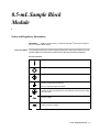
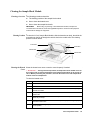
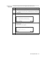
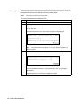
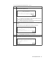
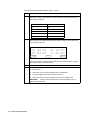
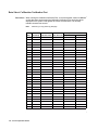
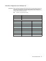
GeneAmp® PCR System 9700
0.5mL Sample Block Module
User’s Manual
© Copyright 2006, 2010 Applied Biosystems. All rights reserved.
Information in this document is subject to change without notice. Applied Biosystems assumes no responsibility for any errors that may appear in this
document.
APPLIED BIOSYSTEMS DISCLAIMS ALL WARRANTIES WITH RESPECT TO THIS DOCUMENT, EXPRESSED OR IMPLIED, INCLUDING
BUT NOT LIMITED TO THOSE OF MERCHANTABILITY OR FITNESS FOR A PARTICULAR PURPOSE. IN NO EVENT SHALL APPLIED
BIOSYSTEMS BE LIABLE, WHETHER IN CONTRACT, TORT, WARRANTY, OR UNDER ANY STATUTE OR ON ANY OTHER BASIS FOR
SPECIAL, INCIDENTAL, INDIRECT, PUNITIVE, MULTIPLE OR CONSEQUENTIAL DAMAGES IN CONNECTION WITH OR ARISING
FROM THIS DOCUMENT, INCLUDING BUT NOT LIMITED TO THE USE THEREOF.
NOTICE TO PURCHASER:LIMITED LICENSE
The combination of the GeneAmp® PCR System 9700 Sample Block Module with a GeneAmp® PCR System 9700 Base Unit is licensed under the
thermal cycler apparatus claims of US patents and patent claims in other countries. No other rights are conveyed expressly, by implication, or by
estoppel. Further information on purchasing licenses may be obtained by contacting the Director of Licensing, Aplied Biosystems, 850 Lincoln Centre
Drive, Foster City, California 94404, USA.
TRADEMARKS:
AB (Design), Applied Biosystems, and MicroAmp are registered trademarks, and Celera Genomics is a trademark of Applied Biosystems or its
subsidiaries in the U.S. and/or certain other countries.
GeneAmp is a registered trademark of Roche Molecular Systems, Inc.
All other trademarks are the sole property of their respective owners.
Part Number 4307808 Rev. D
09/2010
Contents
1 0.5-mL Sample Block Module
Safety and Regulatory Information . . . . . . . . . . . . . . . . . . . . . . . . . . . . . . . . . . . . . . . . . . . . . . 1-1
General Symbols . . . . . . . . . . . . . . . . . . . . . . . . . . . . . . . . . . . . . . . . . . . . . . . . . . . . . . . 1-1
Electrical Safety Testing . . . . . . . . . . . . . . . . . . . . . . . . . . . . . . . . . . . . . . . . . . . . . . . . . 1-2
Instrument Labels . . . . . . . . . . . . . . . . . . . . . . . . . . . . . . . . . . . . . . . . . . . . . . . . . . . . . . 1-2
Operating Precautions . . . . . . . . . . . . . . . . . . . . . . . . . . . . . . . . . . . . . . . . . . . . . . . . . . . . . . . . 1-3
Precautions. . . . . . . . . . . . . . . . . . . . . . . . . . . . . . . . . . . . . . . . . . . . . . . . . . . . . . . . . . . . 1-3
Grounding and Electrical Safety . . . . . . . . . . . . . . . . . . . . . . . . . . . . . . . . . . . . . . . . . . . 1-4
Voltage Quality . . . . . . . . . . . . . . . . . . . . . . . . . . . . . . . . . . . . . . . . . . . . . . . . . . . . . . . . 1-4
Input/Output Connections . . . . . . . . . . . . . . . . . . . . . . . . . . . . . . . . . . . . . . . . . . . . . . . . 1-4
Physical Specifications . . . . . . . . . . . . . . . . . . . . . . . . . . . . . . . . . . . . . . . . . . . . . . . . . . 1-4
Pollution Category . . . . . . . . . . . . . . . . . . . . . . . . . . . . . . . . . . . . . . . . . . . . . . . . . . . . . . 1-5
Instrument Storage. . . . . . . . . . . . . . . . . . . . . . . . . . . . . . . . . . . . . . . . . . . . . . . . . . . . . . 1-5
Communautes Europeennes (CE) Compliance . . . . . . . . . . . . . . . . . . . . . . . . . . . . . . . . 1-5
FCC Compliance (U.S.). . . . . . . . . . . . . . . . . . . . . . . . . . . . . . . . . . . . . . . . . . . . . . . . . . 1-5
Routine Maintenance for Safe Operation . . . . . . . . . . . . . . . . . . . . . . . . . . . . . . . . . . . . 1-5
Technical Support . . . . . . . . . . . . . . . . . . . . . . . . . . . . . . . . . . . . . . . . . . . . . . . . . . . . . . . . . . . . 1-6
To Reach Us On the Web. . . . . . . . . . . . . . . . . . . . . . . . . . . . . . . . . . . . . . . . . . . . . . . . . 1-6
Hours for Telephone Technical Support . . . . . . . . . . . . . . . . . . . . . . . . . . . . . . . . . . . . . 1-6
To Reach Us by Telephone or Fax in North America . . . . . . . . . . . . . . . . . . . . . . . . . . . 1-6
Documents-on-Demand. . . . . . . . . . . . . . . . . . . . . . . . . . . . . . . . . . . . . . . . . . . . . . . . . . 1-7
To Reach Us by E-Mail . . . . . . . . . . . . . . . . . . . . . . . . . . . . . . . . . . . . . . . . . . . . . . . . . . 1-8
Regional Offices Sales and Service . . . . . . . . . . . . . . . . . . . . . . . . . . . . . . . . . . . . . . . . . 1-8
About the 0.5-mL Sample Block Module . . . . . . . . . . . . . . . . . . . . . . . . . . . . . . . . . . . . . . . . 1-11
Overview . . . . . . . . . . . . . . . . . . . . . . . . . . . . . . . . . . . . . . . . . . . . . . . . . . . . . . . . . . . . 1-11
Diagram . . . . . . . . . . . . . . . . . . . . . . . . . . . . . . . . . . . . . . . . . . . . . . . . . . . . . . . . . . . . . 1-11
Sample Block. . . . . . . . . . . . . . . . . . . . . . . . . . . . . . . . . . . . . . . . . . . . . . . . . . . . . . . . . 1-12
Heated Cover . . . . . . . . . . . . . . . . . . . . . . . . . . . . . . . . . . . . . . . . . . . . . . . . . . . . . . . . . 1-13
Peltier Heating/ Cooling Unit . . . . . . . . . . . . . . . . . . . . . . . . . . . . . . . . . . . . . . . . . . . . 1-13
Modules, Accessories, and Disposables . . . . . . . . . . . . . . . . . . . . . . . . . . . . . . . . . . . . . . . . . . 1-14
Overview . . . . . . . . . . . . . . . . . . . . . . . . . . . . . . . . . . . . . . . . . . . . . . . . . . . . . . . . . . . . 1-14
Ordering. . . . . . . . . . . . . . . . . . . . . . . . . . . . . . . . . . . . . . . . . . . . . . . . . . . . . . . . . . . . . 1-14
Installing the 0.5-mL Sample Block Module . . . . . . . . . . . . . . . . . . . . . . . . . . . . . . . . . . . . . . 1-15
Overview . . . . . . . . . . . . . . . . . . . . . . . . . . . . . . . . . . . . . . . . . . . . . . . . . . . . . . . . . . . . 1-15
Installing the Sample Block Module . . . . . . . . . . . . . . . . . . . . . . . . . . . . . . . . . . . . . . . 1-16
Loading Samples . . . . . . . . . . . . . . . . . . . . . . . . . . . . . . . . . . . . . . . . . . . . . . . . . . . . . . . . . . . 1-17
Loading Samples: Overview . . . . . . . . . . . . . . . . . . . . . . . . . . . . . . . . . . . . . . . . . . . . . 1-17
Reaction Tube/Frame Configuration . . . . . . . . . . . . . . . . . . . . . . . . . . . . . . . . . . . . . . . 1-17
i
Loading Samples into the Reaction Tubes . . . . . . . . . . . . . . . . . . . . . . . . . . . . . . . . . .
Placing the Reaction Tubes into the Sample Block . . . . . . . . . . . . . . . . . . . . . . . . . . .
Cleaning the Sample Block Module . . . . . . . . . . . . . . . . . . . . . . . . . . . . . . . . . . . . . . . . . . . .
Cleaning: Overview . . . . . . . . . . . . . . . . . . . . . . . . . . . . . . . . . . . . . . . . . . . . . . . . . . .
Cleaning Position . . . . . . . . . . . . . . . . . . . . . . . . . . . . . . . . . . . . . . . . . . . . . . . . . . . . .
Cleaning the Heated Cover . . . . . . . . . . . . . . . . . . . . . . . . . . . . . . . . . . . . . . . . . . . . . .
Cleaning the Sample Block Wells. . . . . . . . . . . . . . . . . . . . . . . . . . . . . . . . . . . . . . . . .
Running the Calibration Verification Test . . . . . . . . . . . . . . . . . . . . . . . . . . . . . . . . . . . . . . . .
Overview. . . . . . . . . . . . . . . . . . . . . . . . . . . . . . . . . . . . . . . . . . . . . . . . . . . . . . . . . . . .
Equipment Required . . . . . . . . . . . . . . . . . . . . . . . . . . . . . . . . . . . . . . . . . . . . . . . . . . .
Setting Up the 0.5-mL Probe Assembly . . . . . . . . . . . . . . . . . . . . . . . . . . . . . . . . . . . .
Configuring the System 9700 . . . . . . . . . . . . . . . . . . . . . . . . . . . . . . . . . . . . . . . . . . . .
Running the Test . . . . . . . . . . . . . . . . . . . . . . . . . . . . . . . . . . . . . . . . . . . . . . . . . . . . . .
Evaluating the Results. . . . . . . . . . . . . . . . . . . . . . . . . . . . . . . . . . . . . . . . . . . . . . . . . .
1-17
1-18
1-19
1-19
1-19
1-19
1-20
1-21
1-21
1-21
1-22
1-23
1-24
1-26
Running the Temperature Non-Uniformity Test . . . . . . . . . . . . . . . . . . . . . . . . . . . . . . . . . . .
Overview. . . . . . . . . . . . . . . . . . . . . . . . . . . . . . . . . . . . . . . . . . . . . . . . . . . . . . . . . . . .
Equipment Required . . . . . . . . . . . . . . . . . . . . . . . . . . . . . . . . . . . . . . . . . . . . . . . . . . .
Setting Up the 0.5-mL Probe Assembly . . . . . . . . . . . . . . . . . . . . . . . . . . . . . . . . . . . .
Configuring the System 9700 . . . . . . . . . . . . . . . . . . . . . . . . . . . . . . . . . . . . . . . . . . . .
Running the Test . . . . . . . . . . . . . . . . . . . . . . . . . . . . . . . . . . . . . . . . . . . . . . . . . . . . . .
Evaluating the Results. . . . . . . . . . . . . . . . . . . . . . . . . . . . . . . . . . . . . . . . . . . . . . . . . .
Running System Performance Diagnostics . . . . . . . . . . . . . . . . . . . . . . . . . . . . . . . . . . . . . . .
Overview. . . . . . . . . . . . . . . . . . . . . . . . . . . . . . . . . . . . . . . . . . . . . . . . . . . . . . . . . . . .
Equipment Required . . . . . . . . . . . . . . . . . . . . . . . . . . . . . . . . . . . . . . . . . . . . . . . . . . .
Running the Rate Test . . . . . . . . . . . . . . . . . . . . . . . . . . . . . . . . . . . . . . . . . . . . . . . . . .
Running the Cycle Test . . . . . . . . . . . . . . . . . . . . . . . . . . . . . . . . . . . . . . . . . . . . . . . . .
Data Sheet: Calibration Verification Test. . . . . . . . . . . . . . . . . . . . . . . . . . . . . . . . . . . . . . . . .
Instructions . . . . . . . . . . . . . . . . . . . . . . . . . . . . . . . . . . . . . . . . . . . . . . . . . . . . . . . . . .
Data Sheet: Temperature Non-Uniformity Test . . . . . . . . . . . . . . . . . . . . . . . . . . . . . . . . . . . .
Instructions . . . . . . . . . . . . . . . . . . . . . . . . . . . . . . . . . . . . . . . . . . . . . . . . . . . . . . . . . .
1-27
1-27
1-27
1-28
1-29
1-30
1-33
1-34
1-34
1-34
1-34
1-36
1-38
1-38
1-39
1-39
Index
ii
0.5-mL Sample Block
Module
1
Safety and Regulatory Information
IMPORTANT
Read this section before you install the GeneAmp® PCR System 9700 and
the 0.5-mL Sample Block Module.
General Symbols The following symbols are used on Applied Biosystems instruments. Whenever such
symbols appear on instruments, please observe appropriate safety procedures.
Electrical Symbols
This symbol indicates the on position of the main power switch.
This symbol indicates the off position of the main power switch.
This symbol indicates the on/off position of a push-push main power switch.
This symbol indicates that a terminal may be connected to another
instrument’s signal ground reference.
This is not a protected ground terminal.
This symbol indicates that this is a protected ground terminal that must be
connected to earth ground before any other electrical connections are made
to the instrument.
~
~
This symbol indicates that this terminal either receives or delivers alternating
current or voltage.
This symbol indicates that this terminal either receives or delivers alternating
and direct current or voltage.
0.5-mL Sample Block Module 1-1
This symbol indicates the presence of high voltage and warns the user to
proceed with caution.
This symbol alerts you to consult the manual for further information and to
proceed with caution.
Non-electrical Symbols
This symbol illustrates a heater hazard. Proceed with caution when working
around these areas to avoid being burned by hot components.
Electrical Safety Routine safety testing of analytical instruments (e.g., high potential voltage testing)
Testing may be required by various safety agencies.
Testing should only be carried out by qualified personnel after seeking
advice from the Applied Biosystems Service Department.
Instrument Labels The following instrument labels are on the system 9700 with the 0.5-mL Sample Block
Module installed.
! WARNING ! Disconnect supply cord before opening. Grounding
circuit continuity is vital for safe operation of equipment. Never operate
equipment with grounding conductor disconnected.
AVERTISSEMENT: Debrancher le cordon d’alimentation avant d’ouvrir la
continuite des masses est essentielle.
Pour un fonctionnement sans danger. Ne jamais utiliser l’equipment si le fil
de terre n’est pas raccorde.
\
! WARNING ! Hot Surface. Use care when working around this
area to avoid being burned by hot components.
Attention. Surface chaude.
1-2 0.5-mL Sample Block Module
Operating Precautions
Precautions The following precautions should be taken whenever you operate the system 9700
with the 0.5-mL Sample Block Module installed.
Note
This instrument is able to withstand transient overvoltage according to Installation
Category II as defined in IEC 1010-1.
General Use
\
CAUTION The instrument should be used according to the
instructions provided in this manual. If used otherwise, the protection
provided by this instrument may be impaired.
Environment, Humidity, and Temperature
CAUTION
This instrument is designed for indoor use.
CAUTION
Do not operate in a Cold Room or a refrigerated area.
The system 9700 will operate safely when the ambient temperature is
5–40 °C (41–104 °F). The system 9700 will meet performance
specifications when the ambient temperature is 15–30 °C and the
ambient relative humidity is 20–80%. These specifications have been
calculated for altitudes between 0 and 2,000 meters.
CAUTION This instrument is not designed for operation in an
explosive environment. Do not place the instrument close to
potentially explosive materials or objects.
CAUTION This instrument is not designed for operation with the
heated cover retracted when running at 4 °C. If the heated cover is
retracted and the instrument runs at 4 °C, water condensation may
be excessive in the sample block area.
0.5-mL Sample Block Module 1-3
Sample Block Module
! WARNING ! To protect yourself against burns, do not open the
heated cover or touch the sample block module when the word Hot
displays on the screen. This indicates a sample block temperature
above 50 °C.
The hot areas for the 0.5-mL Sample Block Module are shown below.
\
CAUTION To protect your samples and to guarantee the best
temperature uniformity, keep the heated cover closed at all times,
except when loading or unloading samples.
Grounding and The system 9700 must be grounded for protection against electrical shock.
Electrical Safety
! WARNING ! Do not use an adapter to a two-terminal outlet since
this does not provide positive ground protection.
Refer to the GeneAmp® PCR System 9700 Base Module User’s Manual
(P/N 0993-6247) for more information on electrical safety.
Voltage Quality Line voltage must be within ±10% of the nominal value. High or low voltages may have
adverse effects on the electronic components of the instrument. In areas where the
supplied power is subject to fluctuations exceeding these limits, a power line regulator
may be required.
Input/Output Refer to the GeneAmp® PCR System 9700 Base Module User’s Manual
Connections (P/N 0993-6247) for information on the input and output connections of this
instrument.
Physical Refer to the GeneAmp® PCR System 9700 Base Module User’s Manual
Specifications (P/N 0993-6247) for information on the physical specifications of this instrument.
1-4 0.5-mL Sample Block Module
Pollution Category The system 9700 will operate safely in environments that contain nonconductive
foreign matter up to Pollution Degree 2 in IEC 1010-1.
Instrument Storage The system 9700 must be stored at a temperature between -20 °C and 60 °C
(-4 °F and 140 °F) at altitudes ranging from 0–12,000 meters above sea level.
IMPORTANT
The system 9700 is guaranteed to meet performance specifications only
when the ambient temperature is 15–30 °C and the ambient relative humidity is 20–80%
(between altitudes of 0 and 2,000 meters).
Communautes
Europeennes (CE)
Compliance
\
All instruments shipped to the European Union (EU; formerly known as the
European Community) have the CE label on the back of the instrument. This
label signifies that these instruments comply with the Electromagnetic
Compatibility and Low Voltage Directives.
FCC Compliance This product is classified as a digital device used exclusively as industrial,
(U.S.) commercial, or medical test equipment. It is exempt from the technical standards
specified in Part 15 of the FCC Rules and Regulations, based on Section 15.103(c).
Routine Before using any cleaning or decontamination method, except those recommended in
Maintenance for the manual, the user should check with Applied Biosystems to ensure that the
Safe Operation proposed method will not damage the equipment.
Maintain your instrument in good working order. In the event that the instrument has
been subjected to adverse environmental conditions (such as fire, flood, earthquake,
etc.), a service inspection of the instrument should be made to ensure safe operation.
0.5-mL Sample Block Module 1-5
Technical Support
To Reach Us on the Applied Biosystems web site address is:
Web
http://www.appliedbiosystems.com/techsupport
We strongly encourage you to visit our web site for answers to frequently asked
questions, and to learn more about our products. You can also order technical
documents and/or an index of available documents and have them faxed or e-mailed
to you through our site (see the “Documents on Demand” section below).
Hours for Telephone In the United States and Canada, technical support is available at the following times.
Hours
Technical Support Product
Chemiluminescence
9:00 a.m. to 5:00 p.m. Eastern Time
LC/MS
9:00 a.m. to 5:00 p.m. Pacific Time
All Other Products
5:30 a.m. to 5:00 p.m. Pacific Time
See the “Regional Offices Sales and Service” section below for how to contact local
service representatives outside of the United States and Canada.
To Reach Us by Call Technical Support at 1-800-831-6844, and select the appropriate option (below)
Telephone or Fax in for support on the product of your choice at any time during the call. (To open a
North America service call for other support needs, or in case of an emergency, press 1 after dialing
1-800-831-6844.)
For Support On This Product
ABI
PRISM ®
3700 DNA Analyzer
ABI PRISM ® 3100 Genetic Analyzer
BioInformatics (includes BioLIMS™,
BioMerge™, and SQL GT™ applications)
DNA Synthesis
Fluorescent DNA Sequencing
Fluorescent Fragment Analysis (includes
GeneScan ® applications)
Integrated Thermal Cyclers
1-6 0.5-mL Sample Block Module
Dial 1-800-831-6844, and...
Press
FAX
8
650-638-5891
Press
FAX
26
650-638-5891
Press
FAX
25
505-982-7690
Press
FAX
21
650-638-5981
Press
FAX
22
650-638-5891
Press
FAX
23
650-638-5891
Press
FAX
24
650-638-5891
For Support On This Product
PCR and Sequence Detection
Dial 1-800-831-6844, and...
Press
FAX
5, or call
240-453-4613
1-800-762-4001,
and press 1 for
PCR, or 2 for
Sequence
Detection
FMAT
Peptide and Organic Synthesis
Protein Sequencing
Chemiluminescence
LC/MS
Telephone
FAX
1-800-899-5858,
and press 1, then
press 6
508-383-7855
Press
FAX
31
650-638-5981
Press
FAX
32
650-638-5981
Telephone
FAX
1-800-542-2369
(U.S. only), or
781-275-8581
(Tropix)
1-781-271-0045
(Tropix)
9:00 a.m. to
5:00 p.m. ET
Telephone
FAX
1-800-952-4716
650-638-6223
9:00 a.m. to
5:00 p.m. PT
Documents on Free 24-hour access to Applied Biosystems technical documents, including MSDSs, is
Demand available by fax or e-mail.
You can access Documents on Demand through the internet or by telephone:
If you want to
order...
through the
internet
Then...
Use http://www.appliedbiosystems.com/techsupport
You can search for documents to order using keywords.
Up to five documents can be faxed or e-mailed to you by title.
by phone from the
United States or
Canada
a. Call 1-800-487-6809 from a touch-tone phone. Have your fax
number ready.
b. Press 1 to order an index of available documents and have it faxed
to you. Each document in the index has an ID number. (Use this as
your order number in step “d” below.)
c. Call 1-800-487-6809 from a touch-tone phone a second time.
d. Press 2 to order up to five documents and have them faxed to you.
0.5-mL Sample Block Module 1-7
If you want to
order...
by phone from
outside the United
States and
Canada
Then...
a. Dial your international access code, then 1-858-712-0317 from a
touch-tone phone.
Have your complete fax number and country code ready (011
precedes the country code).
b. Press 1 to order an index of available documents and have it faxed
to you. Each document in the index has an ID number. (Use this as
your order number in step “d” below.)
c. Call 1-858-712-0317 from a touch-tone phone a second time.
d. Press 2 to order up to five documents and have them faxed to you.
To Reach Us by Contact technical support by e-mail for help in the following product areas.
Use this e-mail address
E-Mail For this product area
Chemiluminescence
[email protected]
Genetic Analysis
[email protected]
LC/MS
[email protected]
PCR and Sequence Detection
[email protected]
Protein Sequencing, Peptide and DNA
Synthesis
[email protected]
Regional Offices If you are outside the United States and Canada, you should contact your local
Sales and Service Applied Biosystems service representative.
The Americas
United States
Applied Biosystems
850 Lincoln Centre Drive
Foster City, California 94404
Tel:
Fax:
Latin America (Del.A. Obregon, Mexico)
Tel:
Fax:
(305) 670-4350
(305) 670-4349
(650) 570-6667
(800) 345-5224
(650) 572-2743
Europe
Austria (Wien)
Hungary (Budapest)
Tel:
43 (0)1 867 35 75 0
Fax:
43 (0)1 867 35 75 11
Tel:
Fax:
Belgium
Tel:
Fax:
36 (0)1 270 8398
36 (0)1 270 8288
Italy (Milano)
32 (0)2 712 5555
32 (0)2 712 5516
Tel:
Fax:
39 (0)39 83891
39 (0)39 838 9492
Czech Republic and Slovakia (Praha)
The Netherlands (Nieuwerkerk a/d IJssel)
Tel:
Fax:
Tel:
Fax:
420 2 61 222 164
420 2 61 222 168
31 (0)180 331400
31 (0)180 331409
Denmark (Naerum)
Norway (Oslo)
Tel:
Fax:
Tel:
Fax:
1-8 0.5-mL Sample Block Module
45 45 58 60 00
45 45 58 60 01
47 23 12 06 05
47 23 12 05 75
Europe
Finland (Espoo)
Tel:
Fax:
358 (0)9 251 24 250
358 (0)9 251 24 243
Poland, Lithuania, Latvia, and Estonia
(Warszawa)
Tel:
Fax:
48 (22) 866 40 10
48 (22) 866 40 20
France (Paris)
Portugal (Lisboa)
Tel:
Fax:
Tel:
Fax:
33 (0)1 69 59 85 85
33 (0)1 69 59 85 00
351 (0)22 605 33 14
351 (0)22 605 33 15
Germany (Weiterstadt)
Russia (Moskva)
Tel:
Fax:
Tel:
Fax:
49 (0) 6150 101 0
49 (0) 6150 101 101
7 095 935 8888
7 095 564 8787
Spain (Tres Cantos)
South Africa (Johannesburg)
Tel:
Fax:
Tel:
Fax:
34 (0)91 806 1210
34 (0)91 806 1206
27 11 478 0411
27 11 478 0349
Sweden (Stockholm)
United Kingdom (Warrington, Cheshire)
Tel:
Fax:
Tel:
Fax:
46 (0)8 619 4400
46 (0)8 619 4401
44 (0)1925 825650
44 (0)1925 282502
Switzerland (Rotkreuz)
South East Europe (Zagreb, Croatia)
Tel:
Fax:
Tel:
Fax:
41 (0)41 799 7777
41 (0)41 790 0676
385 1 34 91 927
385 1 34 91 840
Middle Eastern Countries and North Africa
(Monza, Italia)
Africa (English Speaking) and West Asia
(Fairlands, South Africa)
Tel:
Fax:
Tel:
Fax:
39 (0)39 8389 481
39 (0)39 8389 493
27 11 478 0411
27 11 478 0349
All Other Countries Not Listed
(Warrington, UK)
Tel:
Fax:
44 (0)1925 282481
44 (0)1925 282509
Japan
Japan (Hatchobori, Chuo-Ku, Tokyo)
Tel:
81 3 5566 6100
Fax:
81 3 5566 6501
Eastern Asia, China, Oceania
Australia (Scoresby, Victoria)
Malaysia (Petaling Jaya)
Tel:
Fax:
Tel:
Fax:
61 3 9730 8600
61 3 9730 8799
60 3 758 8268
60 3 754 9043
China (Beijing)
Singapore
Tel:
Fax:
Tel:
Fax:
86 10 6238 1156
86 10 6238 1162
65 896 2168
65 896 2147
0.5-mL Sample Block Module 1-9
Eastern Asia, China, Oceania
Hong Kong
Taiwan (Taipei Hsien)
Tel:
Fax:
Tel:
Fax:
852 2756 6928
852 2756 6968
886 2 2698 3505
886 2 2698 3405
Korea (Seoul)
Thailand (Bangkok)
Tel:
Fax:
Tel:
Fax:
1-10 0.5-mL Sample Block Module
82 2 593 6470/6471
82 2 593 6472
66 2 719 6405
66 2 319 9788
About the 0.5-mL Sample Block Module
Overview The GeneAmp® PCR System 9700 amplifies nucleic acids using the polymerase
chain reaction (PCR) process. The 0.5-mL Sample Block Module attaches to the top
of the GeneAmp® PCR System 9700 Base Module and allows you to perform up to 60
reactions.
You can remove the 0.5-mL Sample Block Module and replace it with another sample
block module as needed. Interchangeability lets you change sample well formats as
well as throughput capacity.
IMPORTANT
Interchanging sample block modules may require a firmware change. If the
sample block module is placed on a base module running an earlier software version, the
instrument will not operate correctly. To upgrade the base module software, use the 3.5” floppy
disk that is shipped with the 0.5-mL Sample Block Module. For instructions on upgrading the
software, see the GeneAmp® PCR System 9700 Base Module User’s Manual (P/N 0993-6247)
or visit our web site (www.appliedbiosystems.com/techsupport).
Diagram
0.5-mL Sample
Block Module
System 9700
Base Module
Heated cover
Sample block
0.5-mL Sample Block Module 1-11
Sample Block The sample block has 60 wells (10 x 6) for use with GeneAmp® Thin-Walled Tubes
with Flat Caps (0.5-mL volume).
The sample block can operate in one of two modes:
♦
Sample control (0.5-mL Mode button)
In this mode, the instrument calculates the temperature of the sample during
cycling. You can enter various reaction volumes and the instrument will
compensate for this (e.g., 20 µL heats and cools faster than 100 µL). In this mode,
the sample block itself overshoots the setpoint temperature to get the sample to
temperature more quickly, but the sample temperature will not overshoot. The
clock starts counting down hold time once the sample is within one degree of the
setpoint temperature.
Note
The temperature displayed on the screen is the calculated sample temperature.
The illustration below depicts the profile of the sample control mode.
♦
Block control (Block Mode button)
In this mode, the reaction volume and sample temperature are ignored. The
sample block itself goes to the programmed setpoint without overshooting. The
clock starts counting down hold time once the sample block reaches the setpoint
temperature.
Note
1-12 0.5-mL Sample Block Module
The temperature displayed on the screen is the block temperature.
Heated Cover The heated cover slides over the sample block and performs two functions:
♦
It raises the temperature of the upper part of the tube (the part above the sample
block) above the temperature of the sample mixture. This eliminates
condensation, which may have a negative effect on your chemistry.
♦
It puts pressure on the reaction tubes and frame to seat them firmly and precisely
in the sample block. This is important for proper heat transfer.
Peltier Heating/ The internal Peltier heating/cooling unit is housed in the sample block module. The
Cooling Unit sample block module is made of aluminum to provide the optimal thermal transfer
rate.
A Resistive Temperature Device (RTD) sensor in the sample block module provides:
♦
Wide temperature range: 4–99.9 °C
♦
Accuracy: ±0.25 °C from 35–100 °C
♦
Heat/cool rate: 1.5 °C per second
♦
Temperature uniformity: ±0.5 °C (measured 30 seconds after the clock starts)
♦
Long-term stability and high reliability
0.5-mL Sample Block Module 1-13
Modules, Accessories, and Disposables
Overview The modules and accessories listed below are available for the GeneAmp® PCR
System 9700 Base Module. The disposables are for use with the 0.5-mL Sample
Block Module.
Ordering Order modules, accessories, and disposables from Applied Biosystems by part
number. See the tables below.
Modules and Accessories
Part Number
96-Well Sample Block Module
N805-0251
Dual 384-Well Sample Block Module
N805-0400
0.5-mL Sample Block Module
4309131
0.5-mL Sample Block Module Temperature Verification Kit
4309924
Disposables
GeneAmp® 0.5-mL Thermal Insulation Frame (box of 8)
GeneAmp® Thin-Walled Tubes with Flat Caps
Part Number
4308927
N801-0737
1-14 0.5-mL Sample Block Module
Installing the 0.5-mL Sample Block Module
Overview A lever behind the sample block module releases it from the GeneAmp® PCR System
9700 Base Module. Diagrams of the top and bottom of the 0.5-mL Sample Block
Module are shown below.
Lever
Top view, 0.5-mL Sample Block Module
Lever
Bottom view, 0.5-mL Sample Block Module
0.5-mL Sample Block Module 1-15
Installing the To install the sample block module into the GeneAmp® PCR System 9700 Base
Sample Block Module:
Module
Step
Action
1
Pull the lever out from the sample block module.
2
Place the sample block module onto the base module, then push the sample
block module back to seat the electrical connections.
3
Push the lever into the base module to secure the sample block module.
Note
1-16 0.5-mL Sample Block Module
If the sample block module is not seated correctly, the instrument cannot be turned on.
Loading Samples
Loading Samples: The following procedures describe:
Overview ♦ The reaction tube/frame configuration
♦
How to load samples into the reaction tubes
♦
How to place the reaction tubes and frame into the sample block
Reaction Use the following reaction tube/frame configuration for the 0.5-mL Sample Block
Tube/Frame Module.
Configuration
With this
vessel...
Use...
GeneAmp®
GeneAmp®
Thin-Walled Tubes
with Flat Caps
0.5-mL
Thermal
Insulation
Frame
As Shown
GeneAmp
Thin-Walled Tubes
with Flat Caps
GeneAmp 0.5-mL
Thermal Insulation
Frame
Sample block
Loading Samples To load samples into the reaction tubes:
into the Reaction
Step
Action
Tubes
1
Pipette samples into the reaction tubes.
Note
The sample volume range is 20–100 µL.
2
Close the reaction tubes with the flat caps.
3
Continue with “Placing the Reaction Tubes into the Sample Block” on page 1-18.
0.5-mL Sample Block Module 1-17
Placing the Reaction To place the reaction tubes into the sample block:
Tubes into the
Step
Action
Sample Block
1
Place the GeneAmp Thin-Walled Tubes with Flat Caps directly into the sample
block. Set the GeneAmp 0.5-mL Thermal Insulation Frame over the tubes. See the
diagram below.
IMPORTANT Be sure to use the frame. It insulates your samples and prevents the
heated cover from damaging the reaction tubes.
2
Slide the heated cover forward.
Note
To ensure a proper seal, pull the heated cover completely forward.
3
Pull the heated cover lever down to engage the heated cover with the reaction
tubes.
4
Process your samples as usual.
1-18 0.5-mL Sample Block Module
Cleaning the Sample Block Module
Cleaning: Overview The following procedures describe:
♦
The cleaning position of the sample block module
♦
How to clean the heated cover
♦
How to clean the sample block wells
IMPORTANT
Before using any cleaning or decontamination method, except those
recommended in this manual, check with Applied Biosystems to ensure that the proposed
method will not damage the equipment.
Cleaning Position To clean the 0.5-mL Sample Block Module, slide the heated cover back, then slide the
protrusions on the lid up through the vertical slots in the module rails. The cleaning
position is shown below.
Protrusion
Protrusion
Vertical slot
Vertical slot
Cleaning the Heated Clean the heated cover once a month or more frequently if needed.
Cover ! WARNING ! During instrument operation, the temperature of the heated cover can
be as high as 108 °C and the temperature of the sample block module can be as high as
100 °C. Before performing this procedure, wait until the heated cover and sample block
module reach room temperature.
To clean the heated cover:
Step
Action
1
Turn off the instrument.
2
Wait 20–30 minutes for the heated cover to cool down.
3
Raise the heated cover lever and slide the cover back almost, but not completely, to
the back of its slide.
4
Line up the protrusions on the side of the heated cover with the vertical slots in the
module rails.
5
Lift up the front of the heated cover until the protrusions travel up the vertical slots
all the way to the top.
6
Soak a cotton swab or piece of clean cloth with pure isopropanol and gently wipe
the bottom of the cover.
7
Remove any remaining isopropanol from the cover and return the cover to its
normal position.
0.5-mL Sample Block Module 1-19
To clean the heated cover:
Step
8
(continued)
Action
If the cover becomes contaminated with amplified DNA:
a.
Raise the heated cover to the cleaning position.
b.
Wipe the cover with a cloth or cotton swab soaked in 10% bleach.
c.
Wipe with a damp cloth.
Cleaning the Sample Clean the sample block wells once a month or more frequently if needed.
Block Wells
To clean the sample block wells:
Step
Action
1
Turn off the instrument.
2
Wait 1 minute for the sample block module to cool.
3
Remove the reaction tubes and frame from the sample block module and set them
aside.
4
Use a cotton swab soaked in pure isopropanol to clean the sample block wells
thoroughly.
5
Remove any remaining isopropanol from the heated cover before reloading the
reaction tubes and frame.
6
If the sample block wells become contaminated with amplified DNA:
1-20 0.5-mL Sample Block Module
a.
Clean the wells thoroughly with a cotton swab soaked in 10% bleach.
b.
Wipe with a damp cloth.
Running the Calibration Verification Test
Overview Use this test to verify the temperature calibration of your GeneAmp® PCR System
9700 0.5-mL Sample Block Module.
To complete the Calibration Verification Test, you will perform the following
procedures:
Step
Action
See Page
1
Setting Up the 0.5-mL Probe Assembly
1-22
2
Configuring the System 9700
1-23
3
Running the Test
1-24
4
Evaluating the Results
1-26
Equipment Required This test requires the 0.5-mL Sample Block Module Temperature Verification Kit
(P/N 4309924).
Your kit includes:
♦
Cotton swabs
♦
Light mineral oil
♦
GeneAmp® 0.5-mL Thermal Insulation Frame
♦
0.5-mL Probe Assembly
♦
Digital thermometer with 9V battery installed
0.5-mL Sample Block Module 1-21
Setting Up the
To set up the 0.5-mL Probe Assembly:
0.5-mL Probe
Assembly
Step
Action
1
If the heated cover is in the forward position, lift the lever, then slide the heated
cover back.
2
Place the GeneAmp 0.5-mL Thermal Insulation Frame on the sample block.
3
Use a cotton swab to coat well A6 with mineral oil.
4
Place the 0.5-mL Probe Assembly into well A6.
5
Thread the probe wire through the channel in the 0.5-mL Thermal Insulation Frame
to prevent damage to the probe and lead wires.
6
Make sure the probe is connected to the digital thermometer.
7
Slide the heated cover forward and pull the lever down.
IMPORTANT
Seat the probe properly and close the heated cover carefully. If
the probe wire is crushed when the heated cover is closed, the probe may be
damaged.
8
Turn on the digital thermometer.
Note Refer to the instructions included with your Temperature Verification Kit for a
detailed description on operating the digital thermometer.
9
1-22 0.5-mL Sample Block Module
Continue with “Configuring the System 9700” on page 1-23.
Configuring the To configure the system 9700 for the Calibration Verification Test:
System 9700
1
Complete the procedures in “Setting Up the 0.5-mL Probe Assembly” on page 1-22.
2
Turn on the system 9700. The main menu appears.
3
Press Util. The Utilities screen appears.
Note
To press the menu items, use the corresponding F keys. For example, Util
is F4 on this menu.
4
Press Diag. The Diagnostics screen appears.
5
Press TmpVer. The Temperature Verification screen appears.
Temperature Verification
Temp - Calibration Verification
TNU - Temperature Non-Uniformity
6
Temp
TNU
F1
F2
Exit
F3
F4
F5
Press Temp. This automatically configures the system 9700 for the Calibration
Verification Test.
The Calibration Verification screen appears.
Calibration Verification
Block temp = xx.x°C Cover temp = xxx°C
Place probe in well A6
Press Run
Run
F1
7
Cancel
F2
F3
F4
F5
Continue with “Running the Test” on page 1-24.
0.5-mL Sample Block Module 1-23
Running the Test Use the digital thermometer to take temperature readings of the sample well
connected to the 0.5-mL Probe Assembly. You will take a reading at two different
setpoint temperatures.
Note
If necessary, press Cancel to exit the test.
To run the Calibration Verification Test:
Step
Action
1
Complete the procedures in “Configuring the System 9700” on page 1-23.
2
Press Run. This starts the Calibration Verification Test.
Note
To press the menu items, use the corresponding F keys. For example, Run
is F1 on this menu.
The Calibration Verification screen appears with the setpoint value displayed.
Calibration Verification
Block temp = xx.x°C Cover temp = xxx°C
Setpoint is 85°C
Cover must be within 1°C of 105°C
Cancel
F1
F2
F3
F4
F5
Note
The cover must be within 1 °C of 105 °C. It may take several minutes for
the system 9700 to ramp up.
3
The Calibration Verification screen counts down the time until the setpoint is
reached.
Calibration Verification
Block temp = xx.x°C Cover temp = xxx°C
Stabilizing at setpoint... x:xx
Cancel
F1
F2
F3
F4
F5
When the “Stabilizing at setpoint...” value decrements to zero, read the digital
thermometer.
Note
Refer to the instructions included with your Temperature Verification Kit for
a detailed description on operating the digital thermometer.
1-24 0.5-mL Sample Block Module
To run the Calibration Verification Test:
Step
4
(continued)
Action
Using the numeric keys, type the value displayed on the digital thermometer in the
“Enter actual block temperature” field.
Calibration Verification
Block temp = xx.x°C Cover temp = xxx°C
Enter actual block temperature xx.x
Cancel
F1
F2
F3
F4
F5
Note
The digital thermometer displays a four-digit value; round this off to three
digits before typing it in the Calibration Verification screen.
Note
If desired, record this value on the Calibration Verification Test Data Sheet
(page 1-38) to keep a permanent record of the test.
5
Press ENTER. The system 9700 automatically begins the second reading (45 °C
setpoint).
The Calibration Verification screen appears with the setpoint value displayed.
Calibration Verification
Block temp = xx.x°C Cover temp = xxx°C
Setpoint is 45°C
Cover must be within 1°C of 105°C
Cancel
F1
Note
F2
F3
F4
F5
The cover must be within 1 °C of 105 °C.
6
Repeat steps 3 and 4 for the second reading.
7
The system 9700 evaluates the calibration of the sample block temperature for the
setpoint values you entered and displays the results. A summary screen appears at
the conclusion of the test.
Calibration Verification
Actual temperature at 85 °C
Actual temperature at 45 °C
xx.x
xx.x
Cancel
Accept
F1
F2
F3
F4
F5
If you entered values on the Calibration Verification Test Data Sheet, compare those
values with the actual test results.
8
Press Accept. To interpret the results, see “Evaluating the Results” on page 1-26.
0.5-mL Sample Block Module 1-25
To run the Calibration Verification Test:
Step
9
(continued)
Action
When you have completed all measurements, be sure to:
♦
Press Exit.
♦
Remove the 0.5-mL Probe Assembly from the sample block.
♦
Turn off the digital thermometer and clean off the oil.
♦
Remove the 0.5-mL Thermal Insulation Frame from the sample block.
IMPORTANT
Make sure the sample block is at room temperature (~25 °C)
before removing the frame.
Evaluating the When the system 9700 completes the Calibration Verification Test, one of two screens
Results appears. See the table below to evaluate the results.
If the sample block
module...
Is properly calibrated
Then the...
Calibration Verification screen appears with the following
message displayed.
Calibration Verification
Calibration is good
Exit
F1
Does not pass the
Calibration Verification
Test
F2
F3
F4
F5
Calibration Verification screen appears with the following
message displayed.
Calibration Verification
Instrument may require service.
Contact Applied Biosystems
Technical Support.
Exit
F1
1-26 0.5-mL Sample Block Module
F2
F3
F4
F5
♦
If the test fails, repeat the procedure to make sure the meter
was not misread or that errors were not made entering data.
♦
If the test fails again, contact Applied Biosystems Technical
Support. See “Technical Support” on page 1-6.
Running the Temperature Non-Uniformity Test
Overview Use this test to verify the temperature uniformity of the GeneAmp® PCR System 9700
0.5-mL Sample Block Module.
To complete the Temperature Non-Uniformity Test, you will perform the following
procedures:
Step
Action
See Page
1
Setting Up the 0.5-mL Probe Assembly
1-28
2
Running the Test
1-30
3
Evaluating the Results
1-33
Equipment Required This test requires the 0.5-mL Sample Block Module Temperature Verification Kit
(P/N 4309924).
Your kit includes:
♦
Cotton swabs
♦
Light mineral oil
♦
GeneAmp® 0.5-mL Thermal Insulation Frame
♦
0.5-mL Probe Assembly
♦
Digital thermometer with 9V battery installed
0.5-mL Sample Block Module 1-27
Setting Up the
To set up the 0.5-mL Probe Assembly:
0.5-mL Probe
Assembly
Step
Action
1
If the heated cover is in the forward position, lift the lever, then slide the heated
cover back.
2
Place the GeneAmp 0.5-mL Thermal Insulation Frame on the sample block.
3
Use a cotton swab to coat the following wells with mineral oil:
4
A1
D1
A6
D7
A10
E8
B3
F1
C5
F5
C10
F10
Place the 0.5-mL Probe Assembly into well A1.
Note
As the test progresses, you will move the 0.5-mL Probe Assembly to each
of the test wells.
5
Thread the probe wire through the channel in the 0.5-mL Thermal Insulation Frame
to prevent damage to the probe and lead wires.
6
Make sure the probe is connected to the digital thermometer.
7
Slide the heated cover forward and pull the lever down.
IMPORTANT
Seat the probe properly and close the heated cover carefully. If
the probe wire is crushed when the heated cover is closed, the probe may be
damaged.
8
Turn on the digital thermometer.
Note Refer to the instructions included with your Temperature Verification Kit for a
detailed description on operating the digital thermometer.
9
1-28 0.5-mL Sample Block Module
Continue with “Configuring the System 9700” on page 1-29.
Configuring the To configure the system 9700 for the Temperature Non-Uniformity Test:
System 9700
1
Complete the procedures in “Setting Up the 0.5-mL Probe Assembly” on page 1-28.
2
Turn on the system 9700. The main menu appears.
3
Press Util. The Utilities screen appears.
Note
To press the menu items, use the corresponding F keys. For example, Util
is F4 on this menu.
4
Press Diag. The Diagnostics screen appears.
5
Press TmpVer. The Temperature Verification screen appears.
Temperature Verification
Temp - Calibration Verification
TNU - Temperature Non-Uniformity
6
Temp
TNU
F1
F2
Exit
F3
F4
F5
Press TNU. This automatically configures the system 9700 for the Temperature
Non-Uniformity Test.
The TNU Performance screen appears.
TNU Performance
Sample temp = xx.x°C Cover temp = xxx°C
Place Probe in well A1
Press Run
Run
F1
7
Cancel
F2
F3
F4
F5
Continue with “Running the Test” on page 1-30.
0.5-mL Sample Block Module 1-29
Running the Test The Temperature Non-Uniformity Test uses the 0.5-mL Probe Assembly to test the
temperature uniformity of 12 different wells in the sample block.
Note
If necessary, press Cancel to exit the test.
To run the Temperature Non-Uniformity Test:
Step
Action
1
Complete the procedures in “Setting Up the 0.5-mL Probe Assembly” on page 1-28.
2
Press Run. This starts the Temperature Non-Uniformity Test.
Note
To press the menu items, use the corresponding F keys. For example, Run
is F1 on this menu.
The TNU Performance screen appears with the setpoint value displayed.
TNU Performance
Sample temp = xx.x°C Cover temp = xxx°C
Setpoint is 94°C
Sample must be within 1.0°C of setpoint
Cancel
F1
F2
F3
F4
F5
Note
The sample block must be within 1.0 °C of the setpoint. In addition, the
cover must be within 1 °C of 105 °C. It may take several minutes for the system
9700 to ramp up.
3
The TNU Performance screen counts down the time until the setpoint is stabilized.
TNU Performance
Sample temp = xx.x°C Cover temp = xxx°C
Stabilizing at setpoint... x:xx
Cancel
F1
F2
F3
F4
F5
When the “Stabilizing at setpoint...” value decrements to zero, read the digital
thermometer.
Note
Refer to the instructions included with your Temperature Verification Kit for
a detailed description on operating the digital thermometer.
1-30 0.5-mL Sample Block Module
To run the Temperature Non-Uniformity Test:
Step
4
(continued)
Action
Using the numeric keys, type the value displayed on the digital thermometer in the
“Enter actual block temperature” field.
TNU Performance
Sample temp = xx.x°C Cover temp = xxx°C
Enter actual block temperature 00.0
Cancel
F1
F2
F3
F4
F5
Note
The digital thermometer displays a four-digit value; round this off to three
digits before typing it in the TNU Performance screen.
Note
If desired, record this value on the Temperature Non-Uniformity Test Data
Sheet (page 1-39) to keep a permanent record of the test.
5
Press ENTER. The system 9700 automatically begins the second reading (37 °C
setpoint).
The TNU Performance screen appears with the setpoint value displayed.
TNU Performance
Sample temp = xx.x°C Cover temp = xxx°C
Setpoint is 37°C
Sample must be within 1.0°C of setpoint
Cancel
F1
Note
F2
F3
F4
F5
The sample block must be within 1.0 °C of the setpoint.
6
Repeat steps 3 and 4 for the second reading.
7
Press ENTER. The TNU Performance screen appears with the following prompt:
TNU Performance
Sample temp = xx.x°C Cover temp = xxx°C
Place probe in well xx
Press Run
Run
F1
Cancel
F2
F3
F4
F5
0.5-mL Sample Block Module 1-31
To run the Temperature Non-Uniformity Test:
Step
8
9
(continued)
Action
Slide the heated cover back and repeat steps 4–7 of “Setting Up the 0.5-mL Probe
Assembly” on page 1-28 and steps 2–7 of this procedure. Complete these steps for
all 12 wells to be tested:
A1
D1
A6
D7
A10
E8
B3
F1
C5
F5
C10
F10
The system 9700 evaluates the uniformity of the sample block temperature for the
setpoint values you entered and displays the results. A summary screen appears at
the conclusion of the test.
Well
A1
A6
A10
B3
Accept
F1
94 °C
37 °C
xx.x
xx.x
xx.x
xx.x
xx.x
xx.x
xx.x
xx.x
F2
Well
C5
C10
D1
D7
More
F3
94 °C
37 °C
xx.x
xx.x
xx.x
xx.x
xx.x
xx.x
xx.x
xx.x
Cancel
F4
F5
If you entered values on the Temperature Non-Uniformity Test Data Sheet, compare
those values with the actual test results.
10
Press Accept. To interpret the results, see “Evaluating the Results” on page 1-33.
11
When you have completed all measurements, be sure to:
♦
Press Cancel.
♦
Remove the 0.5-mL Probe Assembly from the sample block.
♦
Turn off the digital thermometer and clean off the oil.
♦
Remove the 0.5-mL Thermal Insulation Frame from the sample block.
IMPORTANT
Make sure the sample block is at room temperature (~25 °C)
before removing the frame.
1-32 0.5-mL Sample Block Module
Evaluating the When the system 9700 completes the Temperature Non-Uniformity Test, the TNU
Results Performance screen appears. See the table below to evaluate the results.
If the...
Then...
Temperature of the
sample block wells is
uniform,
“Pass” appears after each setpoint temperature.
TNU Performance
TNU at 94°C is xx.xx - Pass
TNU at 37°C is xx.xx - Pass
Cancel
F1
Temperature variation of
the sample block wells
exceeds performance
specifications,
F2
F3
F4
F5
“Fail” appears after the setpoint temperature(s) for which the test
failed.
TNU Performance
TNU at 94°C is xx.xx - Fail
TNU at 37°C is xx.xx - Fail
Cancel
F1
F2
F3
F4
F5
♦
If the test fails, repeat the procedure to make sure the meter
was not misread or that errors were not made entering data.
♦
If the test fails again, contact Applied Biosystems Technical
Support. See “Technical Support” on page 1-6.
0.5-mL Sample Block Module 1-33
Running System Performance Diagnostics
Overview After you have configured the GeneAmp® PCR System 9700, conduct the System
Performance Diagnostics to verify the integrity of the cooling and heating system.
There are two System Performance Diagnostics:
♦
Rate Test
♦
Cycle Test
Equipment Required These diagnostics require:
♦
GeneAmp® 0.5-mL Thermal Insulation Frame
Running the Rate Use the Rate Test to verify that the Peltier units are operating correctly. The test takes
Test approximately 10 minutes to run.
To run the Rate Test:
Step
Action
1
Turn on the system 9700. The main menu appears.
2
Press Util. The Utilities screen appears.
Note
To press the menu items, use the corresponding F keys. For example, Util
is F4 on this menu.
3
Press Diag. The Diagnostics screen appears.
4
Press System. The System Performance screen appears.
System Performance
Rate - Cool and Heat Rate Test
Cycle - Cycle Performance Test
5
Rate
Cycle
F1
F2
Exit
F3
F4
F5
Press Rate from the System Performance screen.
WARNING!!!
Install the appropriate empty
Consumables into the Sample Block.
Refer to System Performance Section
of Block User Manual.
Cancel
Cont
F1
Note
F2
F3
F4
F5
You will install the GeneAmp 0.5-mL Thermal Insulation Frame.
6
Place the 0.5-mL Thermal Insulation Frame in the sample block. Slide the heated
cover forward and pull the lever down.
7
After you have installed the frame, press Cont.
The instrument runs through a series of tests where the sample block is stabilized
at 35 °C, 94 °C, and 4 °C.
1-34 0.5-mL Sample Block Module
To run the Rate Test:
Step
8
(continued)
Action
At the conclusion of the test, the Cool and Heat Rate Test screen appears. The
screen displays the test results and whether the test passed or failed.
Cool and Heat Rate Test
Pass
Heating rate: x.xx °C/s
Cooling rate: x.xx °C/s
Cancel
Print
F1
F2
F3
F4
F5
Check your Rate Test results against the passing ranges listed below.
9
Heating Rate
> 1.5 °C /second
Cooling Rate
> 1.5 °C /second
If the test fails, repeat the procedure once.
If the test fails again, contact Applied Biosystems Technical Support. See “Technical
Support” on page 1-6.
0.5-mL Sample Block Module 1-35
Running the Cycle Use the Cycle Test to verify that the PCR cycling function operates properly. This test
Test takes approximately 15 minutes to run.
To run the Cycle Test:
Step
Action
1
Turn on the system 9700. The main menu appears.
2
Press Util. The Utilities screen appears.
Note
To press the menu items, use the corresponding F keys. For example, Util
is F4 on this menu.
3
Press Diag. The Diagnostics screen appears.
4
Press System. The System Performance screen appears.
System Performance
Rate - Cool and Heat Rate Test
Cycle - Cycle Performance Test
5
Rate
Cycle
F1
F2
Exit
F3
F4
F5
Press Cycle from the System Performance screen. This runs the Cycle Test.
WARNING!!!
Install the appropriate empty
Consumables into the Sample Block.
Refer to System Performance Section
of Block User Manual.
Cancel
Cont
F1
Note
F2
F3
F4
F5
You will install the GeneAmp 0.5-mL Thermal Insulation Frame.
6
Place the 0.5-mL Thermal Insulation Frame in the sample block. Slide the heated
cover forward and pull the lever down.
7
After you have installed the frame, press Cont.
The Cycle Test executes a two-temperature PCR cycling protocol, then measures
and reports the average cycle time and the cycle-to-cycle variation.
IMPORTANT Pressing Pause during the Cycle Test may generate false test results. Re-run
the Cycle Test if Pause was pressed during the test.
1-36 0.5-mL Sample Block Module
To run the Cycle Test:
Step
8
(continued)
Action
At the conclusion of the test, the Cycle Performance screen appears. The screen
displays the test results and whether the test passed or failed.
Cycle Performance
Pass
Average Cycle Time: xxx.x sec
x.x sec
Cycle Time STD:
Print
F1
Cancel
F2
F3
F4
F5
Check your Cycle Test results against the passing ranges listed below.
Average Cycle Time £ 125 seconds
Cycle Time STD
9
< 5 seconds
If the test fails, repeat the procedure once.
If the test fails again, contact Applied Biosystems Technical Support. See “Technical
Support” on page 1-6.
0.5-mL Sample Block Module 1-37
Data Sheet: Calibration Verification Test
Instructions When running the Calibration Verification Test, record the setpoint values for well A6
on this data sheet. At the end of the Calibration Verification Test, check the values
displayed on the system 9700 against the values recorded here. This will help
maintain accurate test records.
Note
If desired, you may photocopy this page.
.
Setpoint Value: Well A6
Date
1-38 0.5-mL Sample Block Module
Tested By Probe Serial No. Meter Serial No.
85 °C
45 °C
Data Sheet: Temperature Non-Uniformity Test
Instructions When running the Temperature Non-Uniformity Test, record the setpoint values for the
wells listed on this data sheet. At the end of the Temperature Non-Uniformity Test,
check the values displayed on the system 9700 against the values recorded here. This
will help maintain accurate test records.
Note
If desired, you may photocopy this page.
Date
Tested By
Probe Serial No.
Meter Serial No.
Setpoint Value
94 °C
37 °C
A1
A6
A10
B3
C5
C10
D1
D7
E8
F1
F5
F10
0.5-mL Sample Block Module 1-39
1-40 0.5-mL Sample Block Module
Index
Numerics
0.5-mL Probe Assembly, setting up
Calibration Verification Test 1-21
Temperature Non-Uniformity
Test 1-27
0.5-mL Sample Block Module
cleaning the heated cover 1-18
cleaning the sample block
wells 1-19
diagrams
attached to 9700 Base
Module 1-10
cleaning position 1-18
reaction tube/frame
configuration 1-16
top and bottom views 1-14
heated cover 1-12
installing 1-15
overview 1-10
part number 1-13
Peltier heating/cooling unit 1-12
sample block 1-11
modes 1-11
0.5-mL Sample Block Module
Temperature Verification Kit
part number 1-13
96-Well Sample Block Module
part number 1-13
reaction tube/frame 1-16
cooling
information 1-12
verifying cooling system 1-33
customer support
e-mail address 1-8
help 1-6–1-9
internet address 1-6
regional sales offices 1-8–1-9
telephone/fax (U.S.) 1-6
Cycle Test, running 1-35–1-36
H
heated cover
about 1-12
cleaning 1-18
DNA contamination 1-19
heating and cooling, information 1-12
help
e-mail address 1-8
internet address 1-6
regional sales offices 1-8–1-9
telephone hours 1-6
telephone/fax (U.S.) 1-6
D
data sheets
Calibration Verification Test 1-37
Temperature Non-Uniformity
Test 1-38
diagnostics 1-33–1-36
Cycle Test, running 1-35–1-36
Rate Test, running 1-33–1-34
digital thermometer 1-21, 1-27
Calibration Verification Test 1-20
Temperature Non-Uniformity
Test 1-26
DNA contamination
heated cover 1-19
sample block wells 1-19
Dual 384-Well Sample Block Module
part number 1-13
I
input/output connections 1-4
installing the sample block
module 1-15
instrument labels 1-2
interchangeability
sample block modules 1-10
internet address
FAX-on-Demand 1-7
L
loading samples
1-16–1-17
M
maintenance, routine
1-5
B
block control mode 1-11
burns, warning symbol 1-2
C
Calibration Verification
Test 1-20–1-25
0.5-mL Probe Assembly, setting
up 1-21
data sheet 1-37
evaluating the results 1-25
required equipment 1-20
running the test 1-23–1-25
cleaning
DNA contamination
heated cover 1-19
sample block wells 1-19
heated cover 1-18
position 1-18
sample block wells 1-19
Communautes Europeennes (CE)
Compliance 1-5
configuration
E
electrical safety testing 1-2
electrical symbols 1-1
e-mail, address for technical
support 1-8
F
FAX on Demand 1-7
FCC compliance 1-5
frame
configuration 1-16
part number 1-13
G
GeneAmp® 0.5-mL Thermal Insulation
Frame
part number 1-13
GeneAmp® Thin-Walled Tubes with
Flat Caps
part number 1-13
grounding and electrical safety 1-4
N
non-electrical symbols
1-2
O
operating precautions 1-3–1-5
Communautes Europeennes (CE)
Compliance 1-5
environment, humidity, and
temperature 1-3
FCC compliance 1-5
general use 1-3
grounding and electrical
safety 1-4
input/output connections 1-4
instrument storage 1-5
physical specifications 1-4
pollution categoy 1-5
routine maintenance 1-5
sample block module 1-4
voltage quality 1-4
ordering parts 1-13
Index-1
P
parts
modules, accessories, and
disposables 1-13
ordering 1-13
PCR cycling function,
testing 1-35–1-36
Peltier unit
heating/cooling unit 1-12
verifying running correctly 1-33
performance tests 1-33–1-36
Cycle Test, running 1-35–1-36
Rate Test, running 1-33–1-34
pollution category 1-5
R
Rate Test, running 1-33–1-34
reaction tube
configuration 1-16
loading samples 1-16
S
safety and regulatory
information 1-1–1-2
electrical safety testing 1-2
instrument labels 1-2
sample block
about 1-11
cleaning the wells 1-19
modes 1-11
verifying calibration 1-20–1-25
0.5-mL Probe
Assembly 1-21
evaluating the results 1-25
required equipment 1-20
running the test 1-23–1-25
verifying temperature
uniformity 1-26–1-32
0.5-mL Probe
Assembly 1-27
evaluating the results 1-32
required equipment 1-26
running the test 1-29–1-31
wells
DNA contamination 1-19
sample block modules
interchanging 1-10
sample control mode 1-11
samples
loading 1-16–1-17
loading into reaction tubes 1-16
placing into the sample
block 1-17
specifications, physical 1-4
storing instrument 1-5
symbols
burns, warning 1-2
Index-2
Communautes Europeennes (CE)
Compliance 1-5
electrical 1-1
non-electrical 1-2
System Performance Diagnostics
required equipment 1-33
system performance tests,
running 1-33–1-36
Cycle Test, running 1-35–1-36
Rate Test, running 1-33–1-34
T
technical support 1-6–1-9
e-mail address 1-8
internet address 1-6
regional sales offices 1-8–1-9
telephone/fax (U.S.) 1-6
Temperature Non-Uniformity
Test 1-26–1-32
data sheet 1-38
evaluating the results 1-32
required equipment 1-26
running the test 1-29–1-31
tests
Calibration Verification
Test 1-20–1-25
0.5-mL Probe Assembly,
setting up 1-21
evaluating the results 1-25
required equipment 1-20
running the test 1-23
system performance 1-33–1-36
Cycle Test,
running 1-35–1-36
Rate Test,
running 1-33–1-34
System Performance Diagnostics
required equipment 1-33
Temperature Non-Uniformity
Test 1-26–1-32
0.5-mL Probe Assembly,
setting up 1-27
evaluating the results 1-32
required equipment 1-26
running the test 1-29
TmpVer soft key, using to run
Calibration Verification
Test 1-22
TmpVer soft key, using to run
Temperature Non-Uniformity
Test 1-28
tubes
part number 1-13
V
voltage quality
1-4
W
www address
Applied Biosystems 1-6
FAX-on-Demand 1-7
Worldwide Sales and Support
Applied Biosystems vast distribution and
service network, composed of highly trained
support and applications personnel,
reaches 150 countries on six continents.
For sales office locations and technical support,
please call our local office or refer to our
Web site at www.appliedbiosystems.com.
Applied Biosystems is committed to
providing the world’s leading technology
and information for life scientists.
Headquarters
850 Lincoln Centre Drive
Foster City, CA 94404 USA
Phone: +1 650.638.5800
Toll Free (In North America): +1 800.345.5224
Fax: +1 650.638.5884
09/2010
www.appliedbiosystems.com
Part Number 4307808 Rev. D