1
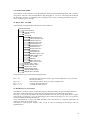
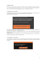
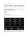
DEFENDER
ABS-TC module
User’s manual
ver 1.1
www.nanocom.it
1
INDEX
1.1 INTRODUCTION................................................................................................................................... 3
1.2 GENERAL INFORMATION.................................................................................................................. 3
2 STANDALONE MODE ............................................................................................................................ 4
2.1 MENU DEF. ALLARM.......................................................................................................................... 4
2.2 READ FAULTS FUNCTION ................................................................................................................. 4
2.3 CLEAR FAULT CODE FUNCTION ..................................................................................................... 5
2.4 INPUTS FUNCTION.............................................................................................................................. 5
2.7 OUTPUTS FUNCTIONS........................................................................................................................ 6
2.8 FRONT LEFT TEST FUNCTION.......................................................................................................... 7
2.9 FRONT RIGHT TEST FUNCTION ....................................................................................................... 7
2.10 REAR LEFT TEST FUNCTION .......................................................................................................... 7
2.11 REAR RIGHT TEST FUNCTION........................................................................................................ 7
2.12 POWER BLEED FUNCTION .............................................................................................................. 7
2.13 MODULATOR BLEED FUNCTION................................................................................................... 8
3 REMOTE MODE....................................................................................................................................... 9
3.1 READ FAULTS FUNCTION ................................................................................................................. 9
3.10 POWER BLEED FUNCTION ............................................................................................................ 13
3.11 MODULATOR BLEED FUNCTION................................................................................................. 13
3.2 CLEAR FAULTS FUNCTION............................................................................................................... 9
3.3 OPEN FAULT FILE FUNCTION ........................................................................................................ 10
3.4 READ INPUTS FUNCTION ................................................................................................................ 10
3.5 OUTPUTS FUNCTIONS...................................................................................................................... 12
3.6 FRONT RIGHT TEST FUNCTION ..................................................................................................... 12
3.7 FRONT LEFT TEST FUNCTION........................................................................................................ 12
3.8 REAR RIGHT TEST FUNCTION........................................................................................................ 12
3.9 REAR LEFT TEST FUNCTION .......................................................................................................... 13
APPENDIX ................................................................................................................................................. 14
TABLE 1: COMPLETE FAULT CODE LIST ........................................................................................... 14
2
1.1 INTRODUCTION
In this manual only the diagnostic functions related to DEFENDER ABS are described and
it’s taken for garanted that the user knows the NANOCOM basic functions concerning
how to explore the menus and how to manage the NANOCOM-generated files. It’s thus
recommended to carefully read the document “NANOCOM user manual.pdf” where
these subjects are dealt with.
1.2 GENERAL INFORMATION
Like the diagnostic functions related to engine TD5’s management, NANOCOM allows to perform
diagnostic functions related to DEFENDER alarm in STANDALONE mode, that is completely
independent from the PC usage by visualizing the interactive functions on the display on the NANOCOM
interface, or in REMOTE mode by employing the application NANOCOM.exe for PC.
As for the STANDALONE mode, once NANOCOM is running it is necessary to press key 3 or key 4 (<<
>>) until the display shows the writing “DEF. ABS” in order to have access to the alarm diagnostic
functions.
At this point, key 1 “ent” allows to have access to the submenu containing the various functions and
described in section 2.1.
In REMOTE mode, instead, you have to press button DEF. ABS in the exploration area which allows to
expand the buttons that start the diagnostic functions described in chapter .
NOTA: To make NANOCOM communicate with ABS ECU, like with the TD5 ECU diagnostic functions,
the ignition has to be on.
3
2 STANDALONE MODE
In this chapter it’s described how to use the diagnostic functions in STANDALONE mode, that is without
using the PC. The user is thus recommended to read paragraphs 4.1.1-4.1.2-4.1.3 describing this mode and
all paragraphs of section 4.3 explaining how to manage th files; section 4.5 dealing with file saving; and
the 4.7 concerning error messages.
2.1 MENU DEF. ALLARM
The following tree diagram shows the structure of this submenu:
DEFENDER ABS
READ EVENT
CLEAR EVENT
INPUTS
OUTPUTS
FRONT RIGHT IN
FRONT RIGHT OUT
FRONT LEFT IN
FRONT LEFT OUT
REAR RIGHT IN
REAR RIGHT OUT
REAR LEFT IN
REAR LEFT OUT
PUMP RELAY
VALVE REALY
BRAKE WARN. LED
ABD WARN. LED
T.C. LAMP
SPEEDO
HDC INFO LED
HDC FAULT LED
FRONT LEFT TEST
FRONT RIGHT TEST
REAR LEFT TEST
REAR RIGHT TEST
ABS POWER BLEED
ABS MODUL. BLEED
In this menu the keys perform the following functions:
Key 1: ent
Key 2: esc
Key 3: “←←”
Key 4: “→→”
ENTER (gets the function started, or gets into the submenu in case you choose
the item “OUTPUT”)
ESCAPE (gets back to the level of the preceding menu).
scrolling the menu backward
scrolling the menu forward
2.2 READ FAULTS FUNCTION
The ABS ECU contains a register which memorizes the faults detected by the system and the number of
times these are detected, making a distinction between intermittent errors faults and current faults.
Once key 1 “ent” has been pressed at the menu item READ FAULTS, the writing “Read faults?” appears
on the display: pressing key 1 “yes” the function gets started, whereas pressing key 4 “not” you get back to
the menu without performing the function.
If the communication is correct, the LED will flash, and if the function is completely performed, the
display will show the list of the events.
The faults are listed with the numeric codes. To get to know the meanings of the numeric code see
appended table 1.
4
At this point the keys have the following functions:
Key 1:
Key 2: esc
Key 3: “bak”
Key 4: “→→”
no function
ESCAPE (gets to the level of the previous menu).
gets to the first code
goes on to the following code
To get to the main menu press “esc” or scroll through all the listed events by using key 4: in both cases,
before getting to the main menu the writing “Save this file?” appears on the display. Pressing key 1 “yes”
you store a file containing the faults triggered by the ECU; whereas pressing key 4 “not” you get back
straight to the menu.
The file generated is stored in NANOCOM’s memory with extention .fa3, it will thus be possibile to
visualize these faults later in text format transferring this file on the PC.
The faults are featured as follows:
AA-B NNN
Where ‘AA-B’ is the number of the fault, and NNN is the number of times the fault has been detected
2.3 CLEAR FAULT CODE FUNCTION
Once the key 1 “ent” has been pressed at the menu item CLEAR FAULT, the writing “Clear faults?” will
appear on the display: pressing key 1 “yes” the function gets started, whereas pressing key 4 “not” you get
back to the menu without performing the function.
If the communication is on, the LED will flash, and if the function is correctly performed, the display will
show the writing “the fault codes have been cleared".
At the end of the function, you don’t need to press any key, NANOCOM gets automatically to the menu.
2.4 INPUTS FUNCTION
Once the key 1 “ent” has been pressed at the menu item INPUTS, the writing “Read inputs?” will appear
on the display: pressing key 1 “yes” the alarm input reading function gets started, where as pressing key 4
“not” you get back to the menu without performing the function.
This function scans continously all the inputs with the frequency of about one second. If the
communication is on, the LED will flash continously for as long as the scan is performed.
At this point the keys perform the following functions:
Key 1:
Key 2: stop
Key 3: “←←”
Key 4: “→→”
no function
stop the scanning.
show previous parameter
show following parameter
The different parameters are shown one by one on the first line of the display.
The parameters of which the scanning is performed are the following:
FLSens(Front Left sensor)
FRSens(Front Right sensor)
RLSens(Rear Left sensor)
RRSens(Rear Right sensor)
Value (volts) of the front left sensor
Value (volts) of the front right sensor
Value (volts) of the rear left sensor
Value (volts) of the rear right sensor
FLOV(Front Left outlet valve)
FROV(Front Left outlet valve)
RLOV(Rear Left outlet valve)
RROV(Rear Right outlet valve)
FLIV(Front Left inlet valve)
FRIV(Front Right inlet valve)
RLIV(Rear Left inlet valve)
RRIV(Rear Right inlet valve)
Driving value of the front right outlet valve
Driving value of the front left outlet valve
Driving value of the rear left outlet valve
Driving value of the rear right outlet valve
Driving value of the front left inlet valve
Driving value of the front right inlet valve
Driving value of the rear left inlet valve
Driving value of the rear right inlet valve
5
FLWS(Front Left Wheel speed)
FRWS(Front Right Wheel speed)
RLWS(Rear Left Wheel speed)
RRWS(Rear Right Wheel speed)
Speed value detected on the front left wheel
Speed value detected on the front right wheel
Speed value detected on the rear left wheel
Speed value detected on the rear right wheel
Eng. speed(Engine speed)
Eng. torque(Engine torque)
Throt. Pos(throttle position)
Brake light
Pump Relay
Ign. Relay(ignition relay)
Valve sup.(Valve supply)
PMV(Pump monitor voltage)
GND ref.(Ground reference)
Shut.sw(Shuttle switch)
Engine speed
Engine torque in percentage
Throttle position
Driving value of the brake light relay
Driving value of the pump relay
Driving value of the ignition relay
Value of the valve supply
Value of the pump monitor voltage
Value (volts) ground reference
Shuttle switch
2.7 OUTPUTS FUNCTIONS
These functions are in a submenu of the menu DEF. ABS, so when the display shows the item OUTPUTS,
pressing key 1 “ent” you get to the submenu containing the following items. Each of these items allows to
activate the test of the corresponding output.
FRONT RIGHT IN
FRONT RIGHT OUT
FRONT LEFT IN
FRONT LEFT OUT
REAR RIGHT IN
REAR RIGHT OUT
REAR LEFT IN
REAR LEFT OUT
PUMP RELAY
VALVE REALY
BRAKE WARN. LED
ABS WARN. LED
T.C. LAMP
SPEEDO
HDC INFO LED
HDC FAULT LED
Activates or deactivates the front right inlet valve
Activates or deactivates the front right outlet valve
Activates or deactivates the front left inlet valve
Activates or deactivates the front left outlet valve
Activates or deactivates the rear right inlet valve
Activates or deactivates the rear right outlet valve
Activates or deactivates the rear left inlet valve
Activates or deactivates the rear left outlet valve
Activates the ABS pump relay
Activates the ABS valve relay
Activates the brake warning led
Activates the ABS warning led
Activates the TD lamp
Activates the output of the tachometer with a reference of 100 mph
Activates the lamp indicating that the HDC system is on
Activates the HDC mil lamp
You’ll perform the function by pressing key 1 “ent”.
Now the keys will acquire the following functions:
Key 1: esc
Key 2:
Key 3: “on”
Key 4: “off”
leaves the function
no function
activates the test
stops the test
Once within the function, you’ll activate the test by pressing key 3 “on”. You keep on performing it until
you press key 4 “off” or you leave the function through key 1 “esc”.
6
2.8 FRONT LEFT TEST FUNCTION
This function allows to perform a test of the front left wheel brake.
Once the key “ent” has been pressed at the menu item FRONT LEFT TEST, the writing “FrontLeft test?”
will appear on the display. Pressing key 1 “yes” you’ll start the function, whereas pressing key 4 “not”
you’ll get back to the menu without performing the function.
If the communication is on, the LED will flash and the wheel brake will be activated for about 10 seconds;
if the function is ended properly, the display will show the writing “Test done".
At the end of the function you don’t need to press any key, NANOCOM will automatically get back to the
menu.
2.9 FRONT RIGHT TEST FUNCTION
This function allows to perform a test of the front right wheel brake.
Once the key “ent” has been pressed at the menu item FRONT RIGHT TEST, the writing “FrontRight
test?” will appear on the display. Pressing key 1 “yes” you’ll start the function, whereas pressing key 4
“not” you’ll get back to the menu without performing the function.
If the communication is on, the LED will flash and the wheel brake will be activated for about 10 seconds;
if the function is ended properly, the display will show the writing “Test done".
At the end of the function you don’t need to press any key, NANOCOM will automatically get back to the
menu.
2.10 REAR LEFT TEST FUNCTION
This function allows to perform a test of the rear left wheel brake.
Once the key “ent” has been pressed at the menu item REAR LEFT TEST, the writing “RearLeft test?”
will appear on the display. Pressing key 1 “yes” you’ll start the function, whereas pressing key 4 “not”
you’ll get back to the menu without performing the function.
If the communication is on, the LED will flash and the wheel brake will be activated for about 10 seconds;
if the function is ended properly, the display will show the writing “Test done".
At the end of the function you don’t need to press any key, NANOCOM will automatically get back to the
menu.
2.11 REAR RIGHT TEST FUNCTION
This function allows to perform a test of the rear right wheel brake.
Once the key “ent” has been pressed at the menu item REAR RIGHT TEST, the writing “RearRight test?”
will appear on the display. Pressing key 1 “yes” you’ll start the function, whereas pressing key 4 “not”
you’ll get back to the menu without performing the function.
If the communication is on, the LED will flash and the wheel brake will be activated for about 10 seconds;
if the function is ended properly, the display will show the writing “Test done".
At the end of the function you don’t need to press any key, NANOCOM will automatically get back to the
menu.
2.12 POWER BLEED FUNCTION
This function allows to perform the ABS primary circuit bleeding.
Once the key “ent” has been pressed at the menu item POWER BLEED, the writing “PowerBleed?” will
appear on the display. Pressing key 1 “yes” you’ll start the function, whereas pressing key 4 “not” you’ll
get back to the menu without performing the function.
If the communication is on, the LED will flash and the pump will be activated for about 4 seconds
allowing the bleeding of the primary circuit; if the function is ended properly, the display will show the
writing “Test done".
At the end of the function you don’t need to press any key, NANOCOM will automatically get back to the
menu.
7
2.13 MODULATOR BLEED FUNCTION
This function allows to perform the ABS secondary circuit bleeding.
Once the key “ent” has been pressed at the menu item MODULATOR BLEED, the writing
“ModulatorBleed?” will appear on the display. Pressing key 1 “yes” you’ll start the function, whereas
pressing key 4 “not” you’ll get back to the menu without performing the function.
If the communication is on, the LED will flash and the pump will be activated for about 4 seconds
allowing the bleeding of the secondary circuit; if the function is ended properly, the display will show the
writing “Test done".
At the end of the function you don’t need to press any key, NANOCOM will automatically get back to the
menu.
8
3 REMOTE MODE
In this chapter it is described how to employ the diagnostic functions in REMOTE mode, that is using the
PC; it is recommended to read paragraphs 5.1.1-5.1.2-5.1.3 describing this mode, and all the paragraphs of
section 4.3 about files and memory management, and 4.6 concerning error messages.
3.1 READ FAULTS FUNCTION
Clicking the button “Read faults” you start the read faults function. If the function is ended properly after
a few seconds the list of the stored events will appear in the input-output data area.
The picture shows some examples:
In the input-output data area, at the end at the events list, also two buttons will appear which allow to
create a file in the PC memory, containing the read files.
The button “Save fault code in a NANOCOM file (*.fa3) ” saves a file with extention .fa3 (the same
generated by NANOCOM in standalone mode). This kind of file is only visible from the application
NANOCOM.exe.
The button “Save faults in a text file (*.txt)” saves a text file containing the fault list. Once stored, this text
file can be opened with any text editor and thus printed.
3.2 CLEAR FAULTS FUNCTION
Clicking the button “Clear faults” you start the clear faults function. If the function is ended properly after
a few seconds the following window will appear, indicating that the function has been successfully
performed:
9
3.3 OPEN FAULT FILE FUNCTION
This function offers the possibility to open a file *.fa3, thus allowing to visualise the faults contained in a
file previously saved.
Using NANOCOM in standalone mode you can read the faults register and store the contents in a file,
which will be found in NANOCOM memory even after it has been switched off. In a later moment, it will
thus be possible to transfer this file to the PC through the “file manager” utility to create a copy of it and
open it through this function which will visualise the code contained in the file, or open it directly without
importing it to the PC.
This allows to do diagnostics without necessarily having a laptop, or to store the ECU state in a given
moment, even if you are distant from your house, workshop, etc.
Clicking the button “Open fault file” a dialogue window will appear offering you to choose whether to
open a file contained in NANOCOM or on the PC.
If you choose to open a file contained in NANOCOM, a window will show the files in it. To open the file
you want, select one of the files and click the button “OK”.
If you want to open a file contained in the PC, a file browser will appear offering you to choose among the
files in the PC.
The faults are visualised in the same way as in the Read faults function, and here too it’s possible to save a
text-format file.
3.4 READ INPUTS FUNCTION
Clicking the button “Read inputs” you start function that reads the ABS inputs state.
If the function is performed properly NANOCOM will show the input state in the interactive input-output
area.
The meaning of these inputs is described in section 2.3 dealing with the INPUTS function in standalone
mode.
The reading of the inputs state is performed uninterruptedly. To stop the function you have to click the
button “Stop”.
10
3.5 OUTPUTS FUNCTIONS
Clicking the button “Test Outputs”, the buttons that allow to start the ECU outputs tests are shown in the
input-output area.
Each of these buttons activates or deactivates the corresponding output.
The single outputs tests are described in section 2.4 dealing with these functions in standalone mode.
3.6 FRONT RIGHT TEST FUNCTION
This function allows to perform a front right wheel brake test.
Once the button “Front Right test” has been clicked, the function is activated; if the communication is
properly performed, the wheel brake will be activated for about 10 seconds.
A dialog window will indicate that the system will be busy until the NANOCOM interface completes the
test.
3.7 FRONT LEFT TEST FUNCTION
This function allows to perform a front left wheel brake test.
Once the button “Front Left test” has been clicked, the function is activated; if the communication is
properly performed, the wheel brake will be activated for about 10 seconds.
A dialog window will indicate that the system will be busy until the NANOCOM interface completes the
test.
3.8 REAR RIGHT TEST FUNCTION
This function allows to perform a rear right wheel brake test.
Once the button “Rear Right test” has been clicked, the function is activated; if the communication is
properly performed, the wheel brake will be activated for about 10 seconds.
A dialog window will indicate that the system will be busy until the NANOCOM interface completes the
test.
11
3.9 REAR LEFT TEST FUNCTION
This function allows to perform a rear left wheel brake test.
Once the button “Rear left test” has been clicked, the function is activated; if the communication is
properly performed, the wheel brake will be activated for about 10 seconds.
A dialog window will indicate that the system will be busy until the NANOCOM interface completes the
test.
3.10 POWER BLEED FUNCTION
This function allows to perform ABS primary circuit bleeding.
Once the button “Power bleed” has been clicked, the function is activated; if the communication is
properly performed, the pump will be activated for about 4 seconds allowing the circuit bleeding.
A dialog window will indicate that the system will be busy until the NANOCOM interface completes the
operation.
3.11 MODULATOR BLEED FUNCTION
This function allows to perform ABS secondary circuit bleeding.
Once the button “Modulator bleed” has been clicked, the function is activated; if the communication is
properly performed, the pump will be activated for about 4 seconds allowing the circuit bleeding.
A dialog window will indicate that the system will be busy until the NANOCOM interface completes the
operation.
12
APPENDIX
TABLE 1: COMPLETE FAULT CODE LIST
01,2: pump failure 1 (monitor line)
01,3: pump failure 2 (pump not running when actuated)
01,4: pump failure 3 (pump sticking)
01,5: pump failure 4 (pump running when not actuated)
01,6: shuttle valve switch failure
01,7: ecu internal valve relay fault
02,0: no battery supply voltage
02,1: pwm signal failure from engine ecu
02,2: ecu ground or reference ground fault
02,4: front right sensor offset voltage out of range
02,5: rear left sensor offset voltage out of range
02,6: front left sensor offset voltage out of range
02,7: rear right sensor offset voltage out of range
03,0: front right inlet valve open circuit
03,1: front right outlet valve open circuit
03,2: front left inlet valve open circuit
03,3: front left outlet valve open circuit
03,4: rear right inlet valve open circuit
03,5: rear right outlet valve open circuit
03,6: rear left inlet valve open circuit
03,7: rear left outlet valve open circuit
04,0: pump relay open circuit
04,4: front right sensor output too low
04,5: rear left sensor output too low
04,6: front left sensor output too low
04,7: rear right sensor output too low
05,0: front right inlet valve short to ground
05,1: front right outlet valve short to ground
05,2: front left inlet valve short to ground
05,3: front left outlet valve short to ground
05,4: rear right inlet valve short to ground
05,5: rear right outlet valve short to ground
05,6: rear left inlet valve short to ground
05,7: rear left outlet valve short to ground
06,0: pump relay short to ground
06,4: front right sensor electrical failure
06,5: rear left sensor electrical failure
06,6: front left sensor electrical failure
06,7: rear right sensor electrical failure
07,0: front right inlet valve short to internal supply
07,1: front right outlet valve short to internal supply
07,2: front left inlet valve short to internal supply
07,3: front left outlet valve short to internal supply
07,4: rear right inlet valve short to internal supply
07,5: rear right outlet valve short to internal supply
07,6: rear left inlet valve short to internal supply
07,7: rear left outlet valve short to internal supply
08,0: pump relay short to internal supply
08,4: front right sensor output intermittent
08,5: rear left sensor output intermittent
08,6: front left sensor output intermittent
08,7: rear right sensor output intermittent
09,0: front right inlet valve drive short to supply
09,1: front right outlet valve drive short to supply
09,2: front left inlet valve drive short to supply
09,3: front left outlet valve drive short to supply
13
09,4: rear right inlet valve drive short to supply
09,5: rear right outlet valve drive short to supply
09,6: rear left inlet valve drive short to supply
09,7: rear left outlet valve drive short to supply
10,0: pump relay drive short to supply
11,0: sticking throttle detected
11,4: shuttle valve switch electrical failure
14