1
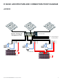
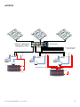
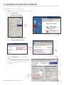
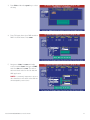
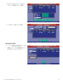
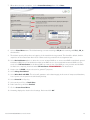
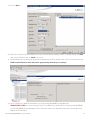
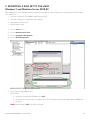
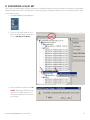
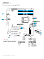
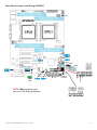
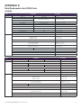
XVault xNVR200/300/400 Hardware User Guide V2.0.0 NOTICE: First and most important level of data protection starts with uninterruptable power. xVault xNVR200/300/400 User Guide V2.0.0 Seneca Data Distributors, Inc. (“Seneca”) reserves the right to make changes to the product described in this manual at any time and without notice. This product, including software and documentation, is the property of Seneca and/or its licensors, and is supplied only under a license. Any use or reproduction of this product is not allowed, except as expressly permitted by the terms of said license. In no event will Seneca be liable for direct, indirect, special, incidental, speculative or consequential damages arising from the use or inability to use this product or documentation, even if advised of the possibility of such damages. In particular, Seneca shall not have liability for any hardware, software or data stored or used with the product, including the costs of repairing, replacing, integrating, installing or recovering such hardware, software or data. Any disputes arising between manufacturer, reseller and customer shall be governed by the laws of the State of New York, USA. The State of New York shall be the exclusive venue for the resolution of any such disputes. Seneca’s total liability for all claims will not exceed the price paid for the hardware product. FCC Statement: This equipment has been tested and found to comply with the limits for a Class A digital device pursuant to Part 15 of the FCC Rules. These limits are designed to provide reasonable protection against harmful interference when the equipment is operated in a commercial environment. This equipment generates, uses, and can radiate radio frequency energy and, if not installed and used in accordance with the manufacturer’s instruction manual, may cause harmful interference with radio communications. Operation of this equipment in a residential area is likely to cause harmful interference, in which case you will be required to correct the interference at your own expense. Unless you request and receive written permission from Seneca, you may not copy any part of this document. Information in this document is subject to change without notice. Other products and companies referred to herein are trademarks or registered trademarks of their respective companies or mark Specifications subject to change without notice. All trademarks used in this document are respective of their individual corporations. xVault xNVR200/300/400 User Guide V2.0.0 2 Page I. Product Introduction........................................................................................................................................................... 5 II. Intended Audience.............................................................................................................................................................. 6 III. Best Practices....................................................................................................................................................................... 6 Network Segregation................................................................................................................................................ 6 Network IP Addressing for Camera, Viewing and Management........................................................................... 7 IP Addressing for iSCSI SAN..................................................................................................................................... 7 RAID Set Configuration Consideration & Information........................................................................................... 8 RAID Rebuild/Reconstruction Parameters............................................................................................................... 8 IV. Base Architecture And Connection Point Diagram.......................................................................................................... 9 V. Getting Started A. Drive Enclosure Slots And Trays............................................................................................................................. 12 i. Drive Tray Identification ii. Drive Tray Removal iii. Drive Tray Insertion B. Cabling & Connections........................................................................................................................................... 13 C. Remote Access to Management GUI.................................................................................................................... 15 D. Changing Camera / Viewing / Management Port IP Addresses......................................................................... 16 E. Changing iSCSI/NAS Port IP Addresses................................................................................................................ 17 F. Default Username and Password........................................................................................................................... 18 VI. RAID Management Using BIOS Control A. Entering BIOS RAID Control................................................................................................................................... 19 B. Creating A Mirrored OS Drive Pair......................................................................................................................... 20 C. BAD Drive Rebuild/Restore...................................................................................................................................... 24 Using MegaRAID Storage Manager A.Accessing RAID Manager....................................................................................................................................... 25 B. Creating RAID Sets.................................................................................................................................................. 26 C. Mounting RAID Sets to Storage Server................................................................................................................. 30 D. Expanding RAID Sets.............................................................................................................................................. 32 E. Configuring Rebuild, Reconstruction & BGI Rates............................................................................................... 34 VII. Configuring Alerts............................................................................................................................................................. 35 VIII. Support............................................................................................................................................................................... 38 Appendix A Specifications........................................................................................................................................................... 39 Appendix B Main Board connectors and jumpers..................................................................................................................... 41 Appendix C Revisions & BIOS Settings....................................................................................................................................... 44 Appendix D Field Replaceable Units (FRU) Parts....................................................................................................................... 47 xVault xNVR200/300/400 User Guide V2.0.0 3 NOTICE: First and most important level of data protection starts with uninterruptable power. An Uninterruptable Power Source (UPS) is required to protect storage data, cache battery backup is not adequate to the task of data storage protection. If this xNVR is not protected by an UPS please consult with your account representative or pre-sales engineer for assistance in correctly sizing a UPS to not only protect this xNVR but your entire IT infrastructure. xVault xNVR200/300/400 User Guide V2.0.0 4 I. PRODUCT INTRODUCTION The xVault® xNVR200, xNVR300 and xNVR400 series is Seneca’s series of rack mount security and surveillance recording servers. The 200 and 300 series are a single processor recorder family and the 400 series is a dual processor recorder family. The xVault Unified Storage series is available in five rack mount comfigurations. 2U 4 Bay 2U 8 Bay 2U 12 Bay 3U 16 Bay 4U 24 Bay All units support SAS 3g and 6g, SATA-II and III and Solid State Drives. The 2U rack form factor is available in 4, 8 and 12 bay configurations. The 3U supports up to sixteen internal hot swap drives and the 4U supports up to twenty four internal hot swap drives. The xVault xNVR’s are optionally expandable externally up to a maximum of 120 drives which is dependent on starting xNVR model. The xNVR200 group is powered with the Intel® Xeon® processor E3 quad core. The xNVR300 and 400 groups are based on the Intel® Xeon® processor E5 processor. All of the Seneca xNVR recording servers provide ample power to drive outstanding IO and bandwidth, options for more powerful higher core count processors are available to meet VMS demands. Memory options up to 256GB are also configurable. The standard units ship with two 1Gbe network ports with options to support iSCSI or NAS connectivity. Microsoft Windows graphical user interface allows easy configuration for advance features such as dynamic volume expansion, storage virtualization and same enclosure mixed tier storage support. xNVR200 xNVR300 Operating System support xNVR400 Linux, Windows 7 Professional, Server 2008 R2 CPU Intel Xeon Processor E3 Intel® Xeon® Processor E5 Dual Intel® Xeon® Processor E5 32GB 64GB standard standard 1GbE Camera LAN ports 1 1 1 1GbE Viewing & Management ports 1 1 1 ® Max memory 16GB Enhanced graphics standard Form Factor SSD OS drives option ® 2U 4 Bay, 2U 8 Bay, 2U 12 Bay, 3U 16 Bay, 4U 24 Bay option option standard standard standard standard 24 24 Max standard raw internal capacity 120TB 120TB 120TB High speed storage option option option iSCSI/NAS storage support option option option standard standard Mirrored OS standard DAS drive expansion option Max number of drives 24 Redundant Power standard xVault xNVR200/300/400 User Guide V2.0.0 5 II. INTENDED AUDIENCE The intended audience for this manual and product should have a working knowledge of server hardware, operating systems and be able to configure network interfaces, switches and cameras to requirement. Server Hardware/OS • Base server layout concepts and the ability to recognize rear connections necessary for management, network or storage connectivity. • Know different PCIe slot mechanical and electrical differences and how to apply to proper use. • Have a working knowledge of RAID concepts and application. Be able to use advanced RAID configuration utilities. • Familiarity with SATA, SAS and SSD hard drives as well as internal and external cabling requirements. • Be familiar with network connectivity and configuration of NIC cards with regard to IP addressing, teaming, jumbo frames and MTU size. • Able to read and do base level interpretation of system logs and error logs. • Have a working knowledge of how to provide outside access via the Internet for remote technical assistance. Network Hardware • Have a clear understanding of LAN/WAN infrastructure and how to plan for additional servers, cameras and network storage when required. III. BEST PRACTICES NETWORK SEGREGATION Camera LAN, Management LAN and VIEWING LAN can coexist in the same sub structure. The video management software should provide “best practice” advice as to if and when the three LAN types should be separate. Two 1GbE network ports should be used to provide path resiliency whenever possible. iSCSI/NAS storage should connect to an isolated network dedicated strictly to storage. This separation allows for best performance and protection. The standard xNVR configuration provide two 1GbE ports, a second network interface module with at least two ports should be added if iSCSI or NAS storage is to be implemented. NETWORK IP ADDRESSING FOR CAMERA, MANAGEMENT & VIEWING LAN When camera LANs are created without the use of a DHCP server, it is recommended to use one of three non-routed IP address ranges. These ranges are; 10.0.0.0 – 10.255.255.255 172.16.0.0 – 172.31.255.255 192.168.0.0 – 192.168.255.255 Servers, managed switches, directors, viewing stations or clients should consume upper IP addresses in a subnet, leaving lower IP addresses for cameras. This creates a more easily recognized separation between IT hardware and cameras. Seneca preconfigures standard LAN ports with DHCP disabled and uses starting addresses of 192.168.1.253 and 252 for the NIC ports. All servers ship with the afore mentioned default addresses. When there is more than one server installed, the network ports must be individually configured on each xNVR. The following table is provided for reference only and addresses are not required. xVault xNVR200/300/400 User Guide V2.0.0 6 Recommended xNVR Fixed IP Addresses IP Address port 0 IP Address port 1 Mask Gateway 1st Server* 192.168.1.253 192.168.1.252 255.255.255.0 192.168.1.1 2nd Server 192.168.1.251 192.168.1.250 255.255.255.0 192.168.1.1 3rd Server 192.168.1.249 192.168.1.248 255.255.255.0 192.168.1.1 4th Server 192.168.1.247 192.168.1.246 255.255.255.0 192.168.1.1 5th Server 192.168.1.245 192.168.1.244 255.255.255.0 192.168.1.1 6th Server 192.168.1.243 192.168.1.242 255.255.255.0 192.168.1.1 7th Server 192.168.1.241 192.16831.240 255.255.255.0 192.168.1.1 8th Server 192.168.1.239 192.168.1.238 255.255.255.0 192.168.1.1 9th Server 192.168.1.237 192.168.1.236 255.255.255.0 192.168.1.1 10th Server 192.168.1.235 192.168.1.234 255.255.255.0 192.168.1.1 More than 10 servers or nodes (xNVRs or management servers) requires a domain control services (server) * Default IP Addresses for all xNVR’s shipped IP ADDRESSING iSCSI SAN Seneca preconfigures the IP SAN address ports. This preconfiguration helps facilitate the connection of xVault USP and xVOS iSCSI storage arrays to the xNVR. Completely separate networks should be used when implementing an IP SAN. Seneca will always recommend or quote an extra NIC card with a minimum of two 1GbE ports per server when cognoscente of the desire or requirement to support IP SAN storage. The IP SAN should be isolated from general LAN or Camera LAN traffic either by “VLAN”ing in a switch or with a separate switch. This isolation allows storage to perform as designed and adds a certain level of protection from external attack. Recommended XNVR Fixed IP Addresses for 1GbE IP (iSCSI) SAN IP Address port 2 IP Address port 3 Mask Gateway 1st Server* 10.0.10.254 10.0.10.253 255.255.255.0 none 2nd Server 10.0.10.252 10.0.10.251 255.255.255.0 none 3rd Server 10.0.10.250 10.0.10.249 255.255.255.0 none 4th Server 10.0.10.248 10.0.10.247 255.255.255.0 none 5th Server 10.0.10.246 10.0.10.245 255.255.255.0 none 6th Server 10.0.10.244 10.0.10.243 255.255.255.0 none 7th Server 10.0.10.242 10.0.10.241 255.255.255.0 none 8th Server 10.0.10.240 10.0.10.239 255.255.255.0 none 9th Server 10.0.10.238 10.0.10.237 255.255.255.0 none 10th Server 10.0.10.236 10.0.10.235 255.255.255.0 none More than 10 servers does not require a domain server for the IP SAN storage * Default iSCSI IP address for all xNVR’s shipped xVault xNVR200/300/400 User Guide V2.0.0 7 RAID SET CONFIGURATION CONSIDERATION & INFORMATION Best RAID5 or RAID6 performance is when the drive count in a RAID set is between 12 and 24 drives. Eight drives in a RAID5/6 should be considered the lowest drive count when IO and transfer rates are above anything but the most basic. When drive counts in a RAID set are below five, it is highly recommended to use RAID10. If the capacity is low enough a mirrored (RAID1) solution using SSD drives can be considered as a higher performance option without extravagant expense. Please consult with your account representative. Unless otherwise specified, Seneca’s policy is to provide RAID5 when using less that 18 drives in the set. Eighteen to twenty four drives will default to RAID6. The xNVR series may be optionally configured to support direct attached external storage. This provides better performance than network storage (iSCSI or NAS) at a significantly lower price point. RAID REBUILD/RECONSTRUCTION PARAMETERS Seneca leaves the rebuild and reconstruction parameters on the RAID controller at a factory default of 30% of total IO and Bandwidth consumption. Customer preference of restore of defective drive versus impact on array performance which can result in frame drops is subjective. In house testing shows that with Rebuild and Reconstruction rates set to 20%. A replacement drive will rebuild at a rate of no more than 2.22 hours per terabyte for the drive being restored. APPROXIMATE RAID MEMBER REBUILD TIME Drive Size Four or Eight Drive RAID Set 1TB 2.22 hours 2TB 4.44 hours 3TB 6.66 hours 4TB 8.88 hours 5TB 11.1 hours 6TB 13.32 hours xVault xNVR200/300/400 User Guide V2.0.0 8 IV. BASIC ARCHITECTURE AND CONNECTION POINT DIAGRAM xNVR200 Catalyst 3560 1 SYST RpS Camera, Viewing and Management LANs STAT DUpLx SpEED pOE 2 3 4 5 6 7 8 9 10 11 12 13 14 15 16 1X 17 18 19 20 21 22 23 24 25 26 27 28 29 30 31 32 33 34 35 36 37 38 39 40 41 42 43 44 45 46 47 SERIES PoE-48 SERIES PoE-48 SERIES PoE-48 48 15X 17X 31X 33X 47X 16X 32X 34X 48X 1 3 2 2X 18X 4 MODE Catalyst 3560 1 SYST RpS STAT DUpLx SpEED pOE 2 3 4 5 6 7 8 9 10 11 12 13 14 15 16 1X 17 18 19 20 21 22 23 24 25 26 27 28 29 30 31 32 15X 17X 33 34 35 36 37 38 39 40 41 42 43 44 45 46 47 48 31X 33X 47X 1 3 2 16X 2X 18X 32X 34X 4 48X pOE Switch Stack MODE Catalyst 3560 1 SYST RpS STAT DUpLx SpEED pOE 1X 2X 2 3 4 5 6 7 8 9 10 11 12 13 14 15 16 17 15X 17X 16X 18X 18 19 20 21 22 23 24 25 26 27 28 29 30 31 32 33 31X 33X 32X 34X 34 35 36 37 38 39 40 41 42 43 44 45 46 47 48 47X 1 3 2 4 48X MODE To: remote management and viewing stations Up DOWN iSCSI SAN Switch or Switch VLAN MODE CONSOLE SYST XPS STAT SPEED DUPLX BLANK MODULE FN 1X 11X 13X 2X 12X 14X Catalyst 3560-X Series Up DOWN Direct Attached Storage Expansion Up iSCSI SAN Storage xVault xNVR200/300/400 User Guide V2.0.0 9 xNVR300 Catalyst 3560 SYST RpS Camera, Viewing and Management LANs STAT DUpLx SpEED pOE 1 2 3 4 5 6 7 8 9 10 11 12 13 14 15 16 1 2 3 4 5 6 7 8 9 10 11 12 13 14 15 16 1X 17 18 19 20 21 22 23 24 25 26 27 28 29 30 31 32 17 18 19 20 21 22 23 24 25 26 27 28 29 30 31 32 15X 17X 33 34 35 36 37 38 39 40 41 42 43 44 45 46 47 48 33 34 35 36 37 38 39 40 41 42 43 44 45 46 47 48 31X 33X SERIES PoE-48 SERIES PoE-48 SERIES PoE-48 47X 1 3 2 16X 2X 18X 32X 34X 4 48X MODE Catalyst 3560 SYST RpS STAT DUpLx SpEED pOE 1X 15X 17X 31X 33X 47X 1 3 2 16X 2X 18X 32X 34X 4 48X pOE Switch Stack MODE Catalyst 3560 1 SYST RpS STAT DUpLx SpEED pOE 1X 2X 2 3 4 5 6 7 8 9 10 11 12 13 14 15 16 17 15X 17X 16X 18X 18 19 20 21 22 23 24 25 26 27 28 29 30 31 32 33 31X 33X 32X 34X 34 35 36 37 38 39 40 41 42 43 44 45 46 47 48 47X 1 3 2 4 48X MODE To: remote management and viewing stations Up DOWN iSCSI SAN Switch or Switch VLAN MODE CONSOLE SYST XPS STAT SPEED DUPLX BLANK MODULE FN 1X 11X 13X 2X 12X 14X Catalyst 3560-X Series Up DOWN Direct Attached Storage Expansion Up iSCSI SAN Storage xVault xNVR200/300/400 User Guide V2.0.0 10 xNVR400 Catalyst 3560 SYST RpS Camera, Viewing and Management LANs STAT DUpLx SpEED pOE 1 2 3 4 5 6 7 8 9 10 11 12 13 14 15 16 1 2 3 4 5 6 7 8 9 10 11 12 13 14 15 16 1X 17 18 19 20 21 22 23 24 25 26 27 28 29 30 31 32 17 18 19 20 21 22 23 24 25 26 27 28 29 30 31 32 15X 17X 33 34 35 36 37 38 39 40 41 42 43 44 45 46 47 48 33 34 35 36 37 38 39 40 41 42 43 44 45 46 47 48 31X 33X SERIES PoE-48 SERIES PoE-48 SERIES PoE-48 47X 1 3 2 16X 2X 18X 32X 34X 4 48X MODE Catalyst 3560 SYST RpS STAT DUpLx SpEED pOE 1X 15X 17X 31X 33X 47X 1 3 2 16X 2X 18X 32X 34X 4 48X pOE Switch Stack MODE Catalyst 3560 1 SYST RpS STAT DUpLx SpEED pOE 1X 2X 2 3 4 5 6 7 8 9 10 11 12 13 14 15 16 17 15X 17X 16X 18X 18 19 20 21 22 23 24 25 26 27 28 29 30 31 32 33 31X 33X 32X 34X 34 35 36 37 38 39 40 41 42 43 44 45 46 47 48 47X 1 3 2 4 48X MODE To: remote management and viewing stations Up DOWN iSCSI SAN Switch or Switch VLAN MODE CONSOLE SYST XPS STAT SPEED DUPLX BLANK MODULE FN 1X 11X 13X 2X 12X 14X Catalyst 3560-X Series Up DOWN Direct Attached Storage Expansion Up iSCSI SAN Storage xVault xNVR200/300/400 User Guide V2.0.0 11 V. GETTING STARTED A. Drive Enclosure Slots And Trays Operating System (OS) drives are not front side hot swap accessible. 2U enclosures have the operating system disk mounted internally. 3U and 4U drives are rear mounted and hot swappable. The operating system drive may or may not come as a mirrored pair, this is dependent on standard configuration and option availability. Removable drives are installed beginning with SLOT 1 and continuing sequentially until all drive bays are filled. Drives installed from the factory will be in groups of performance. Meaning, Solid State Drives will be installed first, followed by 15k RPM drives, followed by 10k RPM drives then 7200 RPM drives. Future addition of drives does not require reordering drives; it is advised that additional drives be added in order of performance. SSD and 7200 RPM drives are available with SATA interfaces, never mix SAS and SATA drives in the same RAID set or group. xNVR 2U 4 BAY xNVR 3U 16 BAY SLOT-0 SLOT-1 SLOT-3 SLOT-2 xNVR 2U 8 BAY SLOT-0 SLOT-1 SLOT-2 SLOT-3 SLOT-4 SLOT-5 SLOT-6 SLOT-7 SLOT-1 SLOT-2 SLOT-3 SLOT-4 SLOT-5 SLOT-6 SLOT-7 SLOT-8 SLOT-9 SLOT-10 SLOT-11 SLOT-12 SLOT-13 SLOT-14 SLOT-15 SLOT-16 SLOT-3 SLOT-4 xNVR 4U 24 BAY SLOT-1 xNVR 2U 12 BAY SLOT-2 SLOT-5 SLOT-6 SLOT-7 SLOT-8 SLOT-9 SLOT-10 SLOT-11 SLOT-12 SLOT-1 SLOT-2 SLOT-3 SLOT-4 SLOT-13 SLOT-14 SLOT-15 SLOT-16 SLOT-5 SLOT-6 SLOT-7 SLOT-8 SLOT-17 SLOT-18 SLOT-19 SLOT-20 SLOT-9 SLOT-10 SLOT-11 SLOT-12 SLOT-21 SLOT-22 SLOT-23 SLOT-24 i.DRIVE TRAY IDENTIFICATION All drive trays shipped from the factory will have a slot number ID affixed to the top front. Trays will be labeled whether drives are installed or not. xVault xNVR200/300/400 User Guide V2.0.0 12 ii.REMOVING DRIVE TRAY Press “Lever Release Button”. The tray “Extraction/Insertion Lever” will pop out on the right side. Gently rotate the lever outward and at the same time cradle the drive tray underneath with your free hand. When the drive lever is fully extended, slide the drive tray out of the enclosure. Lever Release Button Extraction/Insertion Lever iii.INSERTING DRIVE TRAY Match tray number to enclosure slot number. With the lever fully extended, slowly slide the tray into the slot until lever engages enclosure. Gently push drive lever in, the tray should slide into the enclosure without significant force on the lever or tray. Push lever in until the lever release button locks, there should be a distinct “click” when this happens. If the lever does not move in at corresponding rate as the tray slides into the enclosure, STOP! Pull the tray back out and try again. When the tray is correctly installed it should be flush with all other trays in the enclosure. NEVER move the tray in fast or force the lever to close. Damage will occur to the tray and possibly to the drive connector. B. CABLING & CONNECTION XNVR video recorder appliances come in three form factors but all use common components and cabling points. There are only six main cabling groups; • Power • Monitor/Keyboard/Mouse • Camera/Viewing/Management Network • iSCSI/NAS Network (option) • RAID Expansion Port (option on some models) POWER CORDS All xVault storage appliances come with redundant hot swap power supplies. Each power supply requires its own power cord. The power cords supplied are standard 115VAC machine cords. Care should be taken to always route AC power cords away from cables that transmit data. It is also recommended that each power cord have a separate electrical path back to the facility service entrance. Meaning each power cord should be connected to separate circuit breakers. It is also prudent to have at least one of the power cords connected to an uninterruptable power source. xVault xNVR200/300/400 User Guide V2.0.0 13 REAR SIGNAL CABLE LOCATIONS xNVR200 Exp. Ser. Mgmt. 12/16/24 Bay Only RAID Expansion Port iSCSI/NAS Ports iSCSI/NAS Ports Exp. Ser. Mgmt. 12/16/24 Bay Only PCIe x8 Optional Card Graphics Card DVI-I Optional 10 GbE NIC Port Exp. Ser. Mgmt. 12/16/24 Bay Only iSCSI/NAS Ports Graphics Card DVI-I PCIe x8 Optional Card HDMI USB 4 HDMI USB 2 RAID Controller RAID Controller USB 3 RAID Expansion Port Option Port 0 RAID Controller Port 3 IPMI 14 xVault xNVR200/300/400 User Guide V2.0.0 Do Not Use USB 1 Port 1 Port 2 Port 3 RAID Expansion Port USB 4 Viewing and Management LAN Camera LAN Port 1 USB 2 Graphics Card USB 4 Port 0 USB 3 DVI-I USB 2 Optional Analog Capture Card IPMI Port 3 IPMI Port 2 Viewing and Camera Management LAN LAN HDMI USB 3 Do Not Use USB 1 Port 1 Port 0 USB 1 Do Not Use Port 2 Viewing and Camera Management LAN LAN xNVR300 xNVR400 Note: 2U depicted, 3U, and 4U have same connector and option locations, only the height of the PCIe cards is different. MONITOR, KEYBOARD & MOUSE CONNECTIONS A single video monitor may be connected to the HDMI OR DVI connector but not both. The two denoted USB ports are used for keyboard and mouse connection. These ports are KVM compatible. CAMERA/VIEWING/MANAGEMENT NETWORK CONNECTIONS The xNVRs use standard Cat 6 cabling. The xNVR’s come standard with two 10/100/1000 802.11 network ports. The ports ship from the factory with the following fixed IP addresses; IP ADDRESS MASK GATEWAY Port 0 192.168.1.253 255.255.255.0 192.168.1.1 Port 1 192.168.1.252 255.255.255.0 192.168.1.1 NOTE: Each xNVR on the network must have a unique IP address. ISCSI/NAS NETWORK CONNECTIONS iSCSI and NAS connections use standard Cat6 cabling. The xNVR can be optionally equipped to support iSCSI/NAS external storage appliances. iSCSI IP SAN storage requires the SAN be isolated for any other LAN or WAN. As such separate 1GbE ports are supplied to support the IP SAN. It is highly recommended to use fixed non-routable IP addresses to support the IP SAN. For customer convenience, the ports have the following default settings. IP ADDRESS MASK GATEWAY Port 2 10.0.10.254 255.255.255.0 blank Port 3 10.0.10.253 255.255.255.0 blank NOTE: Each IP SAN member on the storage area network must have a unique IP address. RAID EXPANSION PORT CONNECTION The xNVR can be optionally equipped with the ability to expand using direct attached storage enclosures. Up to four external drive enclosures are supported. The interconnect cable used is an industry standard SFF-8088 to SFF-8088 cable. External chassis supplied by Seneca come with the cable to connect to the xNVR. C. REMOTE ACCESS TO THE MANAGEMENT GUI All xNVRs have the ability to be remotely accessed for management. This is accomplished by using the Remote Desktop Connection services. Any PC or Desktop running a Microsoft Operating System that is connected to the same subnet or directly connected to a Camera/Viewing/Management Port 0 can remotely access the xNVR Open the PC/laptop Remote Desktop Connection and enter the xNVR IP address as shipped from the factory. You will be prompted for the username and password of the system. Upon successful entry the standard OS window will appear and navigation can proceed as if using a directly attached monitor and keyboard. xVault xNVR200/300/400 User Guide V2.0.0 15 D. CHANGING CAMERA/VIEWING/MANAGEMENT PORT IP ADDRESSES Port attributes are accessed as follows; Click on Start button located on the bottom left corner of the display. 1. Click on Control Panel 2. Click on Network and Internet 1 2 3. Click on Network and Sharing Center 4. Click on Change Adaptor Settings 3 4 5. Select the Camera or View_Mgmt port to be reviewed or changed 5 6. Select Internet Protocol Version 4 (TCP/Ipv4) 7. Review or change IP information for the selected port. NOTE: Each Port must have a unique IP Address and the same mask. Setting or features must be set the same for each port. 7 6 xVault xNVR200/300/400 User Guide V2.0.0 16 E. CHANGING iSCSI/NAS PORT ATTRIBUTES For iSCSI implementation it is highly recommend to leave the iSCSI ports at the factory shipped static IP port addresses. NIC port attributes are accessed as follows; Click on Start button located on bottom left corner of display. 1. Click on Control Panel 2. Click on Network and Internet 1 2 3. Click on Network and Sharing Center 4. Click on Change Adaptor Settings 3 4 5. Select the iSCSI/NAS port to be reviewed or changed 5 6. Select Internet Protocol Version 4 (TCP/Ipv4) 7. Review or change IP information for the selected port. 7 6 xVault xNVR200/300/400 User Guide V2.0.0 17 F. DEFAULT USERNAME AND PASWORD The system ships with two default users. Both share the same password and can be changed per policy. Username: Administrator Password: P@ssw0rd Username: NVR_Service Password: P@ssw0rd xVault xNVR200/300/400 User Guide V2.0.0 18 VI. RAID MANAGEMENT The intent of this section is to provide guidance in the creation and expansion of RAID sets within the xNVR and direct attached expansion chassis. The xNVR200, 300 and 400 families connect the OS drive to the embedded motherboard RAID controller. The VMS application(s) also reside on the OS drive. Depending on appliance purchased and options selected the OS drive may consist of a mirrored pair. In the cases where the OS drive is mirrored it is recommended that base management functions be done using the BIOS RAID controller tools. The BIOS RAID controller tools are accessed by simultaneously hitting the Ctrl and M keys during power up while the following screen is displayed on the console monitor. It is recommended that the BIOS tools only be used for OS drive mirror set creation and rebuild/restore of a defective drive. To this end only creation and rebuild/restore will be covered in this manual. All other functions, including rebuild/ restore, can be done via the MegaRAID Software Manager (MSM) which can be found and launched from the Windows operating system desktop. Instruction for use of the MSM can also be found in this manual. The xNVR200, 300 and 400 families with 8 or more disk bays are supplied with a PCIe RAID controller. This PCIe RAID controller maintains the array(s) that contain the video stream data and archives. Since the arrays can only be accessed while an operating system is intact and operational and because control of the arrays is easier using the MegaRAID Software Manager (MSM) software, only the MSM will be covered by this manual for PCIe based disks and arrays. USING BIOS CONTROL FOR MIRRORED DRIVE SETS ONLY A. ENTERING BIOS RAID CONTROL MENU 1. Power up system 2. During power up self-test wait for the following screen to appear. Immediately and simultaneously press the Ctrl and M keys to enter the BIOS RAID routine. xVault xNVR200/300/400 User Guide V2.0.0 19 When the following screen appears, the BIOS RAID control has successfully been entered. NOTE: DO NOT select Ctrl and H, this is not the OS drive RAID control screen. Major damage to existing video can occur. B. CREATING A MIRRORED OS DRIVE PAIR REMEMBER the system ships from Seneca with the operating system installed. This section is only provided in the event recovery from a catastrophic event that destroyed the entire mirrored disk pair is required. 1. From the management screen select Configure and Easy Configuration 2. From the ARRAY SELECTION MENU use the up and down arrows to select the two drives for the mirror set. Use the space key to lock the desired drives. xVault xNVR200/300/400 User Guide V2.0.0 20 3. Press F10 and then the space key to select the array 4. Press F10 again, then select RAID and then RAID 1 from the menu. Press enter 5. Navigate to Units, hit enter and make selection and hit enter. Navigate to DWC and select On and hit enter. This will enable write back cache for the OS disk and VMS application NOTE: It is extremely important to protect drive data that is write back caches with an uninterruptable power source xVault xNVR200/300/400 User Guide V2.0.0 21 6. When finished with above configuration, navigate to Accept and press enter 7. Press esc, select Yes and hit enter INITIALIZE DRIVE 8. From the Management Menu select Initialize and then the Virtual Drive where the RAID1 set was just created. xVault xNVR200/300/400 User Guide V2.0.0 22 9. Press F10 to bring up Initialize confirmation and select Yes then press enter 10. Virtual drive initialization will begin and progress will be indicated by the bar. When initialization is complete press esc. Do not press esc until after the initialization is complete 11. From the Management Menu screen, select Configure, select Select Boot Drive and then select the mirrored drive pair created and initialized by pressing enter. Press any key to continue. Press the system reset button or power fail the system After RAID set creation, initialization and boot select is complete, the drive virtual drive (RAID1 mirror set) will appear in the boot BIOS for selection as a target. Restore OS and applications to virtual drive and boot system. xVault xNVR200/300/400 User Guide V2.0.0 23 C. BIOS LEVEL BAD DRIVE REBUILD/RESTORE 1. Enter the Management Menu via Ctrl and M as described earlier in this manual. 2. Select Rebuild. Identify the defective drive. If the bad drive is installed in an internal fixed position as is the case with the 4 bay, 8 bay, and 12 bay configurations, power down the system and replace the defective drive, power up and return to this screen display. If the OS drive is hot swap removable, then replace the defective drive. 3. Select the defective drive position and hit space. Press F10. When prompted select Y to start the rebuild/restore to the replacement drive. After the rebuild is complete, press any key to continue. xVault xNVR200/300/400 User Guide V2.0.0 24 USING MegaRAID STORAGE MANAGER A. ACCESSING RAID MANAGER Select MegaRAID Storage Manager icon on desktop. 1. Click on IP Address hyperlink of the system to be managed. 2. Log on using the same administrative username and password as used to login into the xNVR The RAID Controller Management Utility screen will now display. xVault xNVR200/300/400 User Guide V2.0.0 25 B. CREATE A RAID SET All xNVR’s ship from the factory with RAID sets built per customer specification. This chapter is provided in the event a new RAID set is to be built or a previously built RAID set is purposely destroyed to create a different RAID set. This process involves creating a “Drive Group”, a virtual drive as it relates on to this RAID controller, Selecting the drives to be in the virtual drive (RAID Set) and RAID set attributes, initializing the virtual drive (RAID set), assigning a volume type, formatting the drive at an OS level and assigning a drive letter for the OS. 1. Select Create a Virtual Disk or stacked volume icon illustrated below. xVault xNVR200/300/400 User Guide V2.0.0 26 2. Select Create A Virtual Drive, check Advanced and click on Next 3. Select “RAID Level from drop down. In this case RAID5 has been selected. The selection will vary depending on requirements or preference. 4. Do not select a Security Method. Do not Select Power Save Mode. 5. Highlight a single unconfigured drive and click on add to add to drive group. CAUTION: Select only the same part number drive for a single drive group (RAID set). Mixing of different drive part numbers, different drive interfaces, drive speeds (15k 10k or 7200 RPM) or capacities may result in poor performance or unreliable operation. You can use the slide bar to view complete drive information. 6. Continue selecting drives until desired number of drives for the RAID set is complete. NOTE 1: The total number of drives includes the parity drives for RAID5 and RAID6. NOTE 2: This creation process is only true for RAID0, 1, 5 and 6. NOTE 3: The selection of drives is for the RAID set only. It does not include hot or global spares. That is done in a separate process. NOTE 4: The maximum number of drives that can be selected in a single RAID set is 32. xVault xNVR200/300/400 User Guide V2.0.0 27 7. When drive selection is complete, click on Create Drive Group then click on Next. 8. Select a Virtual Drive name. The default naming convention starting at VD_0 and continuing with VD_1, VD_2… should suffice. 9. The default capacity reflects the total capacity of the virtual drive being created. This should be default. Smaller capacities can be created later when iSCSI volumes are being created for host assignment later. 10. Select No Initialization when it is desired to recover an intact RAID set or create a new RAID set with back ground initialization (BGI) Select Fast Initialization when a new RAID set is to be created and instant use RAID set is desired. Select Full Initialization for the fastest RAID set creation. Use of the RAID set is not possible until the RAID Set has been completely initialized under Full Initializaton. RECOMMENDED: Full Initialization 11. A stripe size of 256KB is a best selection for general IT purposes. 12. Select Always Read Ahead 13. Select Write Back with BBU. This select will guarantee cache data integrity in the event of unexpected shutdown, loss of power or non-operational cache battery backup. 14. Select Direct IO for IO policy 15. Select an Access Policy of Read Write 16. Disk Cache Policy should be Enabled 17. Click on Create Virtual Drive 18. A warning displayed to double check settings. Review and click OK xVault xNVR200/300/400 User Guide V2.0.0 28 19. Click on Next 20. The next screen will review the RAID set policies selected. Review carefully, if there is a wrong setting, click Back and correct. Otherwise click on Finish to proceed. 21. The initialization process will begin. Monitor the initialization process by clicking on the clock icon on the main screen. RAID set initialization for hard disks takes approximately 60 minutes per terabyte. 22. Upon completion of RAID set virtualization you may exit the MegaRAID Storage Manager. PRODUCTIVITY HINT: It is not necessary to wait for one RAID set to initialize before creating a new Disk/RAID Set. The MegaRAID Storage Manager will also allow the return to modify Disk Groups while other Disk Group/ RAID Sets are initializing. xVault xNVR200/300/400 User Guide V2.0.0 29 C. MOUNTING A RAID SET TO THE xNVR Windows 7 and Windows Server 2008 R2 After a RAID set is created and initialized it must then be mounted to the storage server operating system. This entails four operations; • Selection of partition style (MBR or GUID Partition GPT) • Creation of disk type—Simple Disk is the default • Assignment of Drive Letter • Quick format of disk 1. Click on Start button 2. Click on Administrative Tools 3. Click on Computer Management 4. Click on Disk Management 5. Select partition type MBR or GPT. Choice Help: a. If partition is larger than 2TB than select GPT b. If partition is to be used as a boot partition for iSCSI, it must be smaller than 2TB and have a MBR partition style. NOTE: In this example, GPT style will be selected xVault xNVR200/300/400 User Guide V2.0.0 30 6. Right click on unallocated storage and select New Simple Volume 7. Click Next on the first screen of the Welcome To The New Simple Volume Wizard 8. Specify the maximum capacity on the Specify Volume Size screen. Later we will be able to create smaller volumes to present to server hosts. 9. On Assign Drive Letter Or Path screen, select appropriate drive letter and click on Next 10. Select the red circled defaults. On the Volume Label make selection that means something to the recorder server appliance. The simple reinforcement of the actual letter. If the underlying RAID set is special make note in the name; “Drive_E 15k” or “SQL” 11. Click on Next after selections are made and data entered. 12. Review selections, if correct click on Finish, if changes are to be made click on Back. After a brief “formatting” status flash the new drive will return as a Healthy Partition xVault xNVR200/300/400 User Guide V2.0.0 31 D. EXPANDING A RAID SET This is not a recommended procedure. Expansion of a RAID set impacts online performance tremendously. Expanding a RAID set while video data is being written to the array greatly extends the expansion process and puts present data recoverability in peril. 1. Open MegaRAID Storage Manager 2. Click on Logical tab. Right click on Drive Group that will be expanded. Click on Modify Drive Group. 3. Check confirm box and click on Yes ALERT: Expanding a RAID set may cause irrecoverable data loss. It is advised to backup the drive before proceeding. xVault xNVR200/300/400 User Guide V2.0.0 32 4. Take care to match the RAID set type field to match the Drive Group being expanded. 5. Select the same drive size that is next in the physical sequence drive slot. This example has a Slot 21 drive being added to RAID Group 1 that ended at slot 20. Click on Next 6. Review and click on Finish if information is correct. Click on Back if changes are necessary. xVault xNVR200/300/400 User Guide V2.0.0 33 7. The system will issue a confirmation request one more time. Click Yes to continue. CAUTION: The expansion of a RAID set, even if only a single drive will take as long if not longer than the initial RAID build. It is Seneca’s recommendation that RAID expansions only be done at a one, two or three drive count with NO data activity from the system. A new RAID set should be considered as an alternative for four or more drives. E. CONFIGURING REBUILD, RECONSTRUCTION and BGI RATES 1. Open MegaRAID Storage Manager 2. Right click on RAID controller holding the array. Select Set Adjustable Task Rates. Change tasks percentages. Percentages represent a portion of total array performance. So a Rebuild Rate of 50% will detract 50% of the arrays available performance to process video streams. In turn the RAID set will rebuild faster than if set to 10%. REBUILD & RECONSTRUCTION RATE This is the rate at which a replacement drive will rebuild as a percentage of total IO and bandwidth available to the array. A lower percentage will take longer for the replacement drive to fully restore. However this slower rebuild rate will be less likely to impact video stream writes. A higher percentage will complete the replace drive restore faster but create a stronger possibility of lost video and would be presented as missed frames. Rebuild and Reconstruction rates should be set at the same percentage. PATROL RATE Patrol is a function of the RAID controller to check RAID set integrity. Patrol Reads do impact the arrays performance. There is another RAID set integrity check called “Check Consistency”. Leaving “Check Consistency” in place and reducing Patrols to zero will suffice in maintaining array integrity. BGI RATE Is the rate at which a new RAID set will initialize while other IO operations are in place. Setting this value to an extreme low may be tempting. But consider if a RAID set would take 12 hours to initialize without any external IO, it would take 60 hours to initialize with a setting of 20% and consistent external IO influence. xVault xNVR200/300/400 User Guide V2.0.0 34 CHECK CONSISTENCY RATE Check Consistency is a RAID controller data integrity check function. It is not advisable to completely stop consistency checks or to reduce to below 10%. VII. CONFIGURING ALERTS The xNVR series has the ability to send out RAID array status alerts via email. The ability to transmit alerts requires an inmanagement subnet SMTP server or to be routed to the SMTP server. Please consult with the network administrator for SMTP network information and access. The alerts subsystem supports four levels of alert. Fatal which is the catastrophic failure of a component within the RAID subsystem. Critical alerts are flagged when the subsystem cannot sustain another failure without high probably of going down. Warnings are issued when non-critical errors are detected/recorded. Informational alerts are issued when there are changes in configuration, login or orderly processes occurring such as system shutdown or startup. Each of the alert levels are notification configurable. There are four methods that an alert can be delivered; Supported operating System Log, system monitor Pop Up, MSM Log and/or Email. ALERT TRIGGERS ALERT 2U 4 Bay 2U 8 Bay 2U 12 Bay 3U 16 Bay 4U 24 Bay Chassis Fan Failure X X X Power Supply Failure (redundant configurations only) X X X Thermal X X X X X X Drive Failure and Unordinary Status X X RAID Set Integrity Issues X X Any Array or Array Controller Status Change X X X configurable configurable configurable In addition to basic alert level conveyance via four vehicles, specific Individual Events can have the delivery method changed. External expansion chassis with 2U 12 Bay, 3U 16 Bay or 4U 24 Bay configuration will also report same xNVR alert triggers via email. xVault xNVR200/300/400 User Guide V2.0.0 35 SETTING ALERT LEVELS AND DELIVERY METHOD Login to MegaRAID Storage Manager from desktop. Username and Password must come from an account with administrative privileges. Click Alert Settings. The selection of any of the Severity Levels will bring up the alert method configuration window. Any or all selection can be used for four different severity levels. Best practice would be to leave at default levels. From The alerts tab screen it is also possible to drill down on notification method for individual alerts by selecting Change Individual Events …, selecting individual event, then delivery method(s) and closing. xVault xNVR200/300/400 User Guide V2.0.0 36 CONFIGURING SMTP MAIL SERVER AND EMAIL RECIPIENT Login to MegaRAID Storage Manager from desktop. Username and Password must come from an account with administrative privileges. Select Tools and then Monitor Configure Alerts Select Mail Server tab and enter information Sender email address can be used to reflect identity of xNVR sending alert • Characters preceding “@” can be Alpha Numeric, the only special character allowed is “_” • Characters after “@” can be Alpha Numeric only, no special characters • The format must subscribe to email format and only use the “.com” suffix SMTP Server may be entered as a URL or IP Address IP SMTP standard Port is 25. This may be changed by deselecting Use Default Authentication is supported by checking This server requires authentication and filling in appropriate User Name and Password Select Email tab and enter recipient information New recipient email address should use standard email address format. Click Add to enter in stored table. Test will send a brief email message to all recipients in the email table. Use the control to ensure all recipients email addresses are valid and the SMTP configuration is correct. Use Save Backup to guarantee all Configure Alerts settings are saved. The Save Backup feature allows for multiple and different setting to be saved. If only one configuration is use the MSM will hold that configuration until changed. Load Backup allows the loading of different previously save alerts to be restored. It would be considered a best practice to save all alert configurations. Click OK to set alert configuration information. xVault xNVR200/300/400 User Guide V2.0.0 37 VIII. SUPPORT The xNVR video recording appliances come standard with a 3 year Next Business Day onsite warranty. Included with the warranty is advance replace of FRU parts, 8 AM to 6PM technical phone support Monday through Friday and 24x7 problem logging. INFORMATION NEEDED BEFORE CALLING FOR SUPPORT 1. Model Number 2. Serial number of unit (located on top front left cover of enclosure) 3. Contact Information (company name, contact, phone, email) 4. Description of problem (including any pop up information) 5. History or timeline of problem or use ADDITIONAL HELPFUL INFORMATION 6. Operating system log information 7. MegaRAID log information Normal Business Hours Monday through Friday 8AM–6PM Eastern 800-227-3432 #5 [email protected] Outside Normal Business Hours 888-227-9994 Next Business Day (“NBD”) Onsite support is defined as; Onsite support personnel will be dispatched in coordination with replacement parts arriving onsite to arrive the next business day after initial call log. A best effort is made to accomplish a next business day time frame. However there are unmitigated circumstances where NBD service cannot be provided. Some reasons are, but not limited to; calls logged after shipping cut off times, calls logged after business hours, weather or catastrophe related events, unusual parts outages. CALL RESPONSE EXAMPLES Tech & Parts Arrive Call logged M-F 8AM-3PM Eastern Call and troubleshooting before done shipping cutoff NBD Call logged Friday 4PM Eastern Likely miss of shipping cutoff Arrive Tuesday Call logged Monday 6:01 PM Eastern After business hours Arrive Wednesday Call logged on weekend After business hours Arrive Tuesday Call logged on Labor Day Not considered normal business hours Arrive Wednesday Call logged day after Thanksgiving Seneca holiday Arrive Tuesday New Year’s Day, Memorial Day, July 4th, Labor Day, Thanksgiving and the following day, Christmas Eve and Christmas Day are not considered business days. In addition Seneca may designate an additional two floating holidays which are also not considered business days. Please consult the Seneca website for current year’s holidays. xVault xNVR200/300/400 User Guide V2.0.0 38 APPENDIX A Specifications 2U 4 Bay 2U 8 Bay Form Factor 2U Camera Viewing Mgmt Interfaces Two 1Gbe ports iSCSI/NAS Interface (option) 10Gbe Support1 (option) Two to four 1GbE Ports Dual SFP+, Dual RJ45 Cat6a or Single CXA4 Options Maximum Internal Drives Four 3.5" Drives Eight 3.5" Drives Externally Expandable (option) Up to 52 drives Up to 56 drives Drive Compatibility SAS 3g, SAS 6g, SATA-I, SATA-II and SATA-III (6g) RAID Level Support 0, 1, 10, 5, 6, 50, 60 & JBOD Video Cache Backup Hold Time Total Expanded Raw Capacity (option) 30 days 208TB 224TB Practical Max. Single Volume Size Windows 64TB / Linux 32TB Separate OS & Application Disks Yes Mirrored OS drive option Yes Drive Level Encryption for Array (option) Dimensions (w x h x d) Weight Power Yes – Industry term applied is “At Rest Drive Encryption” 19 x 3.5 x 22.7 in. / 482.6 x 88.8 x 575.4 mm 19 x 5.25 x 27.5 in. /482.6 x 133.35 x 700 33lb / 15kg with power supply and rails 70lb / 31.7kg with power supply and rails 40lbs / 18kg with drives 95lbs / 43kg with drives Single 460 watt or Dual Load balance hot swap redundant Dual Load balance hot swap redundant 800 watts 80+ efficiency rating 650 watts 80+ efficiency rating AC Input VAC Frequency 100VAC – 240VAC 100VAC – 240VAC 47 – 63 Hz 47 – 63 Hz BTU /hr. 1570 for 460w, 2217 of 650w 2730 Operating / Non-Operating Temp 00C to 400C / 00C to 500C 00C to 400C / 00C to 500C Operating & Non-Operating Humidity 5 to 90% non-condensing 5 to 90% non-condensing Warranty 3 year onsite NBD for hardware & software with 24x7 phone support 1 Requires removal of graphics viewing option. Specifications subject to change without notice. All trademarks used in this document are respective of their individual corporations. xVault xNVR200/300/400 User Guide V2.0.0 39 Form Factor Camera Viewing Mgmt Interfaces 2U 12 Bay 3U 16 Bay 4U 24 Bay 2U 3U 4U Two 1GbE – RJ45, Port 0 for Camera LAN Port 1 for Viewing and Management iSCSI/NAS Interface (option) Two to four 1GbE Ports 10Gbe Support (option) Dual SFP+, Dual RJ45 Cat6a or Single CXA4 Options 1 Maximum Internal Drives Externally Expandable Twelve 3.5" Drives Sixteen 3.5" Drives Twenty Four 3.5" Drives Up to 60 drives Up to 80 drives Up to 120 Drive Compatibility SAS 3g, SAS 6g, SATA-I, SATA-II and SATA-III (6g) RAID Level Support 0, 1, 10, 5, 6, 50, 60 & JBOD Video Cache Backup Hold Time 30 days Total Expanded Raw Capacity 240TB 320TB Practical Max. Single Volume Size Windows 64TB / Linux 32TB Separate OS & Application Disks Yes Mirrored OS drive option Yes Drive Level Encryption for Array (option) 480TB Yes – Industry term applied is “At Rest Drive Encryption” Dimensions (w x h x d) 19 x 3.5 x 27.5 in 19 x 5.25 x 27.5 in. 19 x 7 x 27.5 in. 482.6 x 88.8 x 700 mm 482.6 x 133.35 x 700 482.6 x 178 x 700 Weight 58.7lb / 27.7kg w/PS and rails 70lbs / 31.7kg w/PS and rails 77lbs / 35kg w/PS and rails 77lbs / 35kg with drives 95lbs / 43kg with drives 118lbs / 53.5kg with drives Power Dual Load balance hot swap Dual Load balance hot swap Dual Load balance hot swap redundant 650 watts redundant 800 watts redundant 1010 watts 80+ efficiency rating 80+ efficiency rating 80+ efficiency rating 100VAC – 240VAC 100VAC – 240VAC 100VAC – 240VAC 47 – 63 Hz 47 – 63 Hz 47 – 63 Hz 2218 2730 3446 Operating / Non-Operating Temp 00C to 400C / 00C to 500C 00C to 400C / 00C to 500C 00C to 400C / 00C to 500C Operating & Non-Operating Humidity 5 to 90% non-condensing 5 to 90% non-condensing 5 to 90% non-condensing AC Input VAC Frequency BTU /hr Warranty 3 year onsite NBD for hardware & software with 24x7 phone support 1 Requires removal of graphics viewing option. Specifications subject to change without notice. All trademarks used in this document are respective of their individual corporations. xVault xNVR200/300/400 User Guide V2.0.0 40 APPENDIX B Main Board Jumpers and Wiring xNVR200 RAID Key 3Gbs 6Gbs LAN1_Link LAN1_Act LAN2_Act LAN2_Link OS drives xVault xNVR200/300/400 User Guide V2.0.0 Case Open Gnd +5VSB NOTE: FAN connectors used only for 2U 4 & 8 Bay enclosures 41 Main Board Jumpers and Wiring xNVR300 pSUSMB1 SGpIO1 BMIBUS1 3Gbs 6Gbs SAS8 SAS1 Case Open Gnd pSGpIO2 pSGpIO1 +5VSB LAN1_Link LAN1_Act LAN2_Act LAN2_Link OS drives RAID Key NOTE: FAN connectors used only for 2U 4 & 8 Bay enclosures xVault xNVR200/300/400 User Guide V2.0.0 42 Main Board Jumpers and Wiring xNVR400 pSUSMB1 xNVR400 RAID CONTROLLER Optional 1GbE NIC SAS8 RAID KEY SAS1 pSGpIO2 pSGpIO1 3Gbs 6Gbs Case Open Gnd SGpIO1 +5VSB Graphics Card LAN1_Link LAN1_Act LAN2_Act LAN2_Link Optional Exp. Slot NOTE: FAN connectors used only for 2U 4 & 8 Bay enclosures xVault xNVR200/300/400 User Guide V2.0.0 43 APPENDIX C Revisions & BIOS Settings xNVR200 Revisions Item Location Found Main Board BIOS – First Screen Array Controller MegaRAID Storage Manager & Power Up FW Package 23.18.0.0014 MR 5.8 BIOS display Web BIOS 6.1-68-e_68-Rel 9271-4i ( 2U-4 Bay) Minimum Revision Firmware 3.290.15-2935 9271-8i (2U 8 Bay – 4U 24 Bay) xNVR200 BIOS Settings All default with following exceptions. ADVANCED SATA Mode Selection RAID S.M.A.R.T. Status Check Disabled ACPI Settings Enable Hibernation Disabled Onboard LAN Configuration Intel i210 LAN1 OpROM Disabled Intel i210 LAN2 OpROM Disabled BOOT Setup Prompt Timeout 5 Full Screen Logo Disabled Boot Options Priorities Boot Option #1 P0: Harddisk Boot Option #2 P4: Optical Boot Option #3 Disabled MONITOR Fan Speed Control xVault xNVR200/300/400 User Guide V2.0.0 High Speed Mode 44 xNVR300 Revisions Item Location Found Main Board BIOS – First Screen Array Controller MegaRAID Storage Manager & Power Up FW Package 23.18.0.0014 MR 5.8 BIOS display Web BIOS 6.1-68-e_68-Rel 9271-4i ( 2U-4 Bay) Minimum Revision Firmware 3.290.15-2935 9271-8i (2U 8 Bay – 4U 24 Bay) xNVR300 BIOS Settings All default with following exceptions. ADVANCED SATA Mode Selection RAID S.M.A.R.T. Status Check Disabled ACPI Settings Enable Hibernation Disabled Onboard LAN Configuration Intel i210 LAN1 OpROM Disabled Intel i210 LAN2 OpROM Disabled BOOT Setup Prompt Timeout 5 Full Screen Logo Disabled Boot Options Priorities Boot Option #1 P0: Harddisk Boot Option #2 P4: Optical Boot Option #3 Disabled MONITOR Fan Speed Control xVault xNVR200/300/400 User Guide V2.0.0 High Speed Mode 45 xNVR400 Revisions Item Location Found Main Board BIOS – First Screen Array Controller MegaRAID Storage Manager & Power Up FW Package 23.18.0.0014 MR 5.8 BIOS display Web BIOS 6.1-68-e_68-Rel 9271-4i ( 2U-4 Bay) Minimum Revision Firmware 3.290.15-2935 9271-8i (2U 8 Bay – 4U 24 Bay) xNVR400 BIOS Settings All default with following exceptions. ADVANCED SATA Mode Selection RAID S.M.A.R.T. Status Check Disabled ACPI Settings Enable Hibernation Disabled Onboard LAN Configuration Intel i210 LAN1 OpROM Disabled Intel i210 LAN2 OpROM Disabled BOOT Setup Prompt Timeout 5 Full Screen Logo Disabled Boot Options Priorities Boot Option #1 P0: Harddisk Boot Option #2 P4: Optical Boot Option #3 Disabled MONITOR Fan Speed Control xVault xNVR200/300/400 User Guide V2.0.0 High Speed Mode 46 APPENDIX D Field Replaceable Unit (FRU) Parts xNVR200 Group Enclosure Part Number Description 2U-4 Bay 2U-8 Bay HDT-D1S-R HDT-G-SD-A1 FAN-8025-SU-350-3103 Drive Tray FAN-8038-MO-RSC-2EH FAN-4028-SU-350-9203 PSU-2S510E-ZR N/A PSU-SR500E-ZR PSM-2R800EH-Z2EG2 Hot Swap Fan Module Non Redundant Single Power Supply Redundant Power Supply PSM-SR500E-Z-R Power distribution bd. & harness LSR-26R SLR-ST2837-430-DS N/A BKP-SA2C-04H35G-0 Slide Rail Kit XC-230-SA10-AR N/A Three Drive frame and backplane XC-110-SA10-0-R N/A Single drive frame Drive Midplane 5220-0000-2 Electronics 2.5" to 3.5" Adapter frame P9D-MV Motherboard BX80637E31225V2 BX80637E31245V2 BX80637E31275V2 E3-1225 v2 CPU E3-1245 v2 CPU E3-1275 v2 CPU P0033-01 95w low profile cooler AVF7256U61F9333G3AK2 AVF7251U64F9333G3AK2 AVF721GU67F9333AK2 4GB Memory Set 2x2 8GB Memory Set 2x4 16GB Memory Set 2x8 01G-P3-2625-KR VCG84DMS1D3SXPB-CG EVGA Geforce GT 620 PNY CG 8400GS LSI00328 9271-4i LSI003300 9271-8i RAID Controller LSi00297 CacheVault OEM-VRC7016L Analog Capture Card E1G42ETBLK Two x 1GbE PCIe v2 gen2 NIC E1G44HTBLK Four x 1Gbe PCIe v2 gen2 NIC Group Part Number 2U-12 Bay Description 3U-16 Bay Enclosure 4U-24 Bay HDT-G-SD-A1 FAN-8038-2UG-MOR PSM-2R800EH-Z2EG2 Drive Tray FAN-12038-3UG-MOR PSU-2R800EH-Z3EG2 PSU-2RA10EH-Z4EG2 SLR-TL28-TW-AR BKP-SAS6-12EGS-A1 BKP-SAS6-16EGS-A1 BKP-SAS6-24EGS-A1 Drive Midplane BKP-SAS6-E36M-A1 Midplane Expander Module 5220-0000-2 2.5" to 3.5" Adapter frame S1200BTSR Motherboard BX80637E31225V2 BX80637E31245V2 BX80637E31275V2 E3-1220 v2 CPU E3-1245 v2 CPU E3-1275 v2 CPU AVF7256U61F9333G3AK2 AVF7251U64F9333G3AK2 AVF721GU67F9333AK2 LSI00328 9271-4i LSI003300 9271-8i LSi00297 xVault xNVR200/300/400 User Guide V2.0.0 Power Supply Slide Rail Kit BKP-SAS6-E28M-A1 Electronics Hot Swap Fan Module 4GB Memory Set 2x2 8GB Memory Set 2x4 16GB Memory Set 2x8 RAID Controller RAID CacheVault Cache Protection OEM-VRC7016L Analog Capture Card 01G-P3-2625-KR VCG84DMS1D3SXPB-CG EVGA Geforce GT 620 PNY CG 8400GS E1G42ETBLK Two x 1GbE PCIe v2 gen2 NIC E1G44HTBLK Four x 1Gbe PCIe v2 gen2 NIC 47 xNVR300 Group Part Number Description 2U-4 Bay 2U-8 Bay HDT-D1S-R HDT-G-SD-A1 FAN-8025-SU-350-3103 FAN-4028-SU-350-9203 FAN-8038-MO-RSC-2EH Enclosure Drive Tray PSU-2S510E-ZR N/A PSU-SR500E-ZR PSM-2R800EH-Z2EG2 Hot Swap Fan Module Non Redundant Single Power Supply Redundant Power Supply PSM-SR500E-Z-R Power distribution bd. & harness LSR-26R SLR-ST2837-430-DS N/A BKP-SA2C-04H35G-0 Slide Rail Kit XC-230-SA10-AR N/A Three Drive frame and backplane XC-110-SA10-0-R N/A Single drive frame Drive Midplane 5220-0000-2 Electronics 2.5" to 3.5" Adapter frame Z9PA-D8 BX80621E52603 BX80621E52609 BX80621E52620 BX80621E52630 BX80621E52640 Motherboard E5-2603 1.8GHz CPU E5-2609 2.4GHz CPU E5-2620 2.0GHz CPU E5-2630 2.3GHz CPU E5-2640 2.5GHz CPU BX80621E52650 BX80621E52660 BX80621E52670 BX80621E52680 BX80621E52690 E5-2650 2.0GHz CPU E5-2660 2.2GHz CPU E5-2670 2.6GHz CPU E5-2680 2.7GHz CPU E5-2690 2.9GHz CPU BXSTS200C Heatsink/Fan Assembly AVF7256R61F9333G1APK AVF7251R62F9333G4AK2 AVF721R84F9333AK2 8GB Memory Set 4x2 16GB Memory Set 4x4 32GB Memory Set 4x8 01G-P3-2625-KR VCG84DMS1D3SXPB-CG EVGA Geforce GT 620 PNY CG 8400GS LSI00328 9271-4i LSI003300 9271-8i RAID Controller LSi00297 CacheVault varies OS Disk E1G42ETBLK Two x 1GbE PCIe v2 gen2 NIC E1G44HTBLK Four x 1Gbe PCIe v2 gen2 NIC Group Part Number 2U-12 Bay Description 3U-16 Bay Enclosure 4U-24 Bay HDT-G-SD-A1 FAN-8038-2UG-MOR Drive Tray FAN-12038-3UG-MOR PSM-2R800EH-Z2EG2 PSU-2R800EH-Z3EG2 BKP-SAS6-12EGS-A1 BKP-SAS6-16EGS-A1 PSU-2RA10EH-Z4EG2 Power Supply BKP-SAS6-24EGS-A1 Drive Midplane BKP-SAS6-E36M-A1 Midplane Expander Module SLR-TL28-TW-AR Slide Rail Kit BKP-SAS6-E28M-A1 5220-0000-2 Electronics 2.5" to 3.5" Adapter frame Z9PA-D8 BX80621E52603 BX80621E52609 BX80621E52620 BX80621E52630 BX80621E52640 Motherboard E5-2603 1.8GHz CPU E5-2609 2.4GHz CPU E5-2620 2.0GHz CPU E5-2630 2.3GHz CPU E5-2640 2.5GHz CPU BX80621E52650 BX80621E52660 BX80621E52670 BX80621E52680 BX80621E52690 E5-2650 2.0GHz CPU E5-2660 2.2GHz CPU E5-2670 2.6GHz CPU E5-2680 2.7GHz CPU E5-2690 2.9GHz CPU BXSTS200C Heatsink/Fan Assembly AVF7256R61F9333G1APK AVF7251R62F9333G4AK2 AVF721R84F9333AK2 8GB Memory Set 4x2 16GB Memory Set 4x4 32GB Memory Set 4x8 LSI00328 9271-4i LSI003300 9271-8i LSi00297 01G-P3-2625-KR VCG84DMS1D3SXPB-CG xVault xNVR200/300/400 User Guide V2.0.0 Hot Swap Fan Module RAID Controller RAID CacheVault Cache Protection EVGA Geforce GT 620 PNY CG 8400GS E1G42ETBLK Two x 1GbE PCIe v2 gen2 NIC E1G44HTBLK Four x 1Gbe PCIe v2 gen2 NIC 48 xNVR400 Group Part Number Description 2U-4 Bay 2U-8 Bay HDT-D1S-R HDT-G-SD-A1 FAN-8025-SU-350-3103 FAN-4028-SU-350-9203 FAN-8038-MO-RSC-2EH Enclosure Drive Tray PSU-2S510E-ZR N/A PSU-SR500E-ZR PSM-2R800EH-Z2EG2 Hot Swap Fan Module Non Redundant Single Power Supply Redundant Power Supply PSM-SR500E-Z-R Power distribution bd. & harness LSR-26R SLR-ST2837-430-DS N/A BKP-SA2C-04H35G-0 Slide Rail Kit XC-230-SA10-AR N/A Three Drive frame and backplane XC-110-SA10-0-R N/A Single drive frame Drive Midplane 5220-0000-2 Electronics 2.5" to 3.5" Adapter frame Z9PA-U8 BX80621E52603 BX80621E52609 BX80621E52620 BX80621E52630 BX80621E52640 Motherboard E5-2603 1.8GHz CPU E5-2609 2.4GHz CPU E5-2620 2.0GHz CPU E5-2630 2.3GHz CPU E5-2640 2.5GHz CPU BX80621E52650 BX80621E52660 BX80621E52670 BX80621E52680 BX80621E52690 E5-2650 2.0GHz CPU E5-2660 2.2GHz CPU E5-2670 2.6GHz CPU E5-2680 2.7GHz CPU E5-2690 2.9GHz CPU BXSTS200C Heat sink for LGA2011 AVF7256R61F9333G1APK AVF7251R62F9333G4AK2 AVF721R84F9333AK2 8GB Memory Set 4x2 16GB Memory Set 4x4 32GB Memory Set 4x8 01G-P3-2625-KR VCG84DMS1D3SXPB-CG EVGA Geforce GT 620 PNY CG 8400GS LSI00328 9271-4i LSI003300 9271-8i RAID Controller LSi00297 CacheVault varies OS Disk E1G42ETBLK Two x 1GbE PCIe v2 gen2 NIC E1G44HTBLK Four x 1Gbe PCIe v2 gen2 NIC Group Part Number 2U-12 Bay Description 3U-16 Bay Enclosure 4U-24 Bay HDT-G-SD-A1 FAN-8038-2UG-MOR Drive Tray FAN-12038-3UG-MOR PSM-2R800EH-Z2EG2 PSU-2R800EH-Z3EG2 BKP-SAS6-12EGS-A1 BKP-SAS6-16EGS-A1 PSU-2RA10EH-Z4EG2 Power Supply BKP-SAS6-24EGS-A1 Drive Midplane BKP-SAS6-E36M-A1 Midplane Expander Module SLR-TL28-TW-AR Slide Rail Kit BKP-SAS6-E28M-A1 5220-0000-2 Electronics 2.5" to 3.5" Adapter frame Z9PA-U8 BX80621E52603 BX80621E52609 BX80621E52620 BX80621E52630 BX80621E52640 Motherboard E5-2603 1.8GHz CPU E5-2609 2.4GHz CPU E5-2620 2.0GHz CPU E5-2630 2.3GHz CPU E5-2640 2.5GHz CPU BX80621E52650 BX80621E52660 BX80621E52670 BX80621E52680 BX80621E52690 E5-2650 2.0GHz CPU E5-2660 2.2GHz CPU E5-2670 2.6GHz CPU E5-2680 2.7GHz CPU E5-2690 2.9GHz CPU BXSTS200C Heatsink/Fan Assembly AVF7256R61F9333G1APK AVF7251R62F9333G4AK2 AVF721R84F9333AK2 8GB Memory Set 4x2 16GB Memory Set 4x4 32GB Memory Set 4x8 LSI00328 9271-4i LSI003300 9271-8i LSi00297 01G-P3-2625-KR VCG84DMS1D3SXPB-CG xVault xNVR200/300/400 User Guide V2.0.0 Hot Swap Fan Module RAID Controller RAID CacheVault Cache Protection EVGA Geforce GT 620 PNY CG 8400GS E1G42ETBLK Two x 1GbE PCIe v2 gen2 NIC E1G44HTBLK Four x 1Gbe PCIe v2 gen2 NIC 49 Notes xVault xNVR200/300/400 User Guide V2.0.0 50 Notes xVault xNVR200/300/400 User Guide V2.0.0 51 xVault xNVR200/300/400 User Guide V2.0.0 52