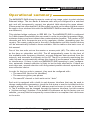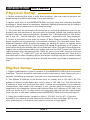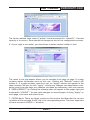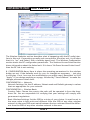
1
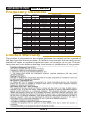
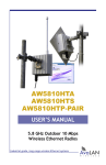
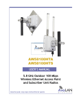
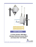
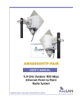
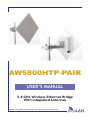
AW5800HTP-PAIR USER’S MANUAL 5.8 GHz Wireless Ethernet Bridge With Integrated Antennas Industrial-grade, long-range wireless Ethernet systems AvaLAN W I R E L E S S AW5800HTP-PAIR User’s Manual Thank you for your purchase of the AW5800HTP-PAIR point-to-point wireless Ethernet bridge. The AW5800HTP-PAIR includes: • (2) Integrated Radio & Antenna Units • (2) 120 VAC to 18 VDC power adapters • (2) AW-POE Power Over Ethernet Injectors If you have any questions when configuring your AvaLAN system, the best place to get answers is to visit www.avalanwireless.com. You will also find the latest updates there. If more assistance is needed, send email to [email protected]. To speak to a live technician, please call technical support at the number below during normal business hours. © 2009 by AvaLAN Wireless Systems Inc. All rights reserved. Revision 090727.0 125A Castle Drive Madison, AL 35758 Sales: (866) 533-6216 Technical Support: (650) 384-0000 Customer Service: (650) 641-3011 Fax: (650) 249-3591 Technical support (650) 384-0000 PAGE 2 www.avalanwireless.com User’s Manual AW5800HTP-PAIR Operational summary The AW5800HTP-PAIR allows the user to create a long-range, point-to-point wireless Ethernet bridge. The two Radio & Antenna units are pre-configured as a matched pair and will transparently connect two physical LANs sharing the same subnet. (Please note that other AvaLAN 5.8 GHz radios can exist on the same LAN but cannot be used to form wireless links with the AW5800HTP-PAIR because the RF parameters are different.) This wireless bridge conforms to IEEE 802.11a. The AW5800HTP-PAIR is configured for 5 MHz channel bandwidth (the narrowest) in order to provide the greatest range, minimum latency and most robust data communication possible. The number of RF channels and their frequencies are set by regulatory bodies, depending upon the country. The country may be set in the unit’s configuration and the channel choices will be automatically limited to those available. See the table on the back cover of this manual. One of the two units acts as the master or access point (AP). The other unit acts as the slave or subscriber unit (SU). The AP automatically scans for the best of the available radio frequency channels, encrypts Ethernet data received from the network, and transmits it wirelessly to the SU. The AP is constantly monitoring the radio link and can automatically change the channel if performance is degraded due to interference. If there is just one AW5800HTP-PAIR operating in your configuration, automatic channel selection is likely to be the best alternative. If there are more than one, manual selection with the greatest possible channel separation is a more effective choice. In order for the two units to connect, they must be configured with: • The same SSID (Service Set Identifier) • The same encryption pass phrase • The same RF channel or both units set to “Auto” Each unit is equipped with a built-in web browser interface that may be used to change configuration parameters, check the link status or use the included tools for antenna aiming, etc. Each unit’s IP address must be known in order to browse to it. The IP address may be changed through the browser interface, but this creates a “chicken and egg” problem. If the default IP addresses set by the factory are not suitable, you may need to temporarily connect them to a computer that can browse to the units. Technical support (650) 384-0000 PAGE 3 www.avalanwireless.com AW5800HTP-PAIR User’s Manual Physical Setup 1. Before mounting the units in their final locations, you may want to perform the digital setup procedure described in the next section. 2. Mount each unit of the AW5800HTP-PAIR securely using the mounting brackets provided or other means as necessary. Maximize lightning resistance by providing a strong DC ground connection to the metal housing. 3. The units may be mounted with horizontal or vertical polarization and it is important that the antennas of the two units be pointed toward one another and be oriented with the same polarization. Because the 3 dB beamwidth of the antennas is just 10°, careful aiming is very important − especially over long distances. 4. Power is provided to the units by means of their Ethernet cables, allowing the power supplies to be located at a convenient locations. The included power-overEthernet injectors (POE) provide the means for adding DC power to unused wires in the cable. Decide where to place each POE based on proximity to AC power at some point along the desired path of the Ethernet cable. Plug each included power supply into an appropriate electrical outlet and into the POE. Connect an Ethernet cable between your network and the “DATA IN” port on the POE. Connect a second cable from the “P + DATA OUT” port on the POE and the AvaLAN unit. Each unit is provided with a cable clamping device that allows an RJ45 plug on the cable to pass through it and can be tightened down around the cable to provide a weatherproof seal. Digital Setup 1. Digital configuration is done by means of the AW5800HTP-PAIR’s built in browser interface. The unit should be powered on and connected at least temporarily to a network containing a computer that can run a conventional web browser. 2. The default IP address of the Access Point or master unit is 192.168.1.66. The default IP address of the Subscriber Unit or slave is 192.168.1.67. You will find the IP address of each unit on its product label. If these are acceptable in your network configuration, they needn’t be changed. If not, you will need to connect each unit temporarily to a computer whose wired LAN port has an IP address of 192.168.1.xxx (with xxx not 66 or 67). In other words, the computer that will run the web browser must connect to the same subnet as each AW5800HTP-PAIR unit being configured. 3. Using your web browser, connect to http://192.168.1.66 (or 67). If you are successful, you should see the login screen shown on the next page. By the way, after some period of inactivity, you may be required to login again. Technical support (650) 384-0000 PAGE 4 www.avalanwireless.com User’s Manual AW5800HTP-PAIR The factory default login name is “admin” and the password is “admin01”. If access security is a concern, these should be changed as part of the configuration process. 4. If your login is successful, you should see a status window similar to this: The menu in the top banner allows you to navigate from page to page. If a page contains status information such as this one, clicking the “Refresh” button will update it. If a page contains controls to set, an “Apply” button will appear in the same location. Be sure to click “Apply” to keep any changes you make before navigating away from the page. Any changes you make are temporary until you execute a “SAVE & REBOOT” by clicking the message that will appear in the upper right just underneath “LOGOUT.” You can make changes on several pages, clicking “Apply” on each page, then save and reboot once. 7. STATUS Menu: There are three screens in this section that describe the current condition of the unit and the RF link to its corresponding mate. The most important of these screens is STATUS >> Wireless: Technical support (650) 384-0000 PAGE 5 www.avalanwireless.com AW5800HTP-PAIR User’s Manual The Wireless Statistics section describes what is happening with the RF radio interface in this unit. If operating normally and connected to the other unit, it will show that it is “up” and linked, with a healthy signal level. The Wireless Configuration section shows the RF configuration parameters. The Stations/Access-Points section shows information about the linked unit. If it shows “No Peers/Access-Points found” then the RF link is not working. 8. CONFIGURATION Menu: Here is where the operating parameters for the wireless bridge are set. If the defaults work for you, no changes are necessary — just plug in and play. If not, here are the modifications you might need. Remember to click “Apply” if you change anything on a page, followed by “Save & Reboot” to make the changes permanent when done. CONFIGURATION >> Network: Network Settings: Set the IP address, Subnet mask and Default gateway to values that are appropriate for your network. CONFIGURATION >> Wireless Basic: Country Code: Choose the country the units will be operated in from the dropdown list. You are responsible for verifying that your settings will comply with government regulations. Basic Wireless Settings: Set the SSID to a string of your choice. It must be set to the same value in both units and different from the SSID of any other wireless network in the area.SSID must match between the two units and should be different from the SSID of any other wireless network in the area. Technical support (650) 384-0000 PAGE 6 www.avalanwireless.com User’s Manual AW5800HTP-PAIR Channel is a drop-down list that allows fixed or automatic selection of the RF channel from the available choices in your country. This choice must be made alike in both units. CONFIGURATION >> Wireless Security: You should choose a Passphrase of your own. The Authentication method and Passphrase must be set the same in both units. CONFIGURATION >> Wireless Advanced: The radio used in each unit has a +10 dBm offset. For example, to set a transmit power of 24 dBm, move the slider or enter 14 in the box. Depending on the operating environment for your wireless bridge, you may wish to set a value lower than the default maximum of 18, implying +28 dBm or about 600 mW transmitted power. 9. SYSTEM Menu: There is only one item in this section that needs attention. You may need to use other items in this menu, but do so only when instructed by AvaLAN Technical Support. SYSTEM >> Account: Administrative Account: Choose a login and password for this browser interface (and make sure you don’t forget it). 10. TOOLS Menu: There are three tools accessable from this menu that may be useful for establishing your wireless connection or troubleshooting problems. TOOLS >> Site Survey: Clicking the “Scan” button on this screen initiates a survey of wireless devices whose signals are received by this unit. All available RF channels are scanned. You should see the Master unit of the pair if scanning from the Slave, but not vice versa. If you see another network, you will probably want to manually select a different channel to avoid loss of performance. TOOLS >> Antenna Alignment: You will need to have at least a minimum RF connection to use this tool, but it can help you to orient the antennas for the largest signal. Click “Start” and the bar graph will grow by one bar per second until you stop. The vertical scale is logarithmic (dB) and the bars should get taller or shorter with antenna adjustments. Click “Stop” when you have completed aligning your antennas. TOOLS >> Traffic Generator: This tool generates TCP or UDP traffic over the RF link and measures the throughput. Configure one of the two units as a Server and the other as a Client. Clicking “Start” at both ends causes the rapid exchange of traffic and accumulates throughput statistics. Be sure to stop the Server when finished using this tool or the link performance will be degraded. Technical support (650) 384-0000 PAGE 7 www.avalanwireless.com AW5800HTP-PAIR User’s Manual Frequency Channels Frequency Band Lower Band (FCC specifies Indoor use, ≤24 dBm) Middle Band (Indoor or outdoor use, ≤27 dBm) H Band Upper Band (FCC specifies Outdoor use, ≤30 dBm) ISM Band Channel Number 34 36 38 40 42 44 46 48 52 56 60 64 100 104 108 112 116 120 124 128 132 136 140 149 153 157 161 165 Frequency MHz 5170 5180 5190 5200 5210 5220 5230 5240 5260 5280 5300 5320 5500 5520 5540 5560 5580 5600 5620 5640 5660 5680 5700 5745 5765 5785 5805 5825 FCC and Americas Limited Warranty Indoor Only Indoor Only Indoor Only Indoor Only OK OK OK OK Outdoor Only Outdoor Only Outdoor Only Outdoor Only OK Regulatory Domain Europe - EMEA Japan OK OK OK OK OK OK OK OK OK OK OK OK OK OK OK OK OK OK OK OK OK OK OK Rest of World OK OK OK OK OK OK OK OK OK This product is warranted to the original purchaser for normal use for a period of 360 days from the date of purchase. If a defect covered under this warranty occurs, AvaLAN will repair or replace the defective part, at its option, at no cost. This warranty does not cover defects resulting from misuse or modification of the product. Technical support (650) 384-0000 PAGE 8 www.avalanwireless.com