1
Application Note
ZMOTIONTM Detection Module
Application Walkthrough
AN030704-1110
Abstract
This application note describes in detail the application code associated with the ZMOTION Detection Module
and how it can be used for detection and control applications. The ZMOTION Detection Module can be used
either in Hardware Mode or Serial Mode. In the Hardware Mode, you use the hardware circuit selection for
sensitivity adjustments, delay time settings, ambient light settings, and Sleep Mode. In the Serial Mode, you
can use the UART interface to fine-tune the ZMOTION Detection Module with advanced configuration
settings.
Note: The application code (AN0307-SC01) associated with this application note has been tested with
ZDS II—Z8 Encore! version 4.11.0.
ZMOTION Overview
Zilog’s ZMOTION Detection Module is a complete, compact, and easy to interface solution for motion
detection and direction. It is designed using advanced passive infrared technology and Zilog’s Z8FS04 Motion
Detection MCU with a powerful embedded software engine that delivers high-performance motion detection.
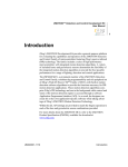
Figure 1 on page 2 shows the location of the pins on the ZMOTION Detection Module. Table 1 on page 2
describes the pin functions.
Copyright ©2010 by Zilog®, Inc. All rights reserved.
www.zilog.com
ZMOTIONTM Detection Module Application Walkthrough
Figure 1. ZMOTION Detection Module Pin Diagram
Operation Modes
There are two operation modes: Hardware Interface Mode and Serial Interface Mode.
In the Hardware Interface Mode, you can make the following adjustments:
• Use the hardware interface pins for basic configuration.
• Adjust the motion sensitivity with the voltage on the SNS pin.
• Adjust the time delay (Output Active Time) with the voltage on the DLY pin
• Set the optional ambient light input.
• Use the Sleep Mode to reduce power consumption.
In the Serial Interface Mode, you can use the serial interface (Rxd and Txd) for advanced configuration:
• 9600 baud rate
• No parity
• 8 data bits
• 1 stop bit
• No flow control
The /MD, LG, and SLP pins remain functional.
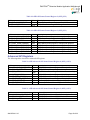
Table 1. ZMOTION Detection Module Pin Description
Pin No.
1
2
3
4
Signal Name
GND
VDD
RXD/DLY
TXD/SNS
AN030704-1110
Hardware Interface
Mode
Ground
Supply Voltage
DLY-Delay (analog
input)
SNS Sensitivity
(analog input)
Serial Interface Mode
Ground
Supply Voltage
RXD Receive Data (digital
input)
TXD Transmit Data (digital
input)
Description
—
—
—
Mode select during Reset
Page 2 of 32
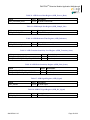
ZMOTIONTM Detection Module Application Walkthrough
Pin No.
5
Signal Name
/MD/RST
6
LG
7
/SLP/DBG
8
GND
Hardware Interface
Mode
Motion Detect (digital
output)
Light Gate (analog
input)
/SLP Sleep (digital
input)
Ground
Serial Interface Mode
Configurable: /RST Reset
(digital input)
/MD Motion Detect (digital
input)
Light Gate
(analog input)
/SLP Sleep
(digital input)
Ground
Description
Default is /RST (Reset) in
Serial Interface Mode
If unused, connect to Vdd.
DBG is used for
programming and debug.
—
Hardware Interface Mode Description
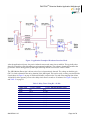
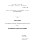
Figure 2 shows a typical example of how to connect the ZMOTION Detection Module using Hardware
Interface Mode. This mode of operation is selected when a voltage between 0 V and 1.8 V is presented to the
SNS pin during power ON (or after a reset caused by Vbo). When the Hardware Interface Mode has been
established, this pin becomes the Sensitivity input and accepts a voltage between 0 V and 1.8 V as reference
for motion detection sensitivity level.
•
•
0 V = Highest Sensitivity
1.8 V = Lowest Sensitivity
In Figure 2, R2 and R4 form a simple potentiometer resistor divider to ensure that the Hardware Mode is
entered upon reset and to control sensitivity levels.
AN030704-1110
Page 3 of 32
ZMOTIONTM Detection Module Application Walkthrough
Figure 2. Application Example of Hardware Interface Mode
After the application of power, the passive infrared sensor needs some time to stabilize. This typically takes
about 20 seconds but varies depending on environmental conditions. The software dynamically monitors the
pyroelectric sensor during power-up and begins detecting motion as soon as the sensor is stable.
The /MD (Motion Detect) pin is driven active (Low) when motion is detected. The voltage on the delay pin
(DLY) is used to determine the active duration of the /MD signal. This can be easily set using a resistor divider
circuit shown in Figure 2 on page 4. With an 82-kΩ (R1) resistor tied to Vcc and values ranging from 0 Ω to
100 kΩ (R3) tied to ground, you can select delay times from 2 seconds to 15 minutes. See Figure 2 on page 4
and Table 15 on page 21.
Table 2. Delay Times Using R1 = 82 KΩ
Delay Time
2 sec
5 sec
10 sec
30 sec
1 min
2 min
3 min
5 min
10 min
15 min
AN030704-1110
R_DLY Voltage
0V
0.2 V
0.4 V
0.6 V
0.8 V
1.0 V
1.2 V
1.4 V
1.6 V
1.8 V
R_DLY Standard Resistor Value
0Ω
5.1 kΩ
11 kΩ
18 kΩ
24 kΩ
33.2 kΩ
43 kΩ
56 kΩ
68 kΩ
91 kΩ
Page 4 of 32
ZMOTIONTM Detection Module Application Walkthrough
The Light Gate (LG) signal acts as a disable (gate) for the /MD output signal. In a typical application, this
signal is a representation of the ambient light in the environment. If there is light detected, the /MD signal does
not activate even in the presence of motion.
Serial Interface Mode Commands
The Serial Interface Mode operates as a host-client relationship where the ZMOTION Detection Module is the
client. Commands are sent from the host, and the module responds with the requested information or
confirmation. The only exception is when the module is configured for “/MD Unsolicited” operation. Under
this condition, it will send motion-detected information without first receiving a command from the host.
All the serial commands sent to the ZMOTION Detection Module are in ASCII characters format, but the data
sent to and from the module can be ASCII or decimal.
There are three types of commands accepted by the module:
• Read commands
• Write commands
• Confirmation commands
Read Command Structure
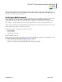
Read commands are used to request information from the module. Read commands are sent from the host, and
the module responds with the requested data. See Figure 3 on page 6.
• All read commands are initiated by single lower-case letters.
• When received, the device will return the applicable value as described in
AN030704-1110
Page 5 of 32
ZMOTIONTM Detection Module Application Walkthrough
Table 16 on page 22.
Figure 3. Read Command Structure
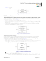
Write Command Structure
Write commands are used to update configuration of the module. The command is sent from the host, and the
module responds with the current value as an acknowledgment. Then the host sends the new data, and the
module responds with an 'ACK'. See Figure 4.
• All write commands are initiated by single upper-case letters.
• When a write command is received, the device returns the current value and expects an appropriate singlebyte data value.
• When the data value is received, the device returns an 'ACK'. If no data is received after the inactivity
timeout of 2.5 seconds, the device returns a 'NACK'.
Figure 4. Write Command Structure
Confirmed Command Structure
Certain commands require a specific sequence of characters to be sent in order to help prevent accidental
initiation. These commands require a 4-character confirmation sequence. When a command requiring
confirmation is received, the device returns an 'ACK' . See Figure 5.
• If the sequence is correct, the device returns an 'ACK' and executes the command.
• If the sequence is incorrect, or there is an inactivity delay of more than 2.5 seconds between any characters
of the sequence, the device immediately sends a 'NACK' and does not execute the command.
Figure 5. Confirmed Command Structure
Notes: 1. ACK = 0x06 (ASCII ACK character).
2. NACK = 0x15 (ASCII NACK character). The ZMOTION will respond with a 'NACK' on all
AN030704-1110
Page 6 of 32
ZMOTIONTM Detection Module Application Walkthrough
unrecognized commands or when a command requires data (that is, Write, Clear, and
Confirmation types) but does not receive the required data within the inactivity timeout period.
Software Overview
The application code in the ZMOTION Detection Module first executes an initialization procedure, which is
discussed in the “Setting the Operational Mode” section on page 8. When the module is enabled, the ADC
interrupt runs in the background (see Figure 6). Every ADC conversion generates an interrupt and the
ZMOTION engine performs its functions during this time (see Figure 6). The user application code runs in the
foreground and monitors the status through the API and performs any other functions required for the
application, which is discussed in the “Main Application Loop” section on page 9.
Figure 6. ADC Interrrupt for ZMOTION Detection
One-Second Timer Tick
The ZMOTION engine requires a 1-second time base to perform various housekeeping operations (see Figure
7 on page 8). This is handled in the application by the timer interrupt. The Timer0 Interrupt is configured for
100 ms. The application code counts 10 of these interrupts and sets the Engine Timer Tick bit in ePIR_SC1.
AN030704-1110
Page 7 of 32
ZMOTIONTM Detection Module Application Walkthrough
1 Second
Timer Interrupt
Set bit 7 of ePIR_SC1
(Engine Timer Tick)
One
Second
Timer Tick
Return
Figure 7. One-Second Engine Timer Tick
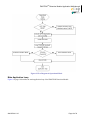
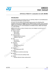
Setting the Operational Mode
The mode of operation (HW or Serial mode) can be selected using the TXD/SNS pin during the power ON or
when exiting the Sleep Mode. The following explains the program in the operational mode (see Figure 8 on
page 9):
1.
The program starts by initializing all of the needed peripherals.
2.
Check the Stop Mode Recovery SMR reset. If there is NO SMR reset, then the sensitivity level is
set to default and the ePIR status register is initialized.
3.
The ePIR_ENABLE register is set to EPIR_ENABLE_PATTERN, so the engine can be enabled.
4.
The EPIR_INIT macro is executed to initialize the ePIR engine.
5.
Initialize Timer0 and set to 100-ms interrupt.
6.
Check analog channel 0 (ANA0), which is connected to PIN4 or TXD/SNS if the analog level
exceeds the threshold or not. This is repeated 10 times to ensure a stable reading. If the TXD/SNS
pin is above the threshold, then the cCmdState is set to 1; else, it is set to 0. This is done to
stabilize the ePIR engine.
7.
Next, the mode of operation is determined with the value of the cCmdState. If the cCmdState is 1,
then the Mode of Operation is Serial Interface, and if the cCmdState is 0, then the Mode of
Operation is Hardware Interface.
8.
Finally, the mode of operation is set, and cCmdState is set to IDLE state; it then proceeds to the
main application loop.
AN030704-1110
Page 8 of 32
ZMOTIONTM Detection Module Application Walkthrough
Figure 8. Flow Diagram of Operational Mode
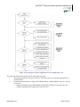
Main Application Loop
Figure 9 on page 10 describes the main application loop of the ZMOTION Detection Module.
AN030704-1110
Page 9 of 32
ZMOTIONTM Detection Module Application Walkthrough
Figure 9. Flow Diagram of Main Application Loop of Application Code
The following describes the operation of the main application loop:
1.
The program checks the Sleep pin if it is low. If the Sleep pin is low, then the program enters to
the Sleep Mode.
2.
Next the program checks the content of the cModule Status1 (cModuleStatus1) flag. See Table 20
on page 24.
• If the Serial Mode Register (SER_MODE_ENABLED) is HIGH, several select cases are
available depending on the inputs of the select case. See
AN030704-1110
Page 10 of 32
ZMOTIONTM Detection Module Application Walkthrough
Table 17 on page 23. The contents of the cModuleStatus1 flag are evaluated and updated.
If the Sleep Mode Request (MOD_SLEEP_REQ) is HIGH, then the MCU Sleep Flag will be
on, and the MCU will go to sleep. This is to reduce the power consumption of the MCU
especially for battery-powered devices.
The program checks the state of the cModule Status2 (cModuleStatus2) flag. See Table 21 on page
24.
• If the ADC current channel scan (SCAN_SENS_POT) is HIGH and the conversion for Sense
potentiometer is complete, then the program gets the latest Sense value from the
potentiometer.
• If the Scan delay pot (SCAN_DELAY_POT) is HIGH and the conversion for Delay
potentiometer is complete, then the program gets the latest Delay setting from the
potentiometer
• If the Scan Light Gate (SCAN_LIGHT_GATE) is HIGH and the conversion for the Light
Gate is complete, then the program gets the latest ambient light level for light comparison.
• If the Scan Request (SCAN_REQUEST_NEW) new is high, then the program will request
new ADC channel conversion.
Finally, the program checks again the status of the cModule Status1 (cModuleStatus1) flag. See
Table 20 on page 24.
• If the Mode Pir Stable (MOD_PIR_STABLE) is LOW, then the program checks the PIR
sensor stability after power up.
• If the Mode Pir Stable (MOD_PIR_STABLE) is HIGH, the engine will indicate an alarm and
checks for motion detected and updates the output.
•
3.
4.
Sleep Mode in Hardware Interface Mode
Sleep signal can be used to put the device into a low-power mode. Using this feature will allow a shorter PIR
stabilization time.
If the Sleep (/SLP) input signal is driven LOW, the device enters into a low-power Sleep Mode. It can be
awakened by either deactivating the /SLP signal (driving the signal HIGH) or sending a character over the
serial interface; the received character is received and processed.
Serial Interface Mode (Software Interface Mode)
The Serial Interface Mode is responsible for handling serial command input and processing. See Table 3.
Table 3. Command State (cCmdState)
Command State (cCmdState)
Idle State
Real Time State
Suspend Status State
Serial Interface Mode State
Sensitivity Change State
AN030704-1110
Description
This state puts the ZMOTION into standby mode
This state puts the program in real-time mode. This state is enabled if the
received command is “Y” and disabled if the received command is “N”.
This state temporarily enables or disables the motion detection of the program.
This state is enabled if the received command is “Y” and disabled when the
receive command is “N”.
This state let the user change the mode of sending the data format of the
ZMOTION to either ASCII or Decimal. The ASCII mode is enabled if the
command received is “A” and Decimal Mode if the command received is “D”.
This state changes the sensitivity of the ePIR engine to the target motion.
Sensitivity is higher with a lower number value. 0x00 being the most sensitive
and 0xFF being the least sensitive.
Page 11 of 32
ZMOTIONTM Detection Module Application Walkthrough
Command State (cCmdState)
Sleep Duration State
Delay Change State
Light Threshold Change
State
MD Output Change State
Configuration Change
Direction Change State
Dual Direction Change State
Hyper-sense Change State
Ping Write Request State
Frequency Response State
Range Control State
Reset Mode State
Sleep Mode State
Description
This state changes the time duration of Sleep Mode.
This state changes the time delay of changing the state from one state to
another.
This state is used to control and monitor the signal associated with the Light
Gate pin.
This state indicates how the ePIR engine detected the last motion-detected
event. When the ZMOTION sets the Motion Detected bit in ePIRStatus0, it
also sets this bit according to which detection engine registered the event.
This state is used to configure the motion detection. If the received command
is ‘R’, then it is requesting for a Reset. If the receive command is ‘M’, then it is
requesting for make motion detection.
This state is used to configure the direction of the motion to positive, negative,
or disabled. Positive movement is requested when a “+” is received, negative
movement is requested when a “-” is received, and disabled motion detection
is requested when “A” is received.
This state determines if the engine should accept signals from one or two ePIR
sensor. If configured as single operation then only one sensor is used which is
connected to ANA2. If it is configured as dual operation then ZMOTION will
scan two sensors simultaneously with the second sensor connected to ANA3.
This state changes the sensitivity of the ZMOTION. If this state is enabled, the
engine considers smaller signal changes as valid motion events. This
significantly increases sensitivity at the cost of more potential false motion
detections.
This state is used to clear and temporarily save the received command.
This state determines the frequency response of the motion detection system.
Higher values allow lower frequencies to be accepted by the ePIR engine.
Lower values cause the engine to ignore targets that generate lower
frequencies.
This state determines the relative range of motion detection. Larger values
decrease the range of detection.
This state uses the watch-dog timer to have system reset.
This state puts the program in Sleep Mode. This state uses the watch-dog
timer to have system reset that wakes up MCU.
Sleep Mode Request in Serial and Hardware Interface Mode
The program enters Sleep Mode request if MOD_SLEEP_REQ in cModuleStatus1 register is enabled and
sleeps for the given time duration depending on the value of the set sleep duration.
Sensitivity Setting from Potentiometer (Hardware Interface Mode)
Get the latest Sense setting from the Pot. The program gets the latest sense from the potentiometer if the
SCAN_SENS_POT is enabled in cModuleStatus2 register and the SC3_ANA0_SCAN_REQUEST is disabled.
Then the ePIR_sensitivity is updated.
Delay Setting from Potentiometer (Hardware Interface Mode)
Get the latest Delay setting from the Pot. The program checks if the SCAN_DELAY_POT is enabled in
cModuleStatus2 register and then updates the cDelayTime.
AN030704-1110
Page 12 of 32
ZMOTIONTM Detection Module Application Walkthrough
Ambient Light Level for Gate comparison (Hardware Interface Mode)
Get the latest Ambient light level for Light Gate comparison. The program checks if the
SCAN_LIGHT_GATE is enabled in cModuleStatus2 register and the updates the value of cLGAmbient.
ADC Conversion and Request Next Channel Conversion (Hardware Interface Mode)
Request new ADC channel conversion. The program checks if the SCAN_REQUEST_NEW is enabled in
cModuleStatus2 register and then the cModuleStatus2 register is updated.
Sensor Stability
Check for PIR sensor stability. The program checks the stability of the system by verifying if the
MOD_PIR_STABLE is enabled in cModuleStatus1 register after power up.
Motion Detection
Check for motion detected and update the output on time as needed. The program checks if motion is detected
by checking if the SCO_MOTION_DETECTED is enabled in ePIR_SCO register then send it once it is
needed.
References
The following documents are associated with ZMOTIONTM Detection Module and are available on
www.zilog.com:
• ePIR Motion Detection Zdots Single Board Computer Product Brief (PB0223)
• ePIR Motion Detection Zdots SBC Product Specification (PS0284)
• ZMOTION Detection Module Evaluation Kit User Manual (UM0223)
• ZMOTION Detection Module Development Kit Quick Start Guide (QS0073)
• Motion Detection and Control with ePIR Zdots Single Board Computer Cut Sheet (CS0005)
• ZMOTION—A New PIR Motion Detection Architecture White Paper (WP0017)
• Power Management and Customer Sensing with Zilog's ZMOTION Detection Module Application Note
(AN0301)
• ZMOTION Detection and Control Family Featuring ePIR Technology Product Specification (PS0285)
• ZMOTION Lens and Pyroelectric Sensor Product Specification (PS0286)
• Z8 Encore! XP F0822 Series Product Specification (PS0225)
• Z8 Encore! XP F082A Series Product Specification (PS0228)
AN030704-1110
Page 13 of 32
ZMOTIONTM Detection Module Application Walkthrough
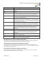
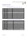
Appendix A—Pre-Build Setup
This appendix lists the settings and resources you need for your build.
Use the following Compiler and Linker settings to prepare for your build:
ZDS Version
CPU Family
CPU
Limit Optimizations for Easier Debugging
Memory Model
Frames
Parameter Passing
Use Register Variables
Generate printf Inline
Bit-Field Packing
Place CONST Variables in ROM
Disable ANSI Promotions
Address Space
ZDSII Encore! 4.11.0
Z8Encore_XP_F082A_8Pin_Series
Z8F042AXB
unchecked
Small
Static
Memory
Aggressive
unchecked
Backward Compatible
unchecked
unchecked
Default settings + Use PRAM checked
Table 4 lists the resources used by the build.
Table 4. Resources Used
Clock Source
Internal clock source, 5.52960 MHz
Peripherals
TMR0
UART0
WDT
PA0 or Debug, PA1,
PA2 or RESET and PA4
ADC – ANA2 to ANA3
AN030704-1110
One-second timer used in low-power mode
RS232 interface
Software reset and watch-dog function
Used for input and output pins.
These are used for the ePIR output for motion detection.
Page 14 of 32
ZMOTIONTM Detection Module Application Walkthrough
Appendix B—Library and Software Tool Files
This appendix describes the standard project files and external dependencies.
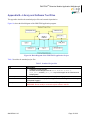
Figure 10 shows the block diagram of the ZMOTION application program.
Figure 10. Block Diagram of the ZMOTION Application Project
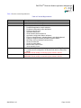
Table 5 describes the standard project files.
Table 5. Standard Project files
File
main.c
startupePIR.asm
Zsldevinit.asm
ePIR_API.c
AN030704-1110
Description
• Handles the main program.
• Includes several libraries such as eZ8.h, defines.h, main.h,
ePIR_API.h, and API_INIT_06.h to provide support to the functions and
subprograms.
Used to set the Linker address spaces in project settings.
Used to set the ZSL in the project settings to include the Zilog Standard Library
(Peripheral Support).
Contains the ePIR standard and advanced API registers
WARNING: Do not modify or remove the given values in this file.
Page 15 of 32
ZMOTIONTM Detection Module Application Walkthrough
Table 6 lists the external dependencies.
Table 6. External Dependencies
File
eZ8.h
defines.h
main.h
API_INIT_06.h
ePIR_API.h
AN030704-1110
Description
Contains the standard Z8 library.
Define the names for control register access.
Contains project header that includes:
• Predefined application compile switches
• Peripheral configuration macro definitions
• Reserve interrupt vector
• Application definitions
• Serial interface Macro definitions
• Application configuration Macro definitions
• Flags for cModuleStatus1, cModuleStatus2, and cModuleStatus3
• Delay pot voltage thresholds (Hardware Interface Mode)
• MD Delay values (Hardware Interface Mode)
• Serial Command List
• Serial Command States
• Motion Alarm output macro
• Inline assembly macro
• Handles the functions and subprograms declared in ePIR_API.c.
• Contains the API configuration for Normal Scan and Low Scan Rate
Mode.
WARNING: Do not modify or remove the given values in this file.
Defines the standard and advanced API interface.
WARNING: Do not modify or remove the given values in this file.
Page 16 of 32
ZMOTIONTM Detection Module Application Walkthrough
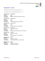
Appendix C—main.c
This appendix describes the function prototypes in main.c.
The following is a list of the function prototypes in main.c:
Function Name
Returns
Parameters
Description
makeMDReset
-none-noneRoutine for making the /MD pin a reset input
Function Name
Returns
Parameters
Description
makeMDMotion
-none-noneConfigure /MD pin as Motion Detected.
Function Name
Returns
Parameters
Description
checkCommand
-none-noneCheck the newly received command.
Function Name
Returns
Parameters
Description
SerialReceive
unsigned char intData
-noneCharacter received through serial communication
Function Name
Returns
Parameters
Description
cSerialRX
unsigned char rxData
-noneCopy the character in the serial buffer
Function Name
Returns
Parameters
Description
cSerialTX
-noneunsigned char rxData
Transmit the character in the serial buffer
Function Name
Returns
Parameters
Description
TxDirect
-noneunsigned char rxData
Transmit byte via UART0
AN030704-1110
Page 17 of 32
ZMOTIONTM Detection Module Application Walkthrough
The following is a list of the interrupt function prototypes in main.c:
Function Name
Returns
Parameters
Description
interrupt isrADC_EOC
-none-noneADC for End of Character (EOC) interrupt
Function Name
Returns
Parameters
Description
interrupt isrTimer0
-none-noneTIMER0 timeout interrupt
Function Name
Returns
Parameters
Description
interrupt isrRX0
-none-noneUART0 RX interrupt
AN030704-1110
Page 18 of 32
ZMOTIONTM Detection Module Application Walkthrough
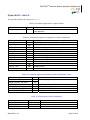
Appendix D—ePIR_API.c
This appendix describes the contents of ePIR_API.c.
Table 7. Register Address of Standard API Interface (x100 to 0x10F)
Address
100h
101h
102h
103h
104h
105h
106h
107h
108h
109h
10Ah
10Ch
10Dh
10Eh
10Fh
Size
1 byte
1 byte
1 byte
1 byte
1 byte
1 byte
1 byte
1 byte
1 byte
1 byte
2bytes
1 byte
1 byte
1 byte
1 byte
Name
ePIR_Enable
ePIR_Sensitivity
ePIR_SC0
ePIR_SC1
ePIR_SC2
ePIR_SC1
ePIR_Reserved_106
ePIR_Reserved_107
ePIR_Reserved_108
ePIR_Reserved_109
ePIR_ADC_Result
ePIR_Version
ePIR_Reserved_10D
ePIR_Reserved_10E
ePIR_Reserved_10F
Description
ePIR API Enable Register
ePIR API Sensitivity Register
ePIR API Status and Control Reg. 0
ePIR API Status and Control Reg. 1
ePIR API Status and Control Reg. 2
ePIR API Status and Control Reg. 3
Reserve Standard API Register
Reserve Standard API Register
Reserve Standard API Register
Reserve Standard API Register
ePIR ADC result Register
ePIR Engine S/W Version Register
Reserve Standard API Register
Reserve Standard API Register
Reserve Standard API Register
Table 8. Register Address of Advanced API Interface (0xF0 to 0xFF)
Address
F0h
F1h
F2h
F3h
F5h
F6h
F7h
F8h
F9h
FAh
FCh
FEh
FFh
Size
1 byte
1 byte
1 byte
2bytes
1 byte
1 byte
1 byte
1 byte
1 byte
2bytes
2bytes
1 byte
1 byte
AN030704-1110
Name
ePIR_ASC0
ePIR_Reserved_F1
ePIR_ASC2
ePIR_Process_Rate
ePIR_Sample_Size
ePIR_Debounce
ePIR_Debounce_Batch
ePIR_Transient_Sense
ePIR_Noise_Sense
ePIR_Signal
ePIR_Signal_DC
ePIR_Reserved_FE
ePIR_Reserved_FF
Description
Advanced API Status\Control Reg.0
Reserved Advanced API Register
Advanced API Status\Control Reg.2
ePIR Process Rate Register
ePIR Sample Size Register
ePIR Debounce Time Register
ePIR Debounce Batch Size Register
ePIR Transient Sensitivity Reg.
ePIR Noise Sensitivity Register
ePIR PIR Signal Register
ePIR PIR Signal DC Level Register
Reserved Advanced API Register
Reserved Advanced API Register
Page 19 of 32
ZMOTIONTM Detection Module Application Walkthrough
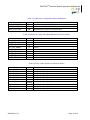
Appendix E—main.h
This appendix describes the contents of main.h.
Table 9. Predefined Application Compile Switches
Define
ZDOT_APP_ID
Value
BEh
Description
Identification for user to uniquely identify each released version
of the application
Table 10. Predefined Peripheral Configuration to Macro Definitions
Define
U0_BAUD_HIGH
U0_BAUD_LOW
U0CTL0_VAL
U0CTL1_VAL
T0RH_VAL
T0RL_VAL
T0CTL0_VAL
T0CTL1_VAL
WDTU_VAL
WDTH_VAL
WDTL_VAL
OSCCTL_VAL
PWRCTL0_VAL
Value
00h
24h
C0h
00h
87h
02h
00h
E1h
00h
27h
10h
A0h
8Ah
Description
UART 0 BRG high setting for 9600 Baud with IPO
UART 0 BRG low setting for 9600 Baud with IPO
UART 0 Control Register 0 value
UART 0 Control Register 1 value
Timer 0 reload value high when set for 5.5MHz standard clock
Timer 0 reload value low when set for 5.5MHz standard clock
Timer 0 Control 0 Register value
Timer 0 Control 1 Register value
WDT Upper byte, ~1000 ms
WDT High byte, ~1000 ms
WDT Lower byte, ~1000 ms
Oscillator control
Power control 0 register value
Table 11. Predefined Application Definitions with Initial Default Values
Define
SENSE_ADJUST_HW_MIN
SENSE_ADJUST_HW_MAX
LG_THRESHOLD
LOW_FREQUENCY_RESPONSE
HIGH_FREQUENCY_RESPONSE
SER_IDLE_TIMEOUT
Value
10h
FFh
64h
28h
00h
19h
Description
Sensitivity adjustment, lower is more sensitive
Light Gate threshold POR Default value
Default Frequency Response value
High Frequency Response value
Serial Interface Mode Inactivity timeout (x 100ms)
Table 12. Serial Interface Macro Definitions
Define
SER_ACK
SER_NACK
SER_AWAKE
AN030704-1110
Function
TxDirect(0x06)
TxDirect(0x15)
TxDirect(0x16)
Description
Serial Acknowledge
Serial Not Acknowledge
Serial Awake
Page 20 of 32
ZMOTIONTM Detection Module Application Walkthrough
Table 13. Application Configuration Macro Definitions
Define
MOD_STAT1_DEF
MOD_STAT2_DEF
MOD_STAT3_DEF
Value
08h
00h
08h
Description
cModuleStatus1 register POR Default value
cModuleStatus2 register POR Default value
cModuleStatus3 register POR Default value
Table 14. Delay Pot Voltage Threshold (Hardware Interface Mode)
Define
DLY_POT_000MV
DLY_POT_200MV
DLY_POT_400MV
DLY_POT_600MV
DLY_POT_800MV
DLY_POT_1000MV
DLY_POT_1200MV
DLY_POT_1400MV
DLY_POT_1600MV
Value
10
31
51
71
92
112
132
153
173
Description
0 mV
200 mV
400 mV
600 mV
800 mV
1000 mV
1200 mV
1400 mV
1600 mV
Table 15. Delay Values (Hardware Interface Mode)
Define
DELAY_2SEC
DELAY_5SEC
DELAY_10SEC
DELAY_30SEC
DELAY_60SEC
DELAY_2MIN
DELAY_3MIN
DELAY_5MIN
DELAY_10MIN
DELAY_15MIN
AN030704-1110
Value
2
5
10
30
60
120
0x80+3
0x80+5
0x80+10
0x80+15
Description
Delay the program by 2 sec
Delay the program by 5 sec
Delay the program by 10 sec
Delay the program by 30 sec
Delay the program by 60 sec
Delay the program by 2 minutes
Delay the program by 3 minutes
Delay the program by 5 minutes
Delay the program by 10 minutes
Delay the program by 15 minutes
Page 21 of 32
ZMOTIONTM Detection Module Application Walkthrough
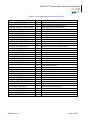
Table 16. Serial Commands (Serial Interface Mode)
Define
CMD_MD_STATUS_READ
CMD_LG_AMBIENT_READ
CMD_MD_CONFIG_STATUS_READ
CMD_MD_CONFIG_STATUS_WRITE
CMD_DELAY_TIME_READ
CMD_DELAY_TIME_WRITE
CMD_HYPERSENSE_READ
CMD_HYPERSENSE_WRITE
CMD_FREQ_RESP_READ
CMD_FREQ_RESP_WRITE
CMD_MD_SUSPEND_READ
CMD_MD_SUSPEND_WRITE
CMD_VERSION_READ
CMD_SER_INTERFACE_READ
CMD_SER_INTERFACE_WRITE
CMD_LG_THRESH_READ
CMD_LG_THRESH_WRITE
CMD_REAL_TIME_MD_READ
CMD_REAL_TIME_MD_WRITE
CMD_MD_OUT_STATE_READ
CMD_MD_OUT_STATE_WRITE
CMD_PING_READ
CMD_PING_WRITE
CMD_RANGE_CONTROL_READ
CMD_RANGE_CONTROL_WRITE
CMD_SENS_READ
CMD_SENS_WRITE
CMD_DUAL_DIRECTION_READ
CMD_DUAL_DIRECTION_WRITE
CMD_DIRECTION_READ
CMD_DIRECTION_WRITE
CMD_RESET_REQUEST
CMD_SLEEP_TIME_READ
CMD_SLEEP_TIME_WRITE
CMD_SLEEP_REQUEST
AN030704-1110
Value
‘a’
‘b’
‘c’
‘C’
‘d’
‘D’
‘e’
‘E’
‘f’
‘F’
‘h’
‘H’
‘i’
‘k’
‘K’
‘l’
‘L’
‘m’
‘M’
‘o’
‘O’
‘p’
‘P’
‘r’
‘R’
‘s’
‘S’
‘u’
‘U’
‘v’
‘V’
‘X’
‘y’
‘Y’
‘Z’
Description
Read Motion Status
Read Current Light Gate Input Level
Read /MD//RST Pin Configuration
Write /MD//RST Pin Configuration
Read /MD Activation Time
Write /MD Activation Time
Read Hyper Sense Setting
Write Hyper Sense Setting
Read Frequency Response Setting
Write Frequency Response Setting
Read Motion Detection Suspend Setting
Write Motion Detection Suspend Setting
Read Module S/W Version
Read Serial Interface Command Mode
Write Serial Interface Command Mode
Read Light Gate Threshold
Write Light Gate Threshold
Read Motion Detected Unsolicited Mode
Write Motion Detected Unsolicited Mode
Read /MD Current Output Active Time
Write /MD Output State
Read Pulse Count
Write Pulse Count
Read Range Setting
Write Range Setting
Read Sensitivity
Write Sensitivity
Read Dual Directional Mode
Write Dual Directional Mode
Read Single Directional Mode
Write Single Directional Mode
Module Reset
Read Sleep Time
Write Sleep Time
Sleep Mode
Page 22 of 32
ZMOTIONTM Detection Module Application Walkthrough
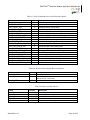
Table 17. Serial Command States (Serial Interface Mode)
Define
ZDOT_IDLE
ZDOT_SENS_SET
ZDOT_DELAY_SET
ZDOT_2PULSE_SET
ZDOT_FREQ_SET
ZDOT_SLEEP_SET
ZDOT_LG_THRESH_SET
ZDOT_MD_STATE_SET
ZDOT_DIR_SET
ZDOT_RESET_SET
ZDOT_REAL_TIME_MD_SET
ZDOT_MD_CONFIG_SET
ZDOT_HYPER_SET
ZDOT_MD_SUSPEND_SET
ZDOT_SLEEP_PIN_SET
ZDOT_SLEEP_TIME_SET
ZDOT_PING_WRITE
ZDOT_RANGE_CONTROL_SET
ZDOT_DUAL_DIR_SET
ZDOT_SER_INTERFACE_SET
Value
0
1
2
3
4
5
6
7
8
9
10
11
12
13
14
15
16
17
18
19
Description
Idle State
Handle the Sensitivity Change state
Handle the Delay Change state
UNUSED
Handle the Freq. Response Change state
Handle the Sleep Mode state
Handle the Light Gate Threshold Change state
Handle the /MD Output State Change state
Handle the Direction Change state
Handle the Reset Request state
Handle the Real-Time MD Status Change state
Handle the /MD Config Change state
Handle the Hypersense Change state
Handle the MD Suspend Status Change state
UNUSED
Handle the Sleep Duration Change state
Handle the Ping write request
Handle the Range Control Change state
Handle the Dual Direction Change state
Handle the Serial Interface Mode state
Table 18. Motion Alarm Output Macro Definitions
Define
ALARM_PORT
ALARM_ON
Value
PAOUT
FBh
ALARM_OFF
~FBh
Description
Motion Alarm Port
Motion Alarm Activation mask
(/MD is on PA2 - active low)
Motion Alarm Deactivation mask
Table 19. Inline Assembly Macros
Define
Z8_NOP
Z8_WDT
Z8_HALT
Z8_STOP
Z8_ATM
AN030704-1110
Function
asm("NOP")
asm("WDT")
asm("HALT")
asm("STOP")
asm("ATM")
Description
Do nothing
Refresh the watch-dog timer
Enter "Halt" mode
Enter "Stop" mode
DI for the next 3 assembly instructions
Page 23 of 32
ZMOTIONTM Detection Module Application Walkthrough
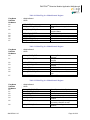
Table 20. Main Flag for cModuleStatus1 Register
Flag Name
Data Size
Bit Names
b0
b1
: cModuleStatus1
: UINT8
:
SER_BYTE_RX
SER_MOTION_DETECTED
b2
SER_REAL_TIME_MD
b3
b4
b5
b6
b7
SER_MD_IS_RESET
SER_BYTE_TX
SER_PIR_STABLE
SER_SLEEP_REQ
SER_MODE_ENABLE
1:Serial byte receive
1:Motion detected copy for Serial
mode
1:Serial sends real-time Motion
Detected Status
1:MD is reset in serial mode
1:Serial Byte to Transmit
1:PIR sensor is stable after power-up
1:Sleep Mode request
1:Enable Serial Interface Mode
Table 21. Main Flag for cModuleStatus2 Register
Flag Name
Data Size
Bit Names
b0
: cModuleStatus2
: UINT8
:
SCAN_SENSE_POT
b1
SCAN_DELAY_POT
b2
b3
MOD2_FFU04
SCAN_LIGHT_GATE
b4
b5
b6
MOD2_FFU10
MOD2_FFU20
SCAN_REQUEST_NEW
b7
REQUEST_SCAN
1:Sensing Enable current channel
scanned
1:Delay Enable current channel
scanned
0:RESERVE-Must be 0
1:Light Gate Enable current channel
scanned
0:RESERVE-Must be 0
0:RESERVE-Must be 0
1:Enable Request new ADC channel
scan
1:Enable Time to request a scan
Table 22. Main Flag for cModuleStatus3 Register
Flag Name
Data Size
Bit Names
b0
b1
b2
b3
b4
: cModuleStatus3
: UINT8
:
DUAL_DIR_ENABLED
SINGLE_DIR_ENABLED
POSITIVE_DIRECTION
LOW_FREQ
ASCII_MODE_ON
b5
RXDATA_OK
b6
GEN_ERROR_FLAG
AN030704-1110
1:Dual Direction Mode Enable
1:Single Direction Mode Enable
1:Motion is positive direction
1:Low frequency response enabled
1:Serial Interface Command Mode
Enabled
1:Indicates that the data being
returned by cSerialRx is valid
1:General error flag passed between
functions
Page 24 of 32
ZMOTIONTM Detection Module Application Walkthrough
b7
AN030704-1110
RESERVE
0: RESERVE-Must be 0
Page 25 of 32
ZMOTIONTM Detection Module Application Walkthrough
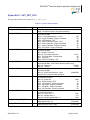
Appendix F—API_INIT_06.h
This appendix describes the contents of API_INIT_06.h.
Table 23. Serial Command States
Define
EPIR_SENSITIVITY_DEF
Value
16
EPIR_SC0_DEF
00h
EPIR_SC1_DEF
28h
EPIR_SC2_DEF
02h
EPIR_SC3_DEF
00h
EPIR_ASC0_DEF
00h
EPIR_ASC2_DEF
5Ah
EPIR_SAMPLE_SIZE_DEF
20h
EPIR_DEBOUNCE_DEF
64h
AN030704-1110
Description
ePIR Sensitivity Register Default Configuration for Normal Scan
Rate. The lower the value, the greater sensitivity.
ePIR Serial Command Register 0 Default Configuration for
Normal Scan Rate
Bit 6-7 - Extended Detection - Level 0
(00)
Bit 5 - Engine Disabled - Engine Controlled
(0)
Bit 4 - MD Suspend - OFF
(0)
Bit 3 - Motion Direction Control – OFF
(0)
Bit 2 - Motion Direction - Engine Controlled
(0)
Bit 1 - Motion Detected - Engine Controlled
(0)
Bit 0 - PIR Stable - Engine Controlled
(0)
ePIR Serial Command Register 1 Default Configuration for
Normal Scan Rate
Bit 7 - Engine Timer Tick
Bits 6-3 - Frequency Response
(0101)
Bit 2 - PIR Scan Rate - Normal Mode
(0)
Bit 1 - Reserved
(0)
Bit 0 - Dual Pyro Enable – OFF
(0)
ePIR Serial Command Register 2 Default Configuration for
Normal Scan Rate. Lower values provide greater range.
Bits 7-3 - Reserved
(00000)
Bits 2-0 – Range
(010)
ePIR Serial Command Register 3 Default Configuration for
Normal Scan Rate
Bits 7-0 - ANAx Scan Request – None
(00000000)
No ADC Scan requests made during Init
ePIR Analog Serial Command Register 0 Default Configuration
for Normal Scan Rate
Bits 7-5 - Reserved
(000)
Bit 4 - Buffer Refresh - OFF
0)
Bit 3 - New Sample - Engine Controlled
(0)
Bit 2 - MD Origin - Engine Controlled
(0)
Bit 1 - EM Noise - Engine Controlled
(0)
Bit 0 - EM Transient - Engine Controlled
(0)
ePIR Analog Serial Command Register 2 Default Configuration
for Normal Scan Rate
Bits 7-5 - Lock Level - 2
(010)
Bits 4-3 - Window Size - 3
(11)
Bits 2-0 - Window Update Rate – 2
(010)
ePIR Sample Size Default Value for Normal Scan Rate
ePIR Sample Size - 32
(00100000)
ePIR Debounce Time Default Value for Normal Scan Rate
ePIR Debounce Time - 0x64
(01100100)
Page 26 of 32
ZMOTIONTM Detection Module Application Walkthrough
Define
EPIR_DEBOUNCE_BATCH_DEF
Value
FFh
EPIR_TRANSIENT_SENSE_DEF
00h
EPIR_NOISE_SENSE_DEF
00h
AN030704-1110
Description
ePIR Debounce_Batch Default Value for Normal Scan Rate
ePIR Debounce Batch Size – 255
(11111111)
ePIR Transient_Sense Default Value for Normal Scan Rate
ePIR Transient Sensitivity – Disabled
(00000000)
ePIR Noise Sense Default Value for Normal Scan Rate
ePIR Noise Sensitivity – Disabled
(00000000)
Page 27 of 32
ZMOTIONTM Detection Module Application Walkthrough
Appendix G—ePIR_API.h
This appendix describes the contents of ePIR_API.h.
Table 24. ePIR Enable Register (ePIR_Enable) Enable/Disable Patterns
Define
EPIR_DISABLE_PATTERN
Value
00h
EPIR_ENABLE_PATTERN
11h
Description
Disables all primary engine functions, including motion
detection. Used to temporarily or permanently shut down
the engine.
Enables the ePIR engine. All primary engine functions as
configured in Engine Status/Control Registers are enabled.
Confirmation of enabled status is provided through Engine
Disabled bit in Status/Control Register 0.
Table 25. ePIR Sensitivity Register (ePIR_Sensitivity
Define
ePIR_SENSITIVITY
Value
FFh
Description
(R/W) Register used to adjust the sensitivity of the ePIR
Table 26. ePIR API Status/Control Register 0 (ePIR_SC0)
Define
SC0_PIR_STABLE
SC0_MOTION_DETECTED
SC0_MOTION_DIRECTION
SC0_DIRECTION_CONTROL
SC0_MD_SUSPEND
SC0_ENGINE_DISABLED
SC0_EXTENDED
Value
01h
02h
04h
08h
10h
20h
C0h
Description
(R) Status/Control Register 0 PIR Stable
(R/W) Status/Control Register 0 Motion Detected
(R) Status/Control Register 0 Motion Direction
(R/W) Status/Control Register 0 Direction Control
(R/W)Status/Control Register 0 Motion Detection Suspend
(R) Status/Control Register 0 Engine Disabled
(R/W) Status/Control Register 0 Extended
Table 27. ePIR API Status/Control Register 1 (ePIR_SC1)
Define
SC1_DUAL_PYRO_ENABLE
SC1_BIT1_RESERVED
SC1_PIR_SCAN_RATE
SC1_FREQUENCY_RESPONSE
SC1_ENGINE_TIMER_TICK
AN030704-1110
Value
01h
02h
04h
78h
80h
Description
(R/W) Status/Control Register 1 Dual Pyro Enable
(R) Status/Control Register 1 Bit1 Reserved
(R/W) Status/Control Register 1 PIR Scan Rate
(R/W) Status/Control Register 1 Frequency Response
(R/W) Status/Control Register 1 Engine Timer Tick
Page 28 of 32
ZMOTIONTM Detection Module Application Walkthrough
Table 28. ePIR API Status/Control Register 2 (ePIR_SC2)
Define
SC2_BIT34567_RESERVED
SC2_RANGE_CONTROL
Value
F8h
07h
Description
(Reserve) Status/Control Register 2 Bit34567 Reserved
(R/W) Status/Control Register 2 Range Control
Table 29. ePIR API Status/Control Register 3 (ePIR_SC3)
Define
SC3_ANA0_SCAN_REQUEST
SC3_ANA1_SCAN_REQUEST
SC3_BIT2_RESERVED
SC3_ANA3_SCAN_REQUEST
SC3_ANA4_SCAN_REQUEST
SC3_ANA5_SCAN_REQUEST
SC3_ANA6_SCAN_REQUEST
SC3_ANA7_SCAN_REQUEST
Value
01h
02h
04h
08h
10h
20h
40h
80h
Description
(R/W) Status/Control Register 3 Analog0 Scan Request
(R/W) Status/Control Register 3 Analog1 Scan Request
(Reserve) Status/Control Register 3 BIT2 Reserve
(R/W) Status/Control Register 3 Analog3 Scan Request
(R/W) Status/Control Register 3 Analog4 Scan Request
(R/W) Status/Control Register 3 Analog5 Scan Request
(R/W) Status/Control Register 3 Analog6 Scan Request
(R/W) Status/Control Register 3 Analog7 Scan Request
Advanced API Registers
The following tables describe the advanced API registers.
Table 30. ePIR Advanced API Status/Control Register 0 (ePIR_ASC0)
Define
ASC0_TRANSIENT_DETECTED
ASC0_NOISE_DETECTED
ASC0_MD_ORIGIN
ASC0_NEW_SAMPLE
ASC0_BUFFER_REFRESH
ASC0_EXTENDED_DETECTION
ASC0_BIT6_RESERVED
ASC0_BIT7_RESERVED
Value
01h
02h
04h
08h
10h
20h
40h
80h
Description
(R/W) API Status/Control Register 0 Transient Detected
(R/W) API Status/Control Register 0 Noise Detected
(R) API Status/Control Register 0 Motion Detection Origin
(R/W) API Status/Control Register 0 New Sample
(R/W) API Status/Control Register 0 Buffer Refresh
(R/W) API Status/Control Register 0 Extended Detection
(Reserve) API Status/Control Register 0 Bit6 Reserve
(Reserve) API Status/Control Register 0 Bit7 Reserve
Table 31. ePIR Advanced API Status/Control Register 2 (ePIR_ASC2)
Define
ASC2_WINDOW_UPDATE_RATE
ASC2_WINDOW_SIZE
ASC2_LOCK_LEVEL
AN030704-1110
Value
07h
18h
E0h
Description
(R/W) API Status/Control Reg. 2 Window Update Rate
(R/W) API Status/Control Reg.2 Window Size
(R/W) API Status/Control Reg.2 Lock Level
Page 29 of 32
ZMOTIONTM Detection Module Application Walkthrough
Table 32. ePIR Process Rate Register (ePIR_Process_Rate)
Define
ePIR_PROCESS_RATE
Value
FFFFh
Description
(R) ePIR Process Rate
Table 33. ePIR Sample Size Register (ePIR_Sample_Size)
Define
ePIR_SAMPLE_SIZE
Value
FFh
Description
(R/W) ePIR Sample Size
Table 34. ePIR Debounce Time Register (ePIR_Debounce)
Define
ePIR_DEBOUNCE_TIME
Value
FFh
Description
(R/W) ePIR Debounce Time
Table 35. ePIR Transient Sensitivity Level Register (ePIR_Transient_Sense)
Define
ePIR_TRANSIENT_SENSE
ePIR_TRANSIENT_SENSE_BIT7_RESERVED
Value
7Fh
80h
Description
(R/W) ePIR Transient Sense
(Reserve)
Table 36. ePIR Noise Sensitivity Register (ePIR_Noise_Sense)
Define
ePIR_NOISE_SENSE
ePIR_NOISE_SENSE_BIT7_RESERVED
Value
7Fh
80h
Description
(R/W) ePIR Noise Sense
(Reserve)
Table 37. ePIR Signal Register (ePIR_Signal)
Define
ePIR_SIGNAL
Value
FFFFh
Description
(R) ePIR Signal
Table 38. ePIR DC Signal Register (ePIR_DC_Signal)
Define
ePIR_DC_SIGNAL
AN030704-1110
Value
FFFFh
Description
(R) ePIR DC Signal
Page 30 of 32
ZMOTIONTM Detection Module Application Walkthrough
Table 39. ePIR Engine Entry Macro Definitions
Define
EPIR_INIT
EPIR_ADC_ISR
AN030704-1110
Description
Initialized the peripherals such as ADC and GPIO; ADC IRQ is set to
medium priority.
Initialized Interrupt for ADC. All the motion detected is executed by this
macro.
Page 31 of 32
ZMOTIONTM Detection Module Application Walkthrough
Warning:
DO NOT USE IN LIFE SUPPORT
LIFE SUPPORT POLICY
ZILOG'S PRODUCTS ARE NOT AUTHORIZED FOR USE AS CRITICAL COMPONENTS IN LIFE
SUPPORT DEVICES OR SYSTEMS WITHOUT THE EXPRESS PRIOR WRITTEN APPROVAL OF THE
PRESIDENT AND GENERAL COUNSEL OF ZILOG CORPORATION.
As used herein
Life support devices or systems are devices which (a) are intended for surgical implant into the body, or (b)
support or sustain life and whose failure to perform when properly used in accordance with instructions for use
provided in the labeling can be reasonably expected to result in a significant injury to the user. A critical
component is any component in a life support device or system whose failure to perform can be reasonably
expected to cause the failure of the life support device or system or to affect its safety or effectiveness.
Document Disclaimer
©2010 by Zilog, Inc. All rights reserved. Information in this publication concerning the devices, applications,
or technology described is intended to suggest possible uses and may be superseded. ZILOG, INC. DOES
NOT ASSUME LIABILITY FOR OR PROVIDE A REPRESENTATION OF ACCURACY OF THE
INFORMATION, DEVICES, OR TECHNOLOGY DESCRIBED IN THIS DOCUMENT. ZILOG ALSO
DOES NOT ASSUME LIABILITY FOR INTELLECTUAL PROPERTY INFRINGEMENT RELATED IN
ANY MANNER TO USE OF INFORMATION, DEVICES, OR TECHNOLOGY DESCRIBED HEREIN OR
OTHERWISE. The information contained within this document has been verified according to the general
principles of electrical and mechanical engineering.
ZMOTION is a trademark of Zilog, Inc. All other product or service names are the property of their respective
owners.
AN030704-1110
Page 32 of 32