1
SAILOR 6282 AIS Transponder
SAILOR 6280/6281 AIS System
User manual
98-135323.book Page i Wednesday, March 12, 2014 3:59 PM
SAILOR 6282 AIS Transponder
SAILOR 6280/6281 AIS System
User Manual
Document number: 98-135323-C
Release date: March 12, 2014
i
98-135323.book Page ii Wednesday, March 12, 2014 3:59 PM
Disclaimer
Any responsibility or liability for loss or damage in connection with the use of this
product and the accompanying documentation is disclaimed by Thrane & Thrane
A/S. The information in this manual is provided for information purposes only, is
subject to change without notice and may contain errors or inaccuracies. Manuals
issued by Thrane & Thrane A/S are periodically revised and updated. Anyone relying
on this information should acquire the most current version e.g. from
www.cobham.com/satcom > Service and support, or from the distributor. Thrane &
Thrane A/S is not responsible for the content or accuracy of any translations or
reproductions, in whole or in part, of this manual from any other source.
Thrane & Thrane A/S is trading as Cobham SATCOM.
Copyright
© 2014 Thrane & Thrane A/S. All rights reserved.
Trademark Acknowledgements
•
SAILOR is a registered trademark of Thrane & Thrane A/S in the European Union
and the Unites States of America and other countries.
•
Other product and company names mentioned in this manual may be trademarks
or trade names of their respective owners.
•
This product contains Android™ software. Android is a trademark of Google Inc.
GPL notification
The software included in this product contains copyrighted software that is licensed
under the GPL/LGPL. The verbatim licenses can be found online at:
http://www.gnu.org/licenses/old-licenses/gpl-2.0.html
http://www.gnu.org/licenses/old-licenses/lgpl-2.1.html
You may obtain the complete corresponding source code from us for a period of
three years after our last shipment of this product, which will be no earlier than 2021,
by sending a money order or check for DKK 50 to:
SW Technology/GPL Compliance,
Thrane & Thrane A/S,
Lundtoftegaardsvej 93D
2800 Lyngby
DENMARK
Write "source for product SAILOR 6282 AIS Transponder" in the memo line of your
payment. This offer is valid to anyone in receipt of this information.
https://www.cobham.com/about-cobham/aerospace-and-security/aboutus/satcom/free-and-open-source-software-(foss).aspx
ii
98-135323.book Page iii Wednesday, March 12, 2014 3:59 PM
Safety summary
Observe the following general safety precautions during all phases of
operation, service and repair of this equipment. Failure to comply with
these precautions or with specific warnings elsewhere in this manual
violates safety standards of design, manufacture and intended use of the
equipment. Thrane & Thrane A/S assumes no liability for the customer's
failure to comply with these requirements.
Ground the equipment
To minimise shock hazard, connect the SAILOR 6282 AIS Transponder to
an electrical ground and follow the cable instructions.
RF exposure hazards and instructions
The SAILOR unit generates electromagnetic RF energy when transmitting.
To ensure that you and those around you are not exposed to excessive
amounts of energy and to avoid health hazards from excessive exposure
to RF energy, all persons must be at least 0.2 m away from the antenna
when the unit is transmitting.
Warranty limitation
IMPORTANT - The SAILOR 6285 GPS Antenna – Active is a sealed
waterproof unit (classified IPx6 & IPx8). To create and maintain its
waterproof integrity it was assembled in a controlled environment using
special equipment. The SAILOR 6282 AIS Transponder is not a user
maintainable unit, and under no circumstances should the unit be opened
except by authorized personnel. Unauthorized opening of the unit will
invalidate the warranty.
Installation and service
Installation and general service must be done by skilled service personnel.
Compass safe distance
Compass safe distance: 55 cm (Standard magnetic compass), 45 cm
(Emergency magnetic compass) from the SAILOR 6282 AIS Transponder
or the SAILOR 6283 AIS Connection Box and Wall Tray.
iii
98-135323.book Page iv Wednesday, March 12, 2014 3:59 PM
Preface
Approvals
The SAILOR 6282 AIS Transponder fulfills the requirements of
the Marine Equipment Directive 96/98/EC with 8th amend
2012/32/EU and is intended for use in maritime environment.
The SAILOR 6282 AIS Transponder is approved to MED
2011/75/EU and fulfills the requirements in the standards: IEC
61993-2 (2012), IEC 60945 ed.4 (2002), ITU-R M.1371-4, IEC
61162-1 (2010), IEC61162-2 (1999).
The SAILOR 6282 AIS Transponder is approved to FCC CFR47
part 80 with USCG approval no.
165.155/0168/BABT/MED000046/0575.
The SAILOR 6282 AIS Transponder is approved for Inland AIS
according CCNR VTT Standard Ed. 1.2 and Inland AIS Test
standard De 2.0.
The SAILOR 6282 AIS Transponder is approved to IC and fulfills
the requirements in RSS-182.
The approvals of the SAILOR 6282 AIS Transponder are
constantly monitored. New national approvals will be applied for
and granted and new test standards may come into force.
Therefore the above list may not be complete. Contact your
authorized dealer for more information.
iv
98-135323.book Page v Wednesday, March 12, 2014 3:59 PM
Training information
The SAILOR 6282 AIS Transponder is designed for occupational
use only and is also classified as such. It must only be used in
the course of employment by individuals aware of the hazards
as well as the way to minimize those hazards.
The unit is thus NOT intended for use in an uncontrolled
environment by general public. The SAILOR 6282 AIS
Transponder has been tested and complies with the FCC RF
exposure limits for Occupational Use Only. The unit also
complies with the following guidelines and standards regarding
RF energy and electromagnetic energy levels including the
recommended levels for human exposure:
•
FCC OET Bulletin 65 Supplement C, evaluating compliance
with FCC guidelines for human exposure to radio frequency
electromagnetic fields.
•
American National Standards Institute (C95.1) IEEE standard
for safety levels with respect to human exposure to radio
frequency electromagnetic fields, 3 kHz to 300 GHz.
•
American National Standards Institute (C95.3) IEEE
recommended practice for the measurement of potentially
hazardous electromagnetic fields - RF and microwaves.
Below is a description of the RF exposure hazards and
instructions in safe operation of the unit within the FCC RF
exposure limits established for it.
Warning
Your SAILOR unit generates electromagnetic RF (radio
frequency) energy when it is transmitting. To ensure that you
and those around you are not exposed to excessive amounts of
that energy (beyond FCC allowable limits for occupational use)
and thus to avoid health hazards from excessive exposure to RF
energy, FCC OET bulletin 65 establishes a Maximum Permissible
Exposure (MPE) radius of 0.2 m for the maximum power of your
unit (12.5 W selected) with a half wave omni-directional
antenna having a maximum gain of 3 dB (5.2 dBi). This means all
v
98-135323.book Page vi Wednesday, March 12, 2014 3:59 PM
persons must be at least 0.2 m away from the antenna when the
unit is transmitting.
Alerte de Sécurité
Dangers liés á l'exposition aux fréquences radio et instructions.
Conformément á la réglementation d'industrie Canada, le
present radio emetteur ne peut fonctionner qu'avec une
antenne de type omnidirectionelle, demi-onde ou d'un gain
maximale de 3 dB, approuvée par Industrie Canada. Pour éviter
les risques pour la santé dûs á une exposition excessive aux
champs de fréquences radio, une distance minimale de 0.2 m est
nécessaire entre l'utilisateur et le radio-émetteur.
Installation
The SAILOR 6282 AIS Transponder is designed for installation
by a skilled service person.
1. An omni-directional antenna with a maximum power gain of
5.2 dBi must be mounted at least 2.2 m above the highest
deck where people may be staying during radio
transmissions. The distance is to be measured vertically from
the lowest point of the antenna. This provides the minimum
separation distance which is in compliance with RF exposure
requirements and is based on the MPE radius of 0.2 m plus
the 2 m height of an adult.
2. On vessels that cannot fulfill requirements in item 1, the
antenna must be mounted so that its lowest point is at least
0.2 m vertically above the heads of people on deck and all
persons must be outside the 0.2 m MPE radius during radio
transmission.
•
Always mount the antenna at least 0.2 m from possible
human access.
•
Never touch the antenna when transmitting
•
Use only authorized SAILOR accessories.
3. If the antenna has to be placed in public areas or near people
with no awareness of the radio transmission, the antenna
vi
98-135323.book Page vii Wednesday, March 12, 2014 3:59 PM
must be placed at a distance not less than 1.8 m from
possible human access.
Failure to observe any of these warnings may cause you or other
people to exceed FCC RF exposure limits or create other
dangerous conditions.
About the manual
Intended readers
This manual is a user manual for the SAILOR 6282 AIS
Transponder system. This manual is intended for anyone who is
using or intends to use this system. No specific skills are required
to operate the SAILOR 6282 AIS Transponder. However, it is
important that you observe all safety requirements listed in the
beginning of this manual, and operate the system according to
the guidelines in this manual.
Note that this manual does not cover installation of the system.
For information on installation refer to the installation manual.
Part numbers for related manuals are listed in the next section.
vii
98-135323.book Page viii Wednesday, March 12, 2014 3:59 PM
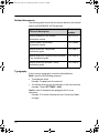
Related documents
The following table shows the documents related to this manual
and to the SAILOR 6282 AIS Transponder.
Title and description
Document
number
SAILOR 6280/6281 AIS System,
Installation manual
98-137573
SAILOR 6004 Control Panel,
Installation manual
98-136644
SAILOR 6282 AIS Transponder,
Installation guide
98-136017
SAILOR 6283 AIS Connection Box and Wall
Tray, Installation guide
98-136018
SAILOR 6285 GPS Antenna - Active,
Installation guide
98-136019
Typography
In this manual, typography is used as indicated below:
Bold is used for the following purposes:
•
•
To emphasize words.
Example: “Do not touch the antenna”.
To indicate what the user should select in the user interface.
Example: “Select SETTINGS > LAN”.
Italic is used to emphasize the paragraph title in crossreferences.
Example: “For further information, see Connecting Cables
on page...”.
viii
98-135323.book Page ix Wednesday, March 12, 2014 3:59 PM
Table of contents
Chapter 1
Introduction
Introduction to AIS .............................................................................1
The SAILOR 6280/6281 AIS System ..........................................4
System components ...........................................................................6
Chapter 2
Operation
To get started .........................................................................................9
Settings ................................................................................................... 15
To work with messages ................................................................... 33
Alarms and notifications ................................................................ 39
List of alarms ........................................................................................ 41
Chapter 3
Service & maintenance
Maintenance ........................................................................................ 49
Troubleshooting guide .................................................................... 56
Service and repair .............................................................................. 58
App. A
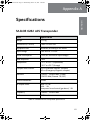
Specifications
SAILOR 6282 AIS Transponder .................................................. 61
SAILOR 6285 GPS Antenna - Active ......................................... 64
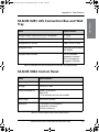
SAILOR 6283 AIS Connection Box and Wall Tray ............ 65
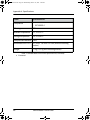
SAILOR 6004 Control Panel .......................................................... 65
ix
98-135323.book Page x Wednesday, March 12, 2014 3:59 PM
Table of contents
App. B
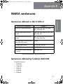
NMEA sentences
Sentences defined in IEC 61993-2 ........................................... 67
Sentences defined by Cobham SATCOM .............................. 67
Glossary
..................................................................................................................... 69
Index
..................................................................................................................... 73
x
98-135323.book Page 1 Wednesday, March 12, 2014 3:59 PM
11111
Chapter 1
Introduction
Introduction
1
This chapter introduces the SAILOR 6282 AIS Transponder and gives an
overview of the system and services. It has the following sections:
•
Introduction to AIS
•
The SAILOR 6280/6281 AIS System
•
System components
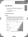
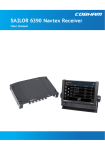
Introduction to AIS
Overview
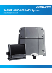
AIS (Automatic Identification System) is a communication system for the
exchange of navigation data. An AIS station can be a ship station or a
shore-side base station. AIS stations operate without interaction by ship or
shore personnel (autonomous and continuous). AIS has evolved to include
devices such as AIS as a navigation aid, AIS on search and rescue aircraft
and AIS search and rescue transmitters (AIS SART).
Figure 1: AIS for exchange of data
1
98-135323.book Page 2 Wednesday, March 12, 2014 3:59 PM
Chapter 1: Introduction
AIS enables the automatic exchange of shipboard information from the
vessel's sensors (dynamic data), as well as manually entered static and
voyage related data, between one vessel and another and between a vessel
and a shore station(s). AIS also provides the possibility to send short safety
related text messaging for ship or shore personnel. AIS devices are required
internationally on most commercial vessels as identified by the
International Maritime Organization (IMO) in the Safety of Life at Sea
Convention (SOLAS), Chapter V. In addition, AIS is often required
domestically on other vessels by some administrations.
AIS applications and purpose
The principal applications of AIS are:
•
Information exchange between vessels within VHF range of each other,
increasing situation awareness
•
Information exchange between a vessel and a shore station, such as a
Vessel Traffic Service (VTS), to improve traffic management in
congested waterways
•
Automatic reporting in areas of mandatory and voluntary reporting
•
Exchange of safety related information between vessels and between
vessels and shore station(s).
The purpose of AIS is to improve the safety of navigation and protection of
the environment by assisting in the effective navigation of ships and the
operation of VTS. This is achieved through the following:
2
•
In a ship-to-ship mode for collision avoidance
•
As a means for littoral states to obtain information about a ship and its
cargo
•
As a VTS tool, i.e. ship-to-shore, for traffic management
•
Increased situational awareness which enables effective response to
emergencies such as search and rescue (SAR) as well as environmental
pollution
•
Providing data to identify trends or improvements to enhance
navigational safety.
Introduction to AIS
98-135323.book Page 3 Wednesday, March 12, 2014 3:59 PM
11111
Note
Not all ships are required to have AIS. Furthermore, AIS may be
switched off if there is a potential risk that the operation of AIS
might compromise the safety or security of the ship, or if security
incidents are imminent.
If a vessel operating in a mandatory ship reporting system does switch off
its AIS, this should be reported to the relevant authority. Note that some
data is entered or updated manually, meaning that there is potential for
false entry and for the entered data to become out of date. This includes
data related to static information (e.g. ship identity, dimension) and voyage
related data (e.g. navigational status).
AIS and radar
A difference between AIS and radar is that AIS uses an absolute referencing
system to determine the position, whereas radar determines the position by
relative measurements from the vessel or shore base to observed targets.
AIS may be used together with radar information to provide:
•
Vessel identification, heading, course over ground (COG) and speed over
ground (SOG)
•
Improved vessel tracking (no target swap)
•
Wider geographical coverage
•
Greater positional accuracy, dependent on the position input sensor
•
Information in radar shadow area ('sees' around bends and behind
islands)
•
Maneuver data in nearly real time
•
No loss of targets in sea, rain and snow clutter
AIS classes
AIS is not only used on board ships. It can be grouped by 'class' (shipborne)
and function. A Ship borne AIS device which contributes by most of the
flow of AIS information, is classified as either Class A, B or Inland AIS. The
AIS Class A stations are ship borne units which meet IMO performance
standards and are required on most commercial ships by the International
Maritime organization (IMO). The SAILOR 6282 AIS Transponder is a a
combined Class A and Inland AIS station.
Introduction to AIS
3
Introduction
Chapter 1: Introduction
98-135323.book Page 4 Wednesday, March 12, 2014 3:59 PM
Chapter 1: Introduction
The SAILOR 6280/6281 AIS System
The SAILOR 6280 AIS System consists of the following units:
1. SAILOR 6282 AIS Transponder
2. SAILOR 6285 GPS Antenna - Active
3. SAILOR 6004 Control Panel
4. SAILOR 6283 AIS Connection Box and Wall Tray
The SAILOR 6281 AIS Basic System consists of the following units:
1. SAILOR 6282 AIS Transponder
2. SAILOR 6285 GPS Antenna - Active
3. SAILOR 6004 Control Panel
4
The SAILOR 6280/6281 AIS System
98-135323.book Page 5 Wednesday, March 12, 2014 3:59 PM
11111
Chapter 1: Introduction
Introduction
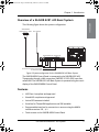
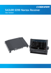
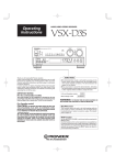
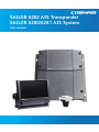
Overview of a SAILOR 6281 AIS Basic System
The following figure shows the system configuration.
SAILOR 6285
GPS Antenna - Active
VHF Antenna
SAILOR 6004 Control Panel
SAILOR 6282 AIS Transponder
PWR
TEST
AUX
ACC
1
VHF/GPS
GPS
FUSE
12-24V DC
SUB-D50
12-24 VDC
Connector for interface connections
or connection board
Figure 2: System configuration for the SAILOR 6281 AIS Basic System
The SAILOR 6004 Control Panel is connected to the SAILOR 6282 AIS
Transponder through a LAN connection (LWE/IEC 61162-450), here after
called LWE. The SAILOR 6281 AIS Basic System is operated using the touch
display of the SAILOR 6004 Control Panel.
Features
•
AIS Class A compliant and approved
•
Inland AIS compliant and approved
•
Active GPS antenna included
•
Interface for ThraneLINK applications and INS available
•
Programmable interface for connection to sensors using the NMEA
interface versions 2.0, ...,4.1
•
Touch screen on the SAILOR 6004 Control Panel
The SAILOR 6280/6281 AIS System
5
98-135323.book Page 6 Wednesday, March 12, 2014 3:59 PM
Chapter 1: Introduction
•
Easy installation with the dedicated connection box available (SAILOR
6283 AIS Connection Box and Wall Tray)
•
Easy service - on the unit, through the ThraneLINK Management
Application (TMA) or a web browser
•
Built-in self-diagnostic system
•
Built-in DC output on GPS antenna connector
•
Possibility for a combined VHF and GPS antenna
•
River use compliant with CCNR requirements
•
Works with both GPS and GLONASS
•
Input for Low Power Forced Control, 1W output (gas alarm)
•
Support of Class B carrier sense messages
•
Function for discarding Class B messages
•
Support for Long Range satellite tracking on channel 75 & channel 76
•
Interface for pilot plug
System components
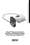
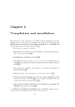
SAILOR 6282 AIS Transponder
The SAILOR 6282 AIS Transponder is a combined Class A and Inland AIS
station. It has connectors for GPS and VHF antenna, a ground stud,
connector for DC power (12–24 VDC), multi connector for interfaces and
2 LAN connectors. The SAILOR 6282 AIS Transponder is always on,
provided there is DC power.
The SAILOR 6282 AIS Transponder supports 3 sensor inputs for e.g. GPS
and ROT and 4 presentation interfaces for e.g. ECDIS, Radar, Long Range
and Pilot Plug. It also has inputs for Blue Sign functionality, Low Power
Forced Control (gas alarm) and output for alarm. The SAILOR 6282 AIS
Transponder has three LEDs showing the status of Power, Rx and Tx.
6
System components
98-135323.book Page 7 Wednesday, March 12, 2014 3:59 PM
11111
Introduction
Chapter 1: Introduction
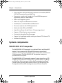
Figure 3: SAILOR 6282 AIS Transponder
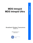
SAILOR 6285 GPS Antenna - Active
The SAILOR 6285 GPS Antenna - Active is a robust, sealed and waterproof
GPS antenna (classified IPx6 & IPx8).
Figure 4: SAILOR 6285 GPS Antenna - Active
SAILOR 6004 Control panel
The SAILOR 6004 Control panel is the user interface for the SAILOR 6282
AIS Transponder. Through the touch panel you access all settings that can
be changed by the user. Alarms and notifications are shown in the display.
The SAILOR 6004 Control panel has a buzzer for alarm tones. The display
supports night mode. The AIS application is loaded into the SAILOR 6004
Control Panel during installation.
System components
7
98-135323.book Page 8 Wednesday, March 12, 2014 3:59 PM
Chapter 1: Introduction
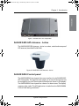
Figure 5: SAILOR 6004 Control panel
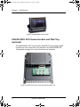
SAILOR 6283 AIS Connection Box and Wall Tray
(optional)
The SAILOR 6283 AIS Connection Box and Wall Tray has spring-loaded
terminals for easy connection of all interfaces. See SAILOR 6282 AIS
Transponder on page 6 for more information on interfaces.
Figure 6: SAILOR 6283 AIS Connection Box and Wall Tray
8
System components
98-135323.book Page 9 Wednesday, March 12, 2014 3:59 PM
22222
Chapter 2
This chapter has the following sections:
•
To get started
•
Settings
•
To work with messages
•
Alarms and notifications
2
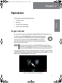
Operation
Operation
To get started
As soon as DC power is provided the SAILOR 6282 AIS Transponder is on.
To switch on the SAILOR 6004 Control Panel push the power
button. Operate the SAILOR 6004 Control Panel by tapping the
touch screen. To switch off the SAILOR 6004 Control Panel
push and hold the power button for 2 seconds and follow the
instructions on the screen.
Note
When the remote switch in the SAILOR 6004 Control Panel is
wired and it is switched on, you can only use the Power button to
reboot the SAILOR 6004 Control Panel, you cannot switch it off.
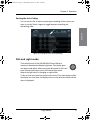
The AIS application has been installed during the installation of the SAILOR
6280/6281 AIS System. To start the AIS application tap the AIS icon in the
display of the SAILOR 6004 Control Panel.
Figure 7: Screen after start-up (example)
9
98-135323.book Page 10 Wednesday, March 12, 2014 3:59 PM
Chapter 2: Operation
The icon System holds the application manager and settings for the
SAILOR 6004 Control panel, for more details see App installation and
system settings on page 52.
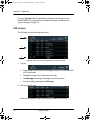
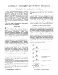
AIS screen
The AIS app has the following idle screen:
1
2
3
Figure 8: Sections in the AIS application screen (example)
1. Top bar
•
Current app, in this case AIS, showing the name of the SAILOR 6282
AIS Transponder.
•
Tab List showing a list of ships near own ship.
•
Tab Messages showing all messages received and sent.
•
Icon for sending messages and Settings.
2. AIS app-specific area
Each row represents a ship and its position relative to own ship.
10
To get started
98-135323.book Page 11 Wednesday, March 12, 2014 3:59 PM
22222
Chapter 2: Operation
•
Details – tap to display a new screen with details for the selected
ship.
•
BRG shows the current bearing value to own ship.
•
RNG shows the current distance (range) in nautical miles (NM)
between own ship and ship in the AIS list.
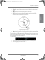
Operation
7UXH1RUWK
2ZQVKLS
%HDULQJ
%5*
5DQJH
51*
6KLSLQ
$,6/LVW
Figure 9: Bearing and range
•
Age shows the number of minutes since this ship last reported data.
The list holds up to 200 targets within VHF range which are closest to own
ship. A ship is cleared from the list after 7-18 minutes. You can sort the list,
see Sorting the list of ships on page 13.
3. Bottom bar
•
Icon for back function and collapsing the on-screen keyboard.
•
Icon for going to the start screen.
To get started
11
98-135323.book Page 12 Wednesday, March 12, 2014 3:59 PM
Chapter 2: Operation
•
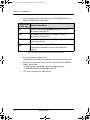
Icons for apps that are operated from this SAILOR 6004 Control
Panel, including status information.
Letters next
Status information
to AIS icon
LR
There are unread Long Range messages. For more
information see page 25.
TXT
The Status information has changed. For more
information see page 20.
LO
The AIS unit is in low-power mode (Low power forced
control (gas alarm)).
TX
Red icon. The AIS unit is in Silent Mode and the
transmitter is disabled. For more information see
page 31.
Table 1: Letters next to the AIS icon in the bottom bar
12
•
Icon for unread messages, if any.
Unread safety messages are marked with a red exclamation mark.
•
Icon for alarms present: from any unit controlled by this SAILOR
6004 Control Panel:
– Flashing bright red triangle: Unacknowledged alarm(s).
– Faded red triangle: Acknowledged alarm(s).
•
UTC time, received from GPS receiver.
To get started
98-135323.book Page 13 Wednesday, March 12, 2014 3:59 PM
22222
Chapter 2: Operation
Sorting the list of ships
Operation
You can sort the list of ships by selecting the heading of the column you
want to sort by. Select it again to toggle between ascending and
descending order.
Figure 10: Sorting the list of ships (example)
Dim and night mode
Turn the dim knob of the SAILOR 6004 Control Panel to
increase or decrease the display brightness. The display goes
into night mode either when turning the dim knob on the front
panel counterclockwise or when the internal light sensor
detects the light level for changing to night mode.
To dim to level zero push the power button once. If an alarm appears while
the display is in level zero, the display returns to the latest dim value and the
alarm is displayed.
To get started
13
98-135323.book Page 14 Wednesday, March 12, 2014 3:59 PM
Chapter 2: Operation
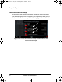
Show the ship details
The SAILOR 6282 AIS Transponder provides details for all ships listed. On
the idle screen, tap the ship that you are interested in. Swipe upwards to
display further items.
Swipe
up or
down
Figure 11: Ship details
14
To get started
98-135323.book Page 15 Wednesday, March 12, 2014 3:59 PM
22222
Chapter 2: Operation
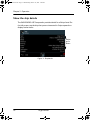
Settings
To access the settings of the SAILOR 6282 AIS Transponder tap the menu
icon and Settings.
Operation
1
2
Figure 12: Accessing Settings
This menu has the following items:
•
Voyage
•
Dynamic Data (read only)
•
Status (read only)
•
Static Data (read only)
•
Inland Waterways
•
Long Range
•
Test Message
•
Channel Management
•
Connection (read only)
•
Internal GNSS (read only)
•
Silent Mode
Note
Only touch-screen keys that are required by the AIS standard
1371-4 table 44 are supported.Other keys are ignored.
Settings
15
98-135323.book Page 16 Wednesday, March 12, 2014 3:59 PM
Chapter 2: Operation
Password protection
A number of settings is password protected against unauthorised or
accidental use. They are marked with a padlock.
Swipe
up or
down
Figure 13: Password protection – example
To unlock a page with password protected parameters do as follows:
1. Tap the first line on the page: Authorize changes.
2. Enter the user level password (default: user). If the password user does
not work, contact your installation center. The user password might
have been changed.
3. Tap Done.
4. Tap Apply.
5. The padlocks are opened and you can change a parameter.
When leaving the page, the parameters are locked again.
16
Settings
98-135323.book Page 17 Wednesday, March 12, 2014 3:59 PM
22222
Chapter 2: Operation
Voyage
Operation
Here you select or enter the various items for the ship’s current voyage.
Swipe upwards to display further items. Some of the parameters are only
visible if Inland Waterways has been enabled. These parameters may have
been set up during installation.
Swipe
up or
down
Figure 14: Settings – Voyage
To change the parameters do as follows:
1. Unlock the page by entering the password.
2. Tap the parameter you want to change and follow the instructions in
the display.
Item
Description
Status
Tap the field Status and set one option.
Destination
Tap the field Destination and enter the destination using the
keyboard on the screen. Tap OK to accept.
ETA
Tap the field ETA to enter the estimated time of arrival.
Format: mm-dd hh:mm. Tap Done.
If ETA is not known, enter xx.
Cargo
Tap the field Cargo and set one option.
Table 2: Items in Voyage
Settings
17
98-135323.book Page 18 Wednesday, March 12, 2014 3:59 PM
Chapter 2: Operation
Item
Description
Draughta
Tap the field Draught and select the draught of ship xx.x m
(0–20).(0–9). Tap Done.
Persons on boarda
Number of crew members, passengers and shipboard
personnel on board.
ERI ship typeb
ERI ship type according to ERI classification, swipe the list and
select the ship type.
Crew Membersb
Number of crew members on board (0 to 8190).
Passengersb
Number of passengers on board (0 to 254).
Shipboard
Personnelb
Number of shipboard personnel on board (0 to 254).
Static Draughtb
Static draught of ship (0 to 20,00 m).
Air draughtb
Air draught of ship (0 to 40,00 m).
Tug Boatsb
Number of assisting tugboat (0-6).
Blue Conesb
Number of blue cones (for cargo classification), 1, 2 or 3 Blue
Cones, B-Flag or Unknown.
Blue Signb
Set automatically by a connected switch or a PI sentence.: Not
available, Not set or Set.
Loadedb
Set to: Not available, Loaded or Not Loaded
Convoy Bowb
Convoy extension to bow in m.dm (resolution in dm).
Convoy Sternb
Convoy extension to stern in m.dm (resolution in dm).
Convoy Portb
Convoy extension to port side in m.dm (resolution in dm).
Convoy Starboardb
Convoy extension to starboard side in m.dm (resolution in
dm).
Table 2: Items in Voyage (Continued)
a. Visible if Inland Waterways is disabled.
b. Visible if Inland Waterways is enabled, see also Figure 18 on page 23.
18
Settings
98-135323.book Page 19 Wednesday, March 12, 2014 3:59 PM
22222
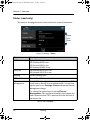
Dynamic Data (read only)
The dynamic data is provided by the ship’s sensors.
Swipe
up or
down
Figure 15: Settings – Dynamic data (read only)
Item
Description
Latitude
Current value for latitude.
Longitude
Current value for longitude.
RAIM
Indication of RAIM being used or not.
Position accuracy > 10 m or <= 10 m.
Position quality
Indication of position quality derived from Position
accuracy, RAIM and Position time stamp.
Time stamp
Time stamp for latest received position update in seconds.
COG
Course over ground, relative to True North.
SOG
Speed over ground.
Heading
1 – True North
2 – Heading
Rate of turn
Right or left, from 0 to 720 degrees per minute.
Table 3: Items in Dynamic Data
Settings
19
Operation
Chapter 2: Operation
98-135323.book Page 20 Wednesday, March 12, 2014 3:59 PM
Chapter 2: Operation
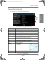
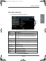
Status (read only)
The items on this page show the current status of a couple of parameters.
Swipe
up or
down
Figure 16: Settings – Status
Item
Description
GNSS
Type of position input:
AIS: External GNSS in use
AIS: Internal GNSS in use
AIS: External DGNSS in use
SOG/COG
AIS: External SOG/COG in use
AIS: Internal SOG/COG in use
Heading
Current Heading input
ROT
Current Rate Of Turn
Channel
Management
If the AIS Transponder enters a received regional area, TXT is
shown next to the AIS icon in the bottom bar. You can then
tap the menu icon > Settings> Status and see the Channel
Management change.
For viewing the regional area in use tap Channel
Management. Once you have viewed this information, this
field is cleared and the TXT is removed from the AIS icon in
the bottom bar.
Table 4: Items in Status
20
Settings
98-135323.book Page 21 Wednesday, March 12, 2014 3:59 PM
22222
Chapter 2: Operation
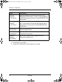
Static Data (read only)
Operation
The static data is entered during installation.
Swipe
up or
down
Figure 17: Settings – Static data (read only)
Item
Description
MMSI
Nine digit number to uniquely identify own ship.
IMO Number
A unique identifier consisting of the three letters IMO
followed by a unique seven-digit number assigned to
own ship.
Name
Name of own ship.
Callsign
Designation of this transmitting station.
EPFS Type
Type of Electronic Position Fixing System installed on
own ship.
Ship Type
Type of own ship.
Numeric ship
type
Type of own ship.
ENI Numbera
ENI number of own ship
Lengtha
Overall length of own ship.
Beama
Width at the widest point.
Table 5: Items in Static Data
Settings
21
98-135323.book Page 22 Wednesday, March 12, 2014 3:59 PM
Chapter 2: Operation
Item
Description
Internal
antennab
A, B, C and D
Physical location of the internal GNSS sensor, e.g.
SAILOR 6285 GPS Antenna - Active, connected directly
to the GPS antenna connector of the SAILOR 6282 AIS
Transponder.
External
antennab
A, B, C and D
Physical location of the external GNSS sensor on own
ship, i.e. the antenna for the main GPS receiver that is
connected to a sensor input of the SAILOR 6282 AIS
Transponder.
Quality of speed
informationa
High or low. Consult the documentation of the
connected speed sensor.
Quality of course High or low. Consult the documentation of the
informationa
connected course sensor.
Quality of
heading
informationa
High or low. Consult the documentation of the
connected heading sensor.
Table 5: Items in Static Data (Continued)
a. Inland Waterways is enabled.
b. Only B and C available when Internal Waterways is enabled.
22
Settings
98-135323.book Page 23 Wednesday, March 12, 2014 3:59 PM
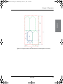
22222
Operation
Chapter 2: Operation
Figure 18: Physical location of GNSS sensor on the ship and in a convoy
Settings
23
98-135323.book Page 24 Wednesday, March 12, 2014 3:59 PM
Chapter 2: Operation
Inland Waterways
On this page you enable the settings for Inland Waterways shown in
Voyage and Static Data, and you can broadcast the number of persons
on board, if requested to do so.
Swipe
up or
down
Figure 19: Settings – Inland Waterways
To enable Inland Waterways do as follows:
1. Unlock the page by entering the password.
2. Tap Inland Waterways to enable it.
When enabled, further fields will be available in Voyage and Static
Data.
To broadcast the number of persons on board (this is the total number of
persons: crew members, shipboard personnel and passengers) do as follows:
1. Unlock the page by entering the password ‘user’.
2. Tap Broadcast number of persons.
3. At Broadcast persons onboard tap Send.
24
Settings
98-135323.book Page 25 Wednesday, March 12, 2014 3:59 PM
22222
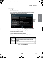
Long Range
The SAILOR 6282 AIS Transponder can broadcast long range messages.
You can manually set which information to include in the long range
message. Swipe upwards to display further items.
Operation
Chapter 2: Operation
Swipe
up or
down
LR is shown if there are
unread Long Range messages
Figure 20: Settings – Long Range
To change a parameter do as follows:
1. Unlock the page by entering the password.
2. Tap the parameter you want to change and follow the instructions in
the display.
Item
Description
Show
Tap here to display the log of received long range
Message Log messages.
Broadcast
Tap Broadcast to enable or disable broadcast of long
range messages.
Table 6: Items in Long Range
Settings
25
98-135323.book Page 26 Wednesday, March 12, 2014 3:59 PM
Chapter 2: Operation
Item
Description
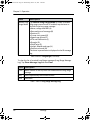
Manual Long Tap Manual Long Range Mode to enable or disable
Range Mode long range manual mode. If enabled, tap the items to
include in the long range message:
• Name, callsign and IMO (A)
• Date and time of message (B)
• Position (C)
• Course over ground (E)
• Speed over ground (F)
• ETA and Destination (I)
• Draught (O)
• Ship/Cargo (P)
• Length, breadth and type (U)
• Persons on board (W)
The letter in parentheses is displayed in the LR message
log.
Table 6: Items in Long Range (Continued)
To clear the list of received Long Range messages (Long Range Message
Log) Tap Show Message Log and then Clear.
Item Description
From
MMSI number of the ship that has broadcasted the long range
message.
Req.
Items requested by the AIS base station.
Sent
Items sent.
Table 7: Items in Long Range Message Log
26
Settings
98-135323.book Page 27 Wednesday, March 12, 2014 3:59 PM
22222
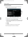
Test Message
Use Test Message to check that the SAILOR 6282 AIS Transponder can
send a text message to and receive a text message from other transponder
systems. This test is done automatically. No action from the message
recipient is required. A target with at suitable range (15-25 NM) is selected
if such a target has been received by the SAILOR 6282 AIS Transponder.
The SAILOR 6282 AIS Transponder supports AIS SART Test messages
and COM Test messages.
To receive an AIS SART Test do as follows:
1. Unlock the page by entering the password.
2. Tap the AIS SART Test selection box to enable the display of AIS
SART Test targets.
To start a COM Test do as follows:
1. Tap the COM Test Target to select a target for testing communication.
This target responds by an automatic acknowledge from the displayed
MMSI number. For each tap the test target changes because there are
some rules to be followed (e.g. the AIS Transponder may not select
closest or most distant target, it must toggle to new target after test
message is sent for new test message)
2. Tap Start COM Test. The test starts and the result of the
communication test is shown on the screen.
Swipe
up or
down
Figure 21: Settings – Test Message (example)
Settings
27
Operation
Chapter 2: Operation
98-135323.book Page 28 Wednesday, March 12, 2014 3:59 PM
Chapter 2: Operation
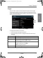
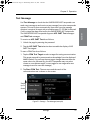
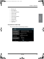
Channel Management
The AIS channel is preset. If required, the AIS parameters (up to 8 sets) can
be changed. The AIS parameters can be changed as follows:
•
AIS message 22 with new parameters (set automatically in the SAILOR
6282 AIS Transponder).
•
Through a received DSC message with new parameters (set
automatically in the SAILOR 6282 AIS Transponder).
•
Manual input of new parameters, e.g. you have received the new
parameters in a text message or via VHF radio.
The SAILOR 6282 AIS Transponder decides which of the frequencies to
use.
Swipe
up or
down
Figure 22: Settings – Channel Management
Entering new AIS parameter set manually
To enter a new area do as follows:
1. Unlock the page by entering the password.
2. Tap New Area and fill in the following parameters:
28
•
Set Area
•
NE Latitude
•
NE Longitude
Settings
98-135323.book Page 29 Wednesday, March 12, 2014 3:59 PM
22222
•
SW Latitude
•
SW Longitude
•
Channel A Frequency
•
Channel A RX
•
Channel A TX
•
Channel B Frequency
•
Channel B RX
•
Channel B TX
•
Transition zone
•
High Power
Operation
Chapter 2: Operation
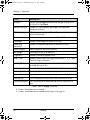
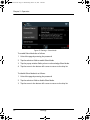
Connection (read only)
The connection data is entered during installation.
Figure 23: Settings – Connection
Settings
29
98-135323.book Page 30 Wednesday, March 12, 2014 3:59 PM
Chapter 2: Operation
Item
Description
Own Device
Name
Identification of the SAILOR 6004 Control Panel in the
network.
Remote Device
Name
Identification of the SAILOR 6282 AIS Transponder in the
network.
Remote IP
IP address of the connected SAILOR 6282 AIS Transponder.
The IP address is needed for setup, service and maintenance.
The IP address is acquired automatically (read only).
Own IP
IP address of the SAILOR 6004 Control Panel. The IP address
is needed for service and maintenance. The IP address is
acquired automatically (read only).
Table 8: Items in Connection
Internal GNSS (read only)
You can view the current signal levels from the GPS satellites.
Tap Internal GNSS.
Figure 24: Settings – Internal GNSS
30
Settings
98-135323.book Page 31 Wednesday, March 12, 2014 3:59 PM
22222
Chapter 2: Operation
Silent Mode
Use Silent Mode only if it is necessary to be invisible, e.g. in a pirate
situation in international waters.
Enabling Silent Mode violates the IMO regulation for GMDSS.
Using Silent Mode will make your vessel non-compliant to
the IMO carriage requirements and is only allowed under
special circumstances. This action must be recorded in the
ship’s log.
If no functional switch is connected1 to the SAILOR 6282 AIS Transponder
you can activate Silent Mode in a menu on the SAILOR 6004 Control Panel.
A warning appears in a popup window on the SAILOR 6004 Control Panel
and an alarm (TX disabled) is logged2. The popup window will be repeated
every twelfth hour as a reminder that the Silent Mode is still active. The
Silent Mode is active after power interruption until it is manually disabled.
When leaving the Silent Mode a warning appears on the SAILOR 6004
Control Panel that the ship is visible again2.
The SAILOR 6282 AIS Transponder cannot acknowledge received
addressed messages in Silent Mode because all transmit activity is disabled
in Silent Mode. Therefore the sender will retransmit the message several
times and the SAILOR 6282 AIS Transponder will display all retransmitted
messages.
1. In the Service Interface, the IO settings for the functional switch must be
set to Not Used or Blue Sign.
2. Only with external switch for Silent Mode.
Settings
31
Operation
Important
98-135323.book Page 32 Wednesday, March 12, 2014 3:59 PM
Chapter 2: Operation
Figure 25: Settings – Silent Mode
To enable Silent Mode do as follows:
1. Unlock the page by entering the password.
2. Tap the selection field to enable Silent Mode.
3. Tap the popup window Safety alarm to acknowledge Silent Mode.
4. Tap the arrow in the bottom left corner to return to the ship list.
To disable Silent Mode do as follows:
1. Unlock the page by entering the password.
2. Tap the selection field to disable Silent Mode.
3. Tap the arrow in the bottom left corner to return to the ship list.
32
Settings
98-135323.book Page 33 Wednesday, March 12, 2014 3:59 PM
22222
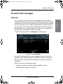
To work with messages
Overview
You can send, broadcast and receive text messages and safety-related
messages (SRM) to and from all ships within VHF range. An unread message
is shown as a closed envelope in the bottom bar of the screen. An envelope
with an exclamation mark is a SART message. White envelopes mean that
new messages have arrived since you last tapped the area for messages in
the lower right corner. Gray envelopes mean that no new messages have
arrived since you last tapped the area for messages.
To view all messages tap the tab Messages in the idle screen.
Figure 26: The tab Messages
The latest 20 addressed safety-related messages are stored (minimum).
Broadcast safety-related messages (e.g. SART) are updated continuously,
the newest one is stored and can be displayed. The oldest messages are
overwritten.
There are two ways of sending a message:
•
Sending a message to a dedicated address (MMSI number)
•
Broadcasting a message to all listeners.
To work with messages
33
Operation
Chapter 2: Operation
98-135323.book Page 34 Wednesday, March 12, 2014 3:59 PM
Chapter 2: Operation
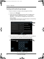
Sending and broadcasting messages
To send or broadcast a message or safety message, do as follows:
1. Tap the icon for Messages.
2. Select which type of message you want to send. A message can be
addressed to a specific MMSI number (Send.....) or to all listeners
(Broadcast.....). The content of a message can be ordinary text or a
safety message.
Unread messages are indicated as a closed envelope icon. Unread safety
messages pop up on the screen on arrival.
1
2
Figure 27: Message types
3. Tap the address field and enter the MMSI number of the ship using the
on-screen keypad (not applicable for broadcasting messages).
3
4
Figure 28: Entering MMSI number
34
To work with messages
98-135323.book Page 35 Wednesday, March 12, 2014 3:59 PM
22222
Chapter 2: Operation
4. Tap Next and enter the message text using the on-screen keyboard.
5. Tap Done or the symbol in the lower left corner to collapse the
keyboard.
Operation
5
5
Figure 29: Writing a message
6. Tap Send to send the message. The message will be shown in the list of
messages sent and received.
6
Figure 30: Sending a message
To work with messages
35
98-135323.book Page 36 Wednesday, March 12, 2014 3:59 PM
Chapter 2: Operation
Figure 31: List of messages
A message sent by the SAILOR 6282 AIS Transponder can have one of the
following states:
•
Sending – The message is under transmission.
•
Sent – The message has been sent completely.
•
Delivered – The message is confirmed delivered to the receiving AIS but
not necessarily read.
Viewing and replying to messages
If there are unread messages, icons appear in the bottom bar:
36
•
Envelope with an exclamation mark: Unread safety-related messages 12
and 14
•
Envelope without exclamation mark: Unread other messages
To work with messages
98-135323.book Page 37 Wednesday, March 12, 2014 3:59 PM
22222
•
White envelopes: New messages have arrived since this was checked
the last time.
New
messages
have arrived.
No new
messages
since last look.
Figure 32: Icons for new messages
1. Tap the icon for unread messages to display the list of unread messages.
Figure 33: Viewing messages
If the received message is longer than one line in the display, the
message is automatically split up into several lines.
To work with messages
37
Operation
Chapter 2: Operation
98-135323.book Page 38 Wednesday, March 12, 2014 3:59 PM
Chapter 2: Operation
2. Tap the message you want to read. The message opens and you can
directly enter text and send a reply.
Figure 34: Replying to a message
When all messages are read, there is no envelope icon in the bottom
bar.
Deleting messages
The latest 20 Safety Related Messages cannot be deleted. All other
messages are deleted when the SAILOR 6282 AIS Transponder is restarted
(power cycle).
38
To work with messages
98-135323.book Page 39 Wednesday, March 12, 2014 3:59 PM
22222
Alarms and notifications
If an alarm is reported from the SAILOR 6282 AIS Transponder a flashing
red triangle appears in the bottom bar of the SAILOR 6004 Control Panel
display:
•
Flashing, bright red triangle: Unacknowledged alarm(s).
•
Faded red triangle: Acknowledged alarm(s).
To acknowledge an alarm do as follows:
1. Tap the flashing, bright red triangle to display the list with active alarms.
2. Tap the alarm to acknowledge the alarm.
2
1
Figure 35: Active alarms
When all active alarms are acknowledged the bright red triangle turns into a
faded red triangle.
Internal hardware errors in the SAILOR 6282 AIS Transponder are reported
as Rx channel malfunction alarm messages. See Table 9 on page 41 for
further details.
Alarms and notifications
39
Operation
Chapter 2: Operation
98-135323.book Page 40 Wednesday, March 12, 2014 3:59 PM
Chapter 2: Operation
Alarms without time stamp
If the SAILOR 6004 Control Panel cannot retrieve the time for an alarm
from the SAILOR 6282 AIS Transponder, this is marked by adding (CPT) to
the alarm title. See the example in the following figure.
Figure 2-36: Active alarms, no time stamp from SAILOR 6282 AIS
Transponder (example)
40
Alarms and notifications
98-135323.book Page 41 Wednesday, March 12, 2014 3:59 PM
22222
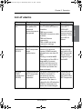
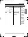
List of alarms
Alarm
Consequence
Reason
Remedy
Connection
lost
AIS list is empty,
the padlock for
password
protection cannot
be opened.
Someone has logged into
the TT-6282A AIS Service
Interface.
After logout
from the TT6282A AIS
Service Interface
resumes normal
operation. Allow
up to 40 s to
reboot.
Tx
malfunction
(ID 001)
The SAILOR 6282
AIS Transponder
stops
transmission.
The AIS is not able to
transmit for technical
reasons (VSWR exceeds
allowed ratio, see alarm ID
002)
Missing or invalid MMSI
The integrity of the VDL is
degraded by incorrect
transmitter behaviour for
instance in case of the Tx
shutdown procedure has
been activated.
Check the VHF
antenna, plugs,
and cable to the
AIS Transponder.
Check correct
programming of
the MMSI.
Antenna
VSWR
exceeds limit
(ID 002)
The SAILOR 6282
AIS Transponder
continues
operation.
For every transmission, the
VSWR is checked. If it
exceeds the warning
threshold, this alarm is
generated. The alarm is
cleared by the AIS when the
VSWR is measured to be
below the threshold again.
Check the VHF
antenna, plugs,
and cable to the
AIS Transponder.
TRX has no power
TRX-MKD connection cable
is defect
TRX lost Ethernet
connection
TRX or MKD use wrong
connection settings.
Table 9: AIS Alarms
List of alarms
41
Operation
Chapter 2: Operation
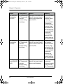
98-135323.book Page 42 Wednesday, March 12, 2014 3:59 PM
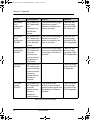
Chapter 2: Operation
Alarm
Consequence
Reason
Remedy
Rx channel
AIS 1
malfunction
(ID 003)
The SAILOR 6282
AIS Transponder
stops
transmission on
the affected
channel.
If continuous monitoring of
the receiver channel 1
shows inconsistency, this
alarm is activated.
Check the VHF
antenna, plugs,
and cable to the
AIS transceiver.
Rx channel
AIS 2
malfunction
(ID 004)
The SAILOR 6282
AIS Transponder
stops transmitting
on the affected
channel.
If continuous monitoring of
the receiver channel 2
shows inconsistency, this
alarm is activated.
Check the VHF
antenna, plugs,
and cable to the
AIS Transponder.
Rx channel 70
malfunction
(ID 005)
The SAILOR 6282
AIS Transponder
continues
operation, but
external channel
management is
not possible.
If continuous monitoring of
the receiver channels shows
inconsistency, this alarm is
activated.
Check the VHF
antenna, plugs,
and cable to the
AIS Transponder.
Check the power
supply to the AIS
Transponder.
General failure The SAILOR 6282
(ID 006)
AIS Transponder
stops functioning.
In case of severe
software or
hardware failure,
this alarm is
activated.
UTC sync
invalid
(ID 007)
The SAILOR 6282
AIS Transponder
continues
operation using
indirect or
semaphore
synchronization.
If the internal GNSS
receiver cannot receive a
synchronization signal from
the satellites, this alarm is
activated.
Table 9: AIS Alarms (Continued)
42
List of alarms
Check the GNSS
antenna, plugs,
and cable to the
AIS Transponder.
98-135323.book Page 43 Wednesday, March 12, 2014 3:59 PM
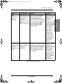
22222
Alarm
Consequence
Reason
Remedy
MKD
Connection
lost
(ID 008)
The SAILOR 6282
AIS Transponder
continues
operation with
DTE set to 1, the
MKD is not active.
This alarm is activated by
the system, if the AIS
Transponder does not
receive heartbeat messages
from at least one minimum
keyboard display (MKD)
unit (e.g. SAILOR 6004
Control Panel).
Check the power
supplies, cabling,
Ethernet
connection
between the AIS
Transponder and
the SAILOR 6004
Control Panel.
Restart both
units: SAILOR
6282 AIS
Transponder:
remove and
connect power,
SAILOR 6004
Control Panel:
use on/off
button.
Internal /
external GNSS
position
mismatch (ID
009)
The SAILOR 6282
AIS Transponder
continues
operation.
This alarm is activated when
the distance between the
external and internal GNSS
position remains >100 m
for an interval longer than
15 minutes.
Check the NMEA
connection
between external
GNSS receiver
and the AIS
Transponder.
Check as well the
GNSS antenna,
plugs, and cable
to the AIS
Transponder.
Table 9: AIS Alarms (Continued)
List of alarms
43
Operation
Chapter 2: Operation
98-135323.book Page 44 Wednesday, March 12, 2014 3:59 PM
Chapter 2: Operation
Alarm
Consequence
Reason
Remedy
NavStatus
incorrect
(ID 010)
The SAILOR 6282
AIS Transponder
continues
operation.
This alarm is activated if a
mismatch exists between
the sensor input and the
Voyage settings status. E.g.
when the status is set by
the operator to At Anchor
and the ship is moving
faster than 3 kn, this alarm
is activated.
Enter the AIS
Application on
the SAILOR 6004
Control Panel
and set Status in
Settings >
Voyage to the
correct state
according to the
ship’s current
movement.
Heading
sensor offset
(ID 011)
The SAILOR 6282
AIS Transponder
continues
operation.
This alarm is activated when
SOG is greater than 5 kn and
the difference between
COG and HDT is greater
than 45° for 5 min.
Check the
heading sensor
and its NMEA
connection to
the AIS
Transponder.
Active AISSART
(ID 014)
The SAILOR 6282
AIS Transponder
continues
operation.
This alarm is activated when
the SAILOR 6282 AIS
Transponder receives a
position report from an AIS
search and rescue
transponder (SART). The
AIS SART indicates the
position of persons in
distress. It is displayed on
the first line in the AIS list
view on the SAILOR 6004
Control Panel.
Table 9: AIS Alarms (Continued)
44
List of alarms
98-135323.book Page 45 Wednesday, March 12, 2014 3:59 PM
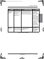
22222
Alarm
Consequence
Reason
External EPFS
lost
(ID 025)
The SAILOR 6282 The alarm is activated if the
AIS Transponder external electronic position
continues
fixing system (EPFS) is lost.
operation, based
on the internal
GNSS.
Check the NMEA
connection
between the
external GNSS
and the AIS
Transponder.
No position
sensor in use
(ID 026)
The SAILOR 6282
AIS Transponder
continues
operation.
Check the GNSS
antenna, plugs,
and cable to the
AIS. Check the
NMEA
connections
between the
external GNSS
and the AIS
Transponder.
Check the status
of the external
GNSS at its own
control panel.
Check that the
GNSS antennas
are not covered
and are free to
receive satellite
signals.
The alarm is activated in
case none of the GNSS
connected to the AIS
Transponder provide valid
position data to the AIS
Transponder.
Remedy
Table 9: AIS Alarms (Continued)
List of alarms
45
Operation
Chapter 2: Operation
98-135323.book Page 46 Wednesday, March 12, 2014 3:59 PM
Chapter 2: Operation
Alarm
Consequence
Reason
Remedy
No valid SOG
information
(ID 029)
The SAILOR 6282
AIS Transponder
continues
operation using
default data.
This alarm is activated when
none of the sensor inputs
reports a valid speed over
ground (SOG).
Check the NMEA
connection
between speed
measuring
device and AIS
Transponder;
check the GNSS
antenna, plugs,
and cable to the
AIS Transponder;
check the NMEA
connection
between the
external GNSS
receiver and the
AIS Transponder.
No valid COG
information
(ID 030)
The SAILOR 6282
AIS Transponder
continues
operation using
default data.
This alarm is activated when
none of the sensor inputs
reports a valid course over
ground (COG).
In order to solve
the problem,
check the GNSS
antenna, plugs,
and cable to the
AIS Transponder;
check the NMEA
connection
between the
external GNSS
receiver and the
AIS Transponder.
Heading
The SAILOR 6282 This alarm is activated when
lost/invalid (ID AIS Transponder none of the sensor inputs
reports a valid heading.
032)
continues
operation using
default data.
Check the NMEA
connection
between heading
sensor and the
AIS Transponder.
Table 9: AIS Alarms (Continued)
46
List of alarms
98-135323.book Page 47 Wednesday, March 12, 2014 3:59 PM
22222
Alarm
Consequence
Reason
Remedy
No valid ROT
information
(ID 035)
The SAILOR 6282
AIS Transponder
continues
operation using
default data.
This alarm is issued if the
rate of turn (ROT) cannot be
determined from sensor
data or internal calculations.
Check the NMEA
connection
between ROT
sensor and AIS
transceiver;
check the GNSS
antenna, plugs,
and cable to the
AIS transceiver;
check the NMEA
connection
between the
external GNSS
receiver and the
AIS Transponder.
TX Silent
Mode Active
The SAILOR 6282 This alarm is activated when The alarm is
AIS Transponder the Silent Mode is
cleared when the
does not transmit. selected.
Silent Mode is
deselected.
Table 9: AIS Alarms (Continued)
List of alarms
47
Operation
Chapter 2: Operation
98-135323.book Page 48 Wednesday, March 12, 2014 3:59 PM
Chapter 2: Operation
48
List of alarms
98-135323.book Page 49 Wednesday, March 12, 2014 3:59 PM
33333
Chapter 3
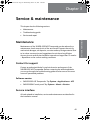
Service & maintenance
This chapter has the following sections:
•
Maintenance
•
Troubleshooting guide
•
Service and repair
Maintenance
Maintenance of the SAILOR 6282 AIS Transponder can be reduced to a
maintenance check at each visit of the service staff. Inspect the unit for
mechanical damages, salt deposits, corrosion and any foreign material. Due
to its robust construction and ruggedness the unit has a long lifetime.
Anyway it must carefully be checked at intervals not longer than 12 months
– dependent on the current working conditions.
Contact for support
Contact an authorized dealer for technical service and support of the
SAILOR 6282 AIS Transponder. Before contacting the authorized dealer
you can go through the troubleshooting guide to solve some of the most
common operational problems.
Software version
•
SAILOR 6282 AIS Transponder: Tap System > Applications > AIS
•
SAILOR 6004 Control panel: Tap System > About > Version
Service interface
All tasks related to installation, service and maintenance are described in
the installation manual.
49
Service & maintenance
3
Troubleshooting.fm Page 50 Thursday, March 27, 2014 2:30 PM
Chapter 3: Service & maintenance
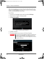
Only a service engineer can access the Service Interface directly from the
display of the SAILOR 6004 Control Panel. This is useful for software update
directly via the SAILOR 6004 Control Panel.
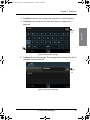
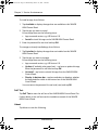
Do as follows:
1. From the list of messages, tap the menu icon and then Settings.
2. Tap the menu icon again, and swipe upwards.
3. Tap Service Interface.
Figure 37: Access the Service Interface
4. Tap Yes to continue.
5. The service engineer can now log in to the Service Interface.
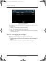
Important
As long as the service engineer is logged into the Service
Interface, the SAILOR 6282 AIS Transponder does not
receive messages. The Control Panel application shows a
Connection lost error.
Figure 38: Login page of the Service Interface
50
Maintenance
98-135323.book Page 51 Wednesday, March 12, 2014 3:59 PM
33333
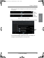
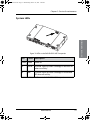
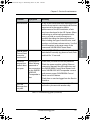
System LEDs
Service & maintenance
Chapter 3: Service & maintenance
Figure 39: LEDs on the SAILOR 6282 AIS Transponder
LED
Colour Description
Power Green
Power on.
Rx
Yellow
Rx mode. Lights up when a message is received. Off
when no activity.
Tx
Red
Tx mode. Lights up when a message is transmitted.
Off when no activity.
Table 10: LEDs on the SAILOR 6282 AIS Transponder
Maintenance
51
98-135323.book Page 52 Wednesday, March 12, 2014 3:59 PM
Chapter 3: Service & maintenance
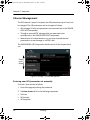
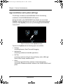
App installation and system settings
The AIS app is installed in the SAILOR 6004 Control Panel during
installation of the SAILOR 6280/6281 AIS System.
Having switched on the SAILOR 6004 Control Panel, an icon named
System is always displayed, plus the icon(s) of the applications that are
installed. Under System you can set up and manage the SAILOR 6004
Control Panel.
Figure 40: Screen to enter System (example)
Tap the icon System and the following topics are available:
52
•
Settings
containing Network, Date/Time and Debugging.
•
Applications
containing installed and available applications.
•
Self Test
containing a self test of Touch, Controls Display, Audio, USB, Light
Sensor, Alarm Output, NMEA and LAN.
•
About
containing Legal information, software versions and network
information (IP address and MAC address of the SAILOR 6004 Control
panel).
Maintenance
98-135323.book Page 53 Wednesday, March 12, 2014 3:59 PM
33333
Chapter 3: Service & maintenance
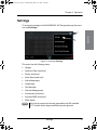
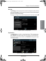
Settings
Tap Settings to enter the section for network configuration, date and time
setting and debugging. Tap the section you want to work with and explore
the touch screen for each setting.
Service & maintenance
To change a setting you must enter the password for user level and tap OK.
Figure 41: System - Settings, Display
Applications
Tap Applications to install or uninstall applications. This section has two
tabs: Available, showing the apps that are available to the SAILOR 6004
Control Panel on the current network, and Installed, showing which apps
are already installed.
Figure 42: System – Applications (example)
Maintenance
53
98-135323.book Page 54 Wednesday, March 12, 2014 3:59 PM
Chapter 3: Service & maintenance
To install an app, do as follows:
1. Tap Available to display the apps that are available to this SAILOR
6004 Control Panel.
2. Tap the app you want to install.
For each app there are the following items::
•
App name and version, e.g. AIS Version 2.0.
•
Install to install this app on the SAILOR 6004 Control Panel.
3. Enter the password for user level and tap OK.
To manage an already installed app, do as follows:
1. Tap Installed to display the apps that are installed on this SAILOR
6004 Control Panel.
2. Tap the app you want to manage.
For each app there are the following items::
•
App name and version, e.g. AIS Version 2.0.
•
Update (if available, else grayed out) – tap here to update this app.
Enter the password for user level and tap OK.
•
Uninstall – tap here to uninstall this app from the SAILOR 6004
Control Panel.
•
Display in bottom bar – tap here and select or deselect whether
the app should be visible in the bottom bar of the SAILOR 6004
Control Panel.
You must enter the password for user level (user) and tap OK.
Self Test
Tap Self Test to start the self test of the SAILOR 6004 Control Panel. For
further details on the self test see the installation manual of the SAILOR
6004 Control Panel.
About
Tap About to view the following:
54
Maintenance
98-135323.book Page 55 Wednesday, March 12, 2014 3:59 PM
33333
Chapter 3: Service & maintenance
Legal with legal and copyright information, open source licences, etc.
•
Version with various software versions and serial number of the
SAILOR 6004 Control Panel.
•
Network with IP address and MAC address of the SAILOR 6004 Control
Panel.
Service & maintenance
•
Maintenance
55
98-135323.book Page 56 Wednesday, March 12, 2014 3:59 PM
Chapter 3: Service & maintenance
Troubleshooting guide
Problem
Symptom
Remedy
The SAILOR
6282 AIS
Transponder
will not turn
on.
Green LED on
SAILOR 6282
AIS
Transponder is
off.
If the power cable is connected directly to the
SAILOR 6282 AIS Transponder then check that
the white wire in the power cable is connected
to the black wire (-DC). If power to SAILOR
6282 AIS Transponder is connected via the
connection board then check the jumper W8 is
placed in position AIS ON. For further details
see the Installation manual.
No communication
No flashing
yellow or red
LED on AIS
transponder
Check if a valid MMSI has been entered. For
further details see the installation manual.
No GPS
No signal from
GPS. Position
requested.
Check the antenna cable to the GPS.
Missing MMSI
When powering up the SAILOR 6282 AIS
Transponder for the first time after leaving the
factory there is no MMSI stored in the SAILOR
6282 AIS Transponder. Enter a valid MMSI to
operate the SAILOR 6282 AIS Transponder. For
further details see the Installation manual.
Wrong MMSI
If a wrong MMSI number has been entered
and stored, or if there is a requirement to
change it, contact your authorized dealer.
Table 11: Troubleshooting guide
56
Troubleshooting guide
98-135323.book Page 57 Wednesday, March 12, 2014 3:59 PM
33333
Problem
Symptom
Remedy
Device failure
If any of the checks and tests described in this
section do not assist in resolving the difficulties
experienced in the operation and/or
performance of the AIS installation, a fault
may have developed in the AIS System. When
contacting an authorized representative be
sure to provide as much information as
possible describing the observed behaviour also including the type of the AIS units, serial
number, and software release version. You find
this information in the setup menu of the
connected SAILOR 6004 Control Panel.
SAILOR 6004
Control Panel
cannot be
switched off.
If the SAILOR 6004 Control Panel cannot be
switched off normally (e.g. due to a fault): Push
and hold for 12 seconds.
Password
entered, but
padlock does
not open
The Test
Message does
not pass.
Authorization
failed. Wrong
password or
the connection
to the SAILOR
6282 AIS
Transponder is
lost
Check that you enter the correct password.
Check the power supplies, cabling, Ethernet
connection between the AIS transceiver and
the SAILOR 6004 Control Panel. Restart both
units: SAILOR 6282 AIS Transponder: remove
and connect power, SAILOR 6004 Control
Panel: use on/off button.
Check that no one has logged into the Service
Interface.
If you do not receive an answer within 30
seconds try the test with another ship.
Table 11: Troubleshooting guide (Continued)
Troubleshooting guide
57
Service & maintenance
Chapter 3: Service & maintenance
98-135323.book Page 58 Wednesday, March 12, 2014 3:59 PM
Chapter 3: Service & maintenance
Service and repair
Should your Cobham SATCOM product fail, please contact your dealer or
installer, or the nearest Cobham SATCOM partner. You will find the partner
details on www.cobham.com/satcom where you also find the Cobham
SATCOM Self Service Center web-portal, which may help you solve the
problem.
Your dealer, installer or Cobham SATCOM partner will assist you whether
the need is user training, technical support, arranging on-site repair or
sending the product for repair.
Your dealer, installer or Cobham SATCOM partner will also take care of any
warranty issue.
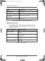
Applicable SAILOR and part numbers
This installation manual is for the SAILOR 6280/6281 AIS System and is
applicable to the part numbers below:
Part number
Description
406282A
SAILOR 6282 AIS Transponder
406004A
SAILOR 6004 Control Panel
406285A
SAILOR 6285 GPS Antenna - Active
406283A
SAILOR 6283 AIS Connection Box and Wall Tray
Table 12: Part numbers for the SAILOR 6280/6281 AIS System
58
Service and repair
98-135323.book Page 59 Wednesday, March 12, 2014 3:59 PM
33333
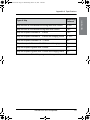
Accessories
The following accessories are included in the delivery:
Part number
Description accessories
37-130130
DC Power cable for SAILOR 6282 AIS
Transponder and SAILOR 6004 Control Panel
37-135955
SUB-D50 cable, 1 m
37-207073-000
RJ45 Cat5e STP LAN cable, 5 m
41-135855
GPS Antenna bracket
67-135974
Pilot plug
Service & maintenance
Chapter 3: Service & maintenance
Table 13: Part numbers for accessories
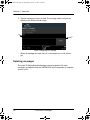
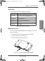
Replacing the fuse
One fuse is installed in the SAILOR 6282 AIS Transponder. If this fuse is
blown, do as follows:
1. Track down why the fuse was blown and solve the problem.
2. Take out the old fuse. Use the fuse puller.
3. Insert the new fuse. The fuse rating is 5 A T.
Figure 43: 5 A T fuse in the SAILOR 6282 AIS Transponder
Service and repair
59
98-135323.book Page 60 Wednesday, March 12, 2014 3:59 PM
Chapter 3: Service & maintenance
Repacking for shipment
Should you need to send the product for repair, please read the below
information before packing the product.
The shipping carton has been carefully designed to protect the SAILOR
6282 AIS Transponder and its accessories during shipment. This carton and
its associated packing material should be used when repacking for
shipment. Attach a tag indicating the type of service required, return
address, part number and full serial number. Mark the carton FRAGILE to
ensure careful handling.
Note
Correct shipment is the customer’s own responsibility.
If the original shipping carton is not available, the following general
instructions should be used for repacking with commercially available
material.
1. Wrap the defective unit in heavy paper or plastic. Attach a tag
indicating the type of service required, return address, part number and
full serial number.
2. Use a strong shipping container, e.g. a double walled carton.
3. Protect the front- and rear panel with cardboard and insert a layer of
shock-absorbing material between all surfaces of the equipment and the
sides of the container.
4. Seal the shipping container securely.
5. Mark the shipping container FRAGILE to ensure careful handling.
Failure to do so may invalidate the warranty.
60
Service and repair
98-135323.book Page 61 Wednesday, March 12, 2014 3:59 PM
AAAAA
Specifications
A
SAILOR 6282 AIS Transponder
Item
Specification
Weight
1.15 kg
Dimensions (L x W x H)
160 x 270 x 42 mm
Equipment class
Protected, according to IEC 60945
Input voltage
10.8 VDC to 31.2 VDC
Power consumption
12 W (0.5 A @24 VDC input voltage)
Heat dissipation
10 W
Temperature
-15 °C to +55 °C (Operational)
-30 °C to +70 °C (Storage)
Compass Safe Distance
55 cm (standard magnetic compass)
45 cm (Emergency magnetic compass)
Receivers
156.025 - 162.025 MHz (TDMA)
156.525 MHz (Channel 70, DSC)
Channel bandwidth
25 kHz
RF Output Power
High: 12.5 W
Low: 1 W
Low power forced control (gas alarm): 1 W
Frequency
156.025 - 162.025 MHz
VHF connector
TNC female
Table 14: SAILOR 6282 AIS Transponder specifications
61
Specifications
Appendix A
98-135323.book Page 62 Wednesday, March 12, 2014 3:59 PM
Appendix A: Specifications
Item
Specification
GPS connector
TNC female
VHF and GPS cable
RG214 or better
Connection to SAILOR 6004
Control Panel
LAN (LWE IEC 61162-450)
Connections to sensors and PI 50 pin sub-D
Table 14: SAILOR 6282 AIS Transponder specifications
Reporting Intervals
The SAILOR 6282 AIS Transponder is transmitting in different intervals
depending of the dynamic input data as speed and turn. The reporting
intervals are as follows:
Type of information
Reporting interval
Static Information
Every 6 min. or when data has been amended and
on request.
Dynamic Information
Depending on speed and course alteration, see
the table below.
Voyage related information
Every 6 min. or when data has been amended and
on request.
Safety related message
As required.
Table 15: Reporting intervals
62
SAILOR 6282 AIS Transponder
98-135323.book Page 63 Wednesday, March 12, 2014 3:59 PM
AAAAA
Type of ship
Reporting
Interval
Ship at anchor or moored and not moving faster than 3 knots
3 min
Ship at anchor or moored and moving faster than 3 knots
10 s
Ship with a speed of between 0 - 14 knots
10 s
Ship with a speed of between 0 - 14 knots and changing course
3 1/3 s
Ship with a speed of between 14 - 23 knots
6s
Ship with a speed of between 14 - 23 knots and changing course
2s
Ship with a speed of greater than 23 knots
2s
Ship with a speed of greater than 23 knots and changing course
2s
Table 16: Reporting intervals for types of ship
SAILOR 6282 AIS Transponder
63
Specifications
Appendix A: Specifications
98-135323.book Page 64 Wednesday, March 12, 2014 3:59 PM
Appendix A: Specifications
SAILOR 6285 GPS Antenna - Active
Item
Specification
Dimensions
Ø: 91 mm, H: 77.5 mm
Weight
0.15 kg
Mounting
Bracket mount on pipe, thread 1” x 14 TPI
Equipment class
Exposed, according to IEC 60945
Antenna type
Active patch antenna
Frequency
1570 to 1608 MHz
Impedance
Nominal 50 Ohm
Polarization
Circular right-hand
Coverage
Hemispherical
Selectivity
45 dB down at center ±25 MHz
Gain
28 dB
Supply voltage
5 ±1 VDC
Current consumption
Approx. 30 mA
Connector
TNC female
Cable
RG214 recommended
Operating temperature -40 °C to +55 °C
Storage temperature
-40 °C to +70 °C
Table 17: SAILOR 6285 GPS Antenna - Active specifications
64
SAILOR 6285 GPS Antenna - Active
98-135323.book Page 65 Wednesday, March 12, 2014 3:59 PM
AAAAA
SAILOR 6283 AIS Connection Box and Wall
Tray
Item
Specification
Weight without SAILOR 6282 AIS Transponder
2.15 kg
Weight with SAILOR 6282 AIS Transponder mounted 3.30 kg
Dimensions (L x W x H)
340 x 310 x 55 mm
Equipment class
Protected, according to
IEC 60945
Compass Safe Distance
55 cm (standard
magnetic compass)
45 cm (Emergency
magnetic compass)
Table 18: SAILOR 6283 AIS Connection Box and Wall Tray specifications
SAILOR 6004 Control Panel
Item
Specifications
Mounting method
Flush mount or bracket
Voltage
10.8 to 31.2 VDC
Power consumption
Typical: 18 W active
Peak: 42 W
3.15 A internal fuse (non-serviceable)
Audio input
Up to 6 W in 8 Ohm
Interfaces
2 x Ethernet (10/100 Mbit/s)
Accessories connector
Auxiliary connector
Table 19: SAILOR 6004 Control Panel specifications
SAILOR 6283 AIS Connection Box and Wall Tray
65
Specifications
Appendix A: Specifications
98-135323.book Page 66 Wednesday, March 12, 2014 3:59 PM
Appendix A: Specifications
Item
Specifications
Compliance
•
IEC 60945
•
IEC 60950-1
IP rating
IP54a
Ambient temperature
-15 °C to 55 °C
Storage temperature
-30 °C to 80 °C
Compass safe distance 0.6 m
Dimensions W x H x D
191 mm x 145 mm x 61 mm (without mounting
bracket)
Weight
1.1 kg (1.25 kg with mounting bracket)
Table 19: SAILOR 6004 Control Panel specifications (Continued)
a. Estimated.
66
SAILOR 6004 Control Panel
98-135323.book Page 67 Wednesday, March 12, 2014 3:59 PM
BBBBB
Appendix B
NMEA sentences
B
NMEA sentences
Sentences defined in IEC 61993-2
:
IEC 61993-2 sentence
Support
IEC 61162-1 sensor sentences
DTM, GBS, GGA, GNS, HDT, RMC,
ROT, THS, VBW, VTG
AIS High-speed input data and
formats
ABM, ACA, AIR, BBM, EPV, HBT, LRF,
SPW, SSD, VSD
AIS high speed output data and
formats
ABK, ACA, EPV, LRF, NAK, VER, SSD,
TXT, VDM, VDO, VSD,
AIS Long-Range communications
input data and formats
LRI, LRF
LR output data formats
LR1, LR2, LR3, LRF, LRI
Optional PI port sentences
EPV, SPW, TRL
Transmission of binary Message
25 and 26
ABM, BBM, ABK
Table 20: Supported NMEA sentences IEC 61993-2
Sentences defined by Cobham SATCOM
Proprietary protocol.
•
PIWWIVD
•
PIWWSSD
•
PTHRAOC
•
PTHRROS
•
PTHRSNR
67
98-135323.book Page 68 Wednesday, March 12, 2014 3:59 PM
Appendix B: NMEA sentences
68
Sentences defined by Cobham SATCOM
98-135323.book Page 69 Wednesday, March 12, 2014 3:59 PM
CCCCC
Glossary
Glossary
A
AIS SART
AIS Search And Rescue Transmitters
AIS
Automatic Identification System
C
CCNR
Central Commission for Navigation on the Rhine, an
international organization whose function is to encourage
European prosperity by guaranteeing a high level of security for
navigation of the Rhine and environs.
COG
Course Over Ground
D
DGNSS
Differential Global Navigational Satellite System
DSC
Digital Selective Calling. Primarily intended to initiate ship-toship, ship-to-shore and shore-to-ship radiotelephone and
MF/HF radiotelex calls. Each DSC-equipped ship, shore station
and group is assigned a unique 9-digit Maritime Mobile Service
Identity. DSC distress alerts, which consist of a preformatted
distress message, are used to initiate emergency
communication with ships and rescue coordination centers.
DTE
Data Terminal Equipment
E
ECDIS
Electronic Chart Display and Information System (ECDIS) is a
computer-based navigation information system that complies
with International Maritime Organization (IMO) regulations and
can be used as an alternative to paper nautical charts.
G
GLONASS
GLObal’naya NAvigatsionnaya Sputnikovaya Sistema. Global
Navigation Satellite System in English.
69
Glossary
C
98-135323.book Page 70 Wednesday, March 12, 2014 3:59 PM
Glossary
GNSS
Global Navigational Satellite System
GPL
General Public License
GPL
General Public License, software license, which guarantees
individuals, organizations and companies the freedom to use,
study, share (copy), and modify the software.
GPS
Global Positioning System. A system of satellites, computers,
and receivers that is able to determine the latitude and
longitude of a receiver on Earth by calculating the time
difference for signals from different satellites to reach the
receiver.
H
HDT
HeaDing True
I
IEC
International Electrotechnical Commission. The international
standards and conformity assessment body for all fields of
electrotechnology.
IMO
International Maritime Organization
INS
Integrated Navigation System
IP
Ingress Protection. An international classification system for
the sealing effectiveness of enclosures of electrical equipment
against the intrusion into the equipment of foreign bodies (i.e.
tools, dust, fingers) and moisture. This classification system
uses the letters "IP" followed by two or three digits. An "x" is
used for one of the digits if there is only one class of protection;
e.g. IPX4 which addresses moisture resistance only.
L
LAN
Local Area Network
LGPL
Lesser General Public License
70
98-135323.book Page 71 Wednesday, March 12, 2014 3:59 PM
CCCCC
LWE
LightWeight Ethernet
M
MKD
Minimum Keyboard Display
MMSI
MMSI Maritime Mobile Service Identity. A series of nine digits
which are sent in digital form over a radio frequency channel in
order to uniquely identify ship stations, ship earth stations,
coast stations, coast earth stations, and group calls. These
identities are formed in such a way that the identity or part
thereof can be used by telephone and telex subscribers
connected to the general telecommunications network to call
ships automatically.
MPE
Maximum Permissible Emission
N
NMEA
National Marine Electronics Association (standard). A combined
electrical and data specification for communication between
marine electronic devices such as echo sounder, sonars,
anemometer (wind speed and direction), gyrocompass,
autopilot, GPS receivers and many other types of instruments.
It has been defined by, and is controlled by, the U.S.-based
National Marine Electronics Association.
P
PI
Presentation Interface
R
RAIM
Receiver Autonomous Integrity Monitoring. Integrity check of
the position.
RF
Radio Frequency
ROT
Rate Of Turn
71
Glossary
Glossary
98-135323.book Page 72 Wednesday, March 12, 2014 3:59 PM
Glossary
S
SART
Search And Rescue Transponder
SOG
Speed Over Ground.
SOLAS
(International Convention for the) Safety Of Life At Sea.
Generally regarded as the most important of all international
treaties concerning the safety of merchant ships.
SRM
Safety Related Messages
T
TDMA
Time-Division Multiple Access
TPI
Threads Per Inch
U
UTC
Universal Time, Coordinated. The International Atomic Time
(TAI) with leap seconds added at irregular intervals to
compensate for the Earth’s slowing rotation. Leap seconds are
used to allow UTC to closely track UT1, which is mean solar
time at the Royal Observatory, Greenwich.
V
VDL
VHF Data Link
VHF
Very High Frequency. 30-300 MHz, a "straight-line" signal used
for short-distance terrestrial communication and navigation.
VSWR
Antenna Voltage Standing Wave Ratio
VTS
Vessel Traffic Service, a marine traffic monitoring system
established by harbour or port authorities, similar to air traffic
control for aircraft.
72
98-135323.book Page 73 Wednesday, March 12, 2014 3:59 PM
DDDDD
Index
A
F
accessories, 59
AIS
channel change, 28
introduction, 1
software version, 49
alarm, 39
output, 6
alarms, 41
antenna, combined, 6
app
display in bottom bar, 54
applications, 53
fuse, 65
rating, 59
replace, 59
B
bearing value, 11
Blue sign, 6
bottom bar, 54
display app, 54
brightness, 13
buzzer, 7
C
cargo, 17
change AIS channel, 28
channel management, 28
Com test, 27
compass safe distance, iii, 66
connection box, 6
Control Panel
software version, 49
D
DGNSS, 20
dimensions, 66
dimming function, 13
display
brightness, 13
display in bottom bar, 54
document number
this manual, i
draught, 18
E
ETA, 17
G
gas alarm, 6
GNSS signal level, 30
GPS
no fix, 30
signal level, 30
GPS antenna position
external, 22
internal, 22
I
D
icon in bottom bar, 54
idle screen, 10
sort lists, 13
IEC 61993-2
sentences, 67
IMO number, 21
install app, 53
IP address, 30
Control Panel, 55
Index
Index
L
LED
Power, 51
Rx, 51
Tx, 51
license
software, ii
LO, 12
Long Range, 25
message, read, 25
satellite tracking, 6
low power forced control, 6
LR, 12
M
MAC address
Control Panel, 55
73
98-135323.book Page 74 Wednesday, March 12, 2014 3:59 PM
Index
manual
document number, i
message
SART, 33
unread, 12
MMSI
Missing MMSI, 56
number, 21
wrong MMSI, 56
model numbers, 58
N
night mode, 7, 13
NMEA interface versions, 5
NMEA sentences, 67
Cobham SATCOM, 67
IEC 61993-2, 67
O
open source licences, 55
P
padlock, 16
parameters
set, 15
part numbers, 58
accessories, 59
password, 16
pilot plug, 6
pirat mode, 31
Power LED, 51
presentation interfaces, 6
SART messages, 33
self test, 54
sensor inputs, 6
sentences
IEC 61993-2, 67
proprietary, 67
settings, 15
ship details, 14
silent mode, 12, 31
software
uninstall, 54
software license, ii
software version
AIS, 49
Control Panel, 49
SOG/COG
internal or external, 20
sorting lists in idle view, 13
status, 20
T
ThraneLINK, 5
time, 12
troubleshooting, 56
Tx LED, 51
TX off, 12
TXT, 12
U
uninstall, 54
unread messages, 12
V
R
VTS tool, 2
radar, 3
range, 11
reporting interval, 62
RF exposure, iii
ROT, 6
Rx LED, 51
W
S
safety distance, iii
74
warranty, iii, 58
waterproof, iii
98-135323-C
www.cobham.com/satcom