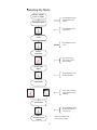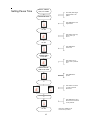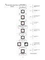
1
PHASE 7
DMC
USER’S MANUAL
American Dryer Corporation
88 Currant Road
Fall River, MA 02720-4781
Telephone: (508) 678-9000 / Fax: (508) 678-9447
E-mail: [email protected]
www.amdry.com
080102JMORALES/wmarelli
ADC Part No. 113399
Retain This Manual In A Safe Place
For Future Reference
Please read this manual carefully to thoroughly familiarize yourself with the Phase 7 Dual Coin
Microprocessor computer system features, operational instructions, and programming characteristics.
This manual contains important information on how to employ ALL the features of your new ADC
dryer in the safest and most economical way.
American Dryer Corporation products embody advanced concepts in engineering, design, and safety.
If this product is properly maintained, it will provide many years of safe, efficient, and trouble-free
operation.
We have tried to make this manual as complete as possible and hope you will find it useful. ADC
reserves the right to make changes from time to time, without notice or obligation, in prices, specifications,
colors, and material, and to change or discontinue models.
“IMPORTANT NOTE TO PURCHASER”
Information must be obtained from your local gas supplier on
the instructions to be followed if the user smells gas. These
instructions must be posted in a prominent location near the dryer.
IMPORTANT
YOU MUST DISCONNECT AND LOCKOUT THE ELECTRIC SUPPLY
AND THE GAS SUPPLY OR THE STEAM SUPPLY BEFORE ANY COVERS
OR GUARDS ARE REMOVED FROM THE MACHINE TO ALLOW ACCESS
FOR CLEANING, ADJUSTING, INSTALLATION, OR TESTING OF ANY
EQUIPMENT PER OSHA (Occupational Safety and Health Administration)
STANDARDS.
FOR YOUR SAFETY
DO NOT STORE OR USE GASOLINE OR OTHER FLAMMABLE
VAPORS AND LIQUIDS IN THE VICINITY OF THIS OR ANY OTHER
APPLIANCE.
DO NOT DRY MOP HEADS IN THE DRYER.
DO NOT USE DRYER IN THE PRESENCE OF DRY CLEANING FUMES.
CAUTION
DRYERS SHOULD NEVER BE LEFT UNATTENDED WHILE IN
OPERATION.
WARNING
CHILDREN SHOULD NOT BE ALLOWED TO PLAY ON OR NEAR
THE DRYERS.
CHILDREN SHOULD BE SUPERVISED IF NEAR DRYER(S) IN
OPERATION.
WARNING
The dryer must never be operated with any of the back guards, outer tops,
or service panels removed. PERSONAL INJURY OR FIRE COULD
RESULT.
WARNING
DRYER MUST NEVER BE OPERATED WITHOUT THE LINT
FILTER OR SCREEN IN PLACE, EVEN IF AN EXTERNAL LINT
COLLECTION SYSTEM IS USED.
IMPORTANT
PLEASE OBSERVE ALL SAFETY PRECAUTIONS displayed on the
equipment and specified in the installation manual included with the dryer.
Dryers must not be installed or stored in an area where it will be exposed to
water or weather.
The wiring diagram for the dryer is located in the front electrical control box area.
WARNING
Power must be disabled prior to changing S.A.F.E. System temperature probe!!
The S.A.F.E. System will be activated if probe is removed while dryer is powered
on.
NOTE
If power to the dryer is off, the S.A.F.E. System is disabled.
Table of Contents
SECTION I
INTRODUCTION ....................................................................................................... 3
SECTION II
FEATURES .................................................................................................................. 4
A.
B.
C.
D.
E.
F.
G.
H.
I.
J.
K.
L.
M.
N.
O.
P.
Q.
R.
S.
T.
Dependable Microprocessor Solid State Integrated Circuitry .................................................. 4
Sensor Activated Fire Extinguishing (S.A.F.E.) System .......................................................... 4
Program Changes are Easily Made at the Keyboard (Touch Pad) ............................................ 4
Temperature Selections ............................................................................................................. 4
Cool Down ................................................................................................................................ 4
Liquid Crystal Display (L.C.D.) ............................................................................................... 4
Anti-Wrinkle Program .............................................................................................................. 4
Diagnostics ............................................................................................................................... 4
Audio Alert Signal .................................................................................................................... 4
Temperature Conversion Status ................................................................................................ 4
High-Temperature Protection ................................................................................................... 4
RPM .......................................................................................................................................... 5
Clean Lint ................................................................................................................................. 5
Language Selection ................................................................................................................... 5
Model Selection ........................................................................................................................ 5
Keyboard (Touch Pad) Symbols ............................................................................................... 5
Currency Selection.................................................................................................................... 5
Dry Mode .................................................................................................................................. 5
Vending Safeguard .................................................................................................................... 5
Credit Retention ........................................................................................................................ 5
SECTION III
OPERATING INSTRUCTIONS ................................................................................ 6
A. Coin Mode
Hot Keys-Remaining Credit, Temp, RPM ................................................................................ 6
B. Free Mode
Hot Keys-Remaining Credit, Temp, RPM ................................................................................ 6
C. Pause Mode .............................................................................................................................. 7
D. RPM .......................................................................................................................................... 7
E. Clearing Credit ......................................................................................................................... 7
F. Accessing Coin Vault ................................................................................................................ 7
SECTION IV
L.C.D. OPERATING MESSAGES ............................................................................ 8
A. Coin Mode ................................................................................................................................ 8
B. Free Mode ................................................................................................................................. 9
C. Messages Common to Coin and Free Mode ............................................................................. 9
SECTION V
PROGRAM SELECTIONS (PL01-PL14) .............................................................. 10
PL01 Select Language .................................................................................................................. 10
PL01 Select Currency ................................................................................................................... 10
PL01 Select Model ....................................................................................................................... 10
PL01 Select Temp Scale ............................................................................................................... 10
PL01 Select Buzzer Mode ............................................................................................................ 10
PL01 Select Dry Mode ................................................................................................................. 11
PL01 Select Vending Safeguard ................................................................................................... 11
PL01 Select Vending Mode .......................................................................................................... 11
PL01 Select Rotation Sensor Mode .............................................................................................. 14
PL02, PL04, PL06 High, Low, Medium Cycle Dry Temp. ........................................................... 14
PL03, PL05, PL07 High, Low, Medium Cycle Cool Time ........................................................... 15
PL08, PL09 Left/Right Coin Denomination ................................................................................. 15
PL10 Time for Amount to Start .................................................................................................... 15
PL11 Amount to Start ................................................................................................................... 15
PL12 Amount for Additional Time ............................................................................................... 16
PL13 Prepurge Time ..................................................................................................................... 16
PL13 DSI Purge Time ................................................................................................................... 16
PL13 DSI Proof Time ................................................................................................................... 16
PL13 Buzz Time ........................................................................................................................... 16
PL13 Pause Time .......................................................................................................................... 16
PL14 Lint Cleaning Frequency ..................................................................................................... 16
PL14 Retry Count ......................................................................................................................... 16
PL14 Upper Dryer Faults .............................................................................................................. 17
PL14 Lower Dryer Faults ............................................................................................................. 17
Anti-Wrinkle Program .................................................................................................................. 17
Fire Suppression System (FSS) .................................................................................................... 17
SECTION VI
PROGRAMMING INSTRUCTIONS ..................................................................... 18
A. Introduction to Programming ................................................................................................. 18
B. Program Location Summary ................................................................................................... 19
C. Programming Flowcharts........................................................................................................ 20
D. Flowchart Table of Contents .................................................................................................... 21
SECTION VII
FACTORY PRESETS ............................................................................................... 56
SECTION VIII
PHASE 7 COIN SYSTEM DIAGNOSTICS ........................................................... 57
A.
B.
C.
D.
Diagnostic L.C.D. Fault Messages ......................................................................................... 57
FSS Diagnostic Messages ....................................................................................................... 60
Input/Output (I/O) Board Light Emitting Diode (L.E.D.) Indicators ..................................... 61
Keyboard (Touch Pad) Layout ................................................................................................ 63
SECTION I
INTRODUCTION
Phase 7 Dual Coin Microprocessor Drying System
American Dryer Corporation’s Phase 7 Dual Coin Microprocessor Drying System has been designed with
super performance in mind to provide for better temperature regulation, efficiency, performance, consistency,
and faster drying times.
Utilizing this microprocessor technology, the user simply has to place the load in the dryer, insert credit, and push
one (1) button to start the drying cycle.
The phase 7 dual coin microprocessor provides a very simple user interface, while simultaneously implementing
state-of-the-art technology to ensure safety and performance. The phase 7 dual coin microprocessor controller
constantly monitors the dryer and ALL systems to ensure proper functionality and eliminates ALL guesswork in
the maintenance of the dryer.
3
SECTION II
FEATURES
A. Dependable Microprocessor Solid State Integrated Circuitry - The phase 7 dual coin
microprocessor controller utilizes one (1) microprocessor that monitors and controls two (2) dryer
pockets independently of each other. The dependable microprocessor solid state design of the controller
allows for the elimination of as many moving parts as possible while increasing the reliability and
functionality of the control.
B. Sensor Activated Fire Extinguishing (S.A.F.E.) System - A standard feature, which continually
monitors the basket (tumbler) for fires. In the event of a fire, a water supply to the basket (tumbler) will
suppress the fire. The phase 7 dual coin microprocessor controller (computer) will also notify the user
that a fire has taken place.
C. Program Changes are Easily Made at the Keyboard (Touch Pad) - The phase 7 dual coin
microprocessor controller can be customized by modifying the setting in the Program Menu, which is
easily done via the attached keyboard (touch pad) and no external equipment is necessary.
D. Temperature Selections - Accommodates 3 temperature settings: “HIGH,” “MEDIUM,” and “LOW,”
each programmable to a drying temperature between 100º F (38º C) and 190º F (87º C) for radial
airflow or 100º F (38º C) and 150º F (66º C) for axial airflow.
E. Cool Down - Cool down lowers the temperature in the basket (tumbler) to make the material cool
enough to handle.
F. Liquid Crystal Display (L.C.D.) - The phase 7 dual coin microprocessor controller features a 128 x
64 dots graphic liquid crystal display that has been subdivided into two (2) sections, one (1) section for
the top dryer pocket and one (1) section for the bottom dryer pocket. The phase 7 dual coin
microprocessor controller informs users of cycle status, programs settings, and displays important
diagnostic and fault codes, via the liquid crystal display.
G. Anti-Wrinkle Program - Helps keep items wrinkle-free when they are not removed from the dryer
promptly at the end of the drying and cooling cycles.
H. Diagnostics - The phase 7 dual coin microprocessor controller monitors major circuits, including door
switches, temperature sensors, heat output circuits and more for each dryer pocket individually. This
allows for precise failure messages.
I. Audio Alert Signal - The tone will sound at the end of a complete drying cycle at a 1-second rate for
the duration programmed. It will also sound for any fault conditions at a quarter-second rate for
4-beeps. Finally, there is a 3-beep warning at the beginning of every Anti-Wrinkle On Cycle, and a
continuous rapid pulse is used for the entire duration of S.A.F.E. activation.
J. Temperature Conversion Status - Temperature-related programs can be set in either Fahrenheit
(ºF) or Celsius (ºC). ALL temperatures will automatically convert to the corresponding values (+/- 1º)
when changes are made.
K. High-Temperature Protection - If the phase 7 dual coin microprocessor controller senses that the
temperature in the basket (tumbler) of one of the dryer pockets has exceeded 20º above maximum
setpoint, it will end the drying cycle, and a fault code will be displayed indicating an overheating problem.
4
L. RPM - The phase 7 dual coin microprocessor controller individually monitors the speed of each pocket’s
basket (tumbler) rotation.
M. Clean Lint - The phase 7 dual coin microprocessor controller monitors each dryer pocket separately
and will notify the user when the lint access should be cleaned.
N. Language Selection - Phase 7 dual coin microprocessor controller (computer) has the ability to display
six (6) different languages: English, French, Spanish, Italian, Japanese and Dutch.
O. Model Selection - The phase 7 dual coin microprocessor controller (computer) can be programmed to
be used on six (6) different model dryers, defined by heat type and the quantity of motors.
P. Keyboard (Touch Pad) Symbols -
= “LOW/DOWN” key (scroll down)
= “MEDIUM/ENTER” key
= “HIGH/UP” key (scroll up)
= “PAUSE/CLEAR” key
Q. Currency Selection - The phase 7 dual coin microprocessor controller (computer) can be programmed
to display ALL currency in one of the following seven (7) currency symbols.
USD/ UK Pound/ Euro/ Belgium Franc/ French Franc/ Yen/ Lira
R. Dry Mode - The phase 7 dual coin microprocessor controller (computer) can be programmed to
operate in either coin mode or free dry mode.
S. Vending Safeguard - This feature provides protection against counterfeit coins.
T. Credit Retention - In the event that the phase 7 dual coin microprocessor controller experiences a
power loss, the controller will automatically retain the amount of remaining credit that each pocket had
at the time of the power loss. When power is restored, the phase 7 dual coin microprocessor controller
will prompt the user to select a temp cycle for each pocket that had remaining credit. The time vended
will be based on the remaining credit that was present at the time of the power loss.
NOTE: If credit was inserted into the dryer but was not applied to one of the dryer pockets at the time
of the power loss the credit would be lost.
5
SECTION III
OPERATING INSTRUCTIONS
A. COIN MODE
1. When at least one (1) of the dryer pockets is in the ready state and no cycle is in progress, the liquid crystal
display (LCD) screen will read “Ready, Insert $1.00 to Start”. If both pockets are idle both sections of the
liquid crystal display (LCD) screen will read “Ready, Insert $1.00 to Start”.
2. Insert coin(s). Once the correct “Amount to Start” has been inserted, the pocket will now display “SELECT
TEMP TO START”. If the other pocket was already in a cycle that pocket will display “SELECT TEMP
TO ADD TIME”. If both pockets were idle, both pockets will display “SELECT TEMP TO START”.
3. Select temperature by pressing “HIGH,” “MEDIUM,” or “LOW” on the dryer pocket you wish to start the
cycle in. The cycle will start, and the L.C.D. will display the Dry Cycle selected and the remaining time.
4. The dryer will continue through the drying and cooling cycles until the vended time has expired.
5. Upon completion of drying and cooling cycles the buzzer will sound, and the dryer will go into Anti-Wrinkle
mode for 99 minutes or until the door has been opened.
6. HOT KEYS - When the control is in coin mode, the HOT KEYS are disabled. The HOT KEYS can be
enabled only if the dryer is in a dry cycle. The HOT KEYS cannot be enabled if the dryer is in “READY,
INSERT 25¢ TO START” mode. To enable the HOT KEYS when the controller is in a dry cycle, toggle
the program switch to the “UP” position. Once the program switch is in the “UP” position, the HOT
KEYS are enabled. The HOT KEYS are as follows:
Pressing and holding the “HIGH” key will show the remaining credit available.
Pressing and holding the “MEDIUM” key will show the temperature readings of the exhaust temperature
transducer and the Sensor Activated Fire Extinguishing (S.A.F.E.) system temperature probe. The exhaust
temperature reading is displayed on the left, and the S.A.F.E. temperature reading is on the right. If the
dryer is an axial model, the temperature reading of the axial temperature transducer will also be displayed;
this will be the middle temperature reading.
Pressing and holding the “LOW” key will show the RPMs of the basket (tumbler).
The “PAUSE” key will pause the dryer. If the dryer is paused, pressing the “HIGH,” “MEDIUM,” or
“LOW” key will restart the dryer into the appropriate drying cycle. Once the dry cycle has started again,
the HOT KEYS will be enabled again.
B. FREE MODE
1. When the controller is in the ready state and no cycle is in progress, the L.C.D. screen will display “SELECT
TEMP.”
2. Select temperature by pressing “HIGH,” “MEDIUM,” or “LOW.” The cycle will start and the controller
will display the Dry Cycle selected and the remaining time.
3. The dryer will continue through the drying and cooling cycles, until the drying time has expired.
6
4. Upon completion of the drying and cooling cycles, the buzzer will sound, and the dryer will go into
Anti-Wrinkle mode for 99 minutes or until the door has been opened.
5. HOT KEYS - In free mode, the HOT KEYS are always enabled. The HOT KEYS are as follows:
Pressing and holding the “HIGH” key will show the remaining dry time available.
Pressing and holding the “MEDIUM” key will show the temperature readings of the exhaust temperature
transducer and the Sensor Activated Fire Extinguishing (S.A.F.E.) system temperature probe. The exhaust
temperature reading is displayed on the left and the S.A.F.E. temperature reading is on the right. If the
dryer is an axial model, the temperature reading of the axial temperature transducer will also be displayed,
this will be the middle temperature reading.
Pressing and holding the “LOW” key will show the RPMs of the basket (tumbler).
The “PAUSE” key will pause the dryer. If the dryer is paused, pressing the “HIGH,” “MEDIUM,” or
“LOW” key will restart the dryer into the appropriate drying cycle. Once the dry cycle has started again,
the HOT KEYS will be enabled again.
C. PAUSE MODE
If the “PAUSE” key is pressed and the door is not opened, the dryer will restart in 20-seconds. If the dryer door
is opened and left open, the dryer will wait for the pause time defined in PL13 to expire. Once the pause time
expires, the controller will begin to count down the dry time.
D. RPM
The phase 7 dual coin microprocessor controller also displays the basket (tumbler) RPM by pressing and holding
the “LOW” key while the basket (tumbler) is rotating (the basket [tumbler] must be rotating for approximately
30-seconds before getting a true RPM reading). In coin mode, the program switch must be in the “UP”
position.
E. CLEARING CREDIT
Credit can be cleared from either dryer pocket by using the following key combination. With the program switch
down, press and hold the “PAUSE” key while entering the following key combination: “HIGH-HIGH-HIGHLOW-LOW-MEDIUM.” The combination is the “HIGH” key three (3) times followed by the “LOW” key two
(2) times and then the “MEDIUM” key one (1) time. Wait 1-second for the control to prompt the user with
“CLEAR CREDIT?” If you want to proceed, simultaneously press the “PAUSE” button and one of the remaining
keys. This will clear the credit. A flowchart of this procedure has been provided in Section VI of this manual.
F. ACCESSING COIN VAULT
The coin vault can be accessed by placing the program switch into the “UP” position. Once the program switch
is in the “UP” position, press the “HIGH” key. The phase 7 dual coin microprocessor controller will now display
the amount of money in the coin vault. Press the “HIGH” key again and the controller will ask to “CLEAR
COIN VAULT TOTAL?” Press “PAUSE” for “NO” and press “MEDIUM” for “YES.”
7
SECTION IV
L.C.D. OPERATING MESSAGES
The phase 7 dual coin microprocessor controller features a 128 x 64 dot graphic liquid crystal display (L.C.D)
which is sub divided into two sections, the top section corresponds to the dryer top pocket and the bottom section
corresponds to the dryer bottom pocket. Each section is a two-line display.
A. COIN MODE
When the dryer is idle and is in “Ready” mode the phase 7 dual coin microprocessor will display:
READY, INSERT $XX.XX TO START
XX.XX represents the amount to start defined in program memory location PL11. If the amount to start is less
than $1.00, the control will display the necessary amount to start in cents “XX¢.” If the currency setting is
changed to another currency symbol, the correct symbol will be used instead of the $ and ¢ symbols.
If dryer is equipped with a Sensor Activated Fire Extinguishing (S.A.F.E.) system and there is an issue with the
system, the control will display:
S.A.F.E. SYSTEM DISABLED...READY, INSERT $XX.XX TO START
The control will continue to display S.A.F.E. disabled with ALL of the following messages until the temp cycle
is selected.
Once a coin has been inserted, the control will display:
ADD XX¢ TO START OR S.A.F.E. SYSTEM DISABLED...ADD XX¢ TO START
The control will continue to display this message until the appropriate amount to start has been met. Then the
control will display:
SELECT TEMP TO START OR S.A.F.E. SYSTEM DISABLED...SELECT TEMP TO START
If a cycle is already in progress and a coin is inserted, the control will display:
“SELECT TEMP TO ADD TIME”
In coin mode, if the control detects a malfunction, it will display:
OUT OF ORDER
To see the error fault, press “LOW,” and the fault will be displayed. Refer to Section VIII for a complete list
of faults and descriptions.
If the dryer is already in a cycle and a coin is inserted the phase 7 dual coin microprocessor controller will
display:
“SELECT TEMP TO ADD TIME”
8
B. FREE MODE
If control is in free mode and is in a ready state, the control will display:
SELECT TEMP TO START
Likewise if the dryer is equipped with a Sensor Activated Fire Extinguishing (S.A.F.E.) System and there is an
issue with the system, the control will display:
S.A.F.E. SYSTEM DISABLED...SELECT TEMP TO START
If a malfunction is detected in free mode, the fault will be displayed. Refer to Section VIII for complete list of
faults and descriptions.
C. MESSAGES COMMON TO COIN AND FREE MODE
Once a dry cycle has been selected, regardless of coin or free mode, the control will toggle between the
following two messages:
One of the following messages depending on the cycle selected:
A.
LOW TEMP
MEDIUM TEMP
HIGH TEMP
And one of the following messages depending on time remaining:
B.
XX:XX MIN
00:XX SEC
If the dryer is paused, the control will display:
CYCLE PAUSED...
If the door is opened, the control will display:
MAIN DOOR OPEN
If the main door is open, and a dry cycle is selected, the control will display:
CLOSE MAIN DOOR
If the lint access is opened, the control will display:
LINT ACCESS OPEN
If the lint access door is open, and a dry cycle is selected, the control will display:
CLOSE LINT ACCESS
9
SECTION V
PROGRAM SELECTIONS (PL01-PL14)
PL01 - PROGRAM LOCATION
Select Language
This location determines in what language ALL messages will be displayed. The possible selections are English,
French, Spanish, Italian, Japanese, and Dutch.
Select Currency
This location determines what currency symbol will be used on ALL currency-related messages. Possible
selections are USD, UK Pound, Euro, Belgium Franc, French Franc, Yen, and Lira.
Select Model
This location determines what type of dryer the controller will be set up as. The six possible models are Gas
Dual Motor, Electric Dual Motor, Steam Dual Motor, Gas Quad Motor, Electric Quad Motor and Steam Quad
Motor.
NOTE: In the event that the wrong model is selected, the control will go into a models fault and will
default to a Gas Dual Motor dryer.
Select Temp Scale
Temperature-related programs are programmable to be operated in either Fahrenheit (ºF) or Celsius (ºC). The
temperature scale selection is made in “PL01 TEMP SCALE.” Programs affected are:
1. Temperature Display Mode
2. Drying Temperatures
3. Cool Down Temperatures
IMPORTANT: When changing the temperature conversion status from Fahrenheit to Celsius or vice
versa, ALL the temperatures will be changed accordingly. The phase 7 coin
microprocessor controller (computer) automatically calculates and converts the
temperatures in these programs to the previously set value. For example, when changing
from ºF to ºC, if the preprogrammed Cycle “A” drying temperature was set for 160º F,
the phase 7 coin microprocessor controller (computer) will change to 71º C (+/- [1]
one-degree Celsius).
Select Buzzer Mode
This location determines whether the buzzer will sound at the end of each Anti-Wrinkle cycle. This option is
toggled ON/OFF. Refer to the Anti-Wrinkle description at the end of this section for an explanation of
Anti-Wrinkle functionality.
10
Select Dry Mode
This option determines whether the dryer operates in free mode or coin mode.
Select Vending Safeguard
The controller can be set to one of the following safeguards.
Bad Coin Reset -
When this option is selected and someone tampers with the coin acceptor or inserts a
foreign object, the controller will beep three (3) times and will not accept the entry and
will display “Bad Coin Reset.” The controller will automatically reset itself for the
next entry.
Bad Coin Lockout - When this option is selected and someone tampers with the coin acceptor or inserts a
foreign object, the controller will lockout and will not accept any coins for a period of
15-seconds and will display “Bad Coin Lockout.” After 15-seconds the controller will
reset itself for the next entry.
Select Vending Mode
Vending mode determines how the controller will vend time to a customer when a coin is inserted into the dryer.
The controller uses this parameter to determine whether the controller is in Accumulative Time or Accumulative
Coin mode. Depending on which mode the controller is in, it will use a combination of the following program
locations to determine how much time will be vended to the customer.
PL #08 - Left Coin Denomination
PL #09 - Right Coin Denomination
PL #10 - Time for Amount to Start
PL #11 - Amount to Start
PL #12 - Amount for Additional Time
Accumulative Time In accumulative time mode, after the initial “Amount to Start” (PL #11) has been met each additional coin
afterward will have a specific value in time, which is determined by “Time for Amount to Start” (PL #10) and
“Amount to Start” (PL #11).
Single Coin Acceptor Example No. 1: If the dryer is equipped with a 25¢ coin acceptor and the “Amount to Start” (PL #11) is 25¢
and the “Time for Amount to Start” (PL #10) is 30 minutes. Each coin entered into the dryer
will yield 30 minutes.
Settings: PL #08 ....................... 25
PL #10 ....................... 30
PL #11 ....................... 25
Formula: (Left Coin Denomination [PL #08] / Amount to Start [PL #11])
(Time for Amount to Start [PL #10]) = Vended Time
(25¢/25¢)(30) = 30 minutes
11
Example No. 2: If the dryer is equipped with a 25¢ coin acceptor and the “Amount to Start” (PL #11) is 50¢
and the “Time for Amount to Start” (PL #10) is 30 minutes. The insertion of the first two
coins into the dryer will yield 30 minutes, each additional coin entered into the dryer will yield
15 minutes.
Settings: PL #08 ....................... 25
PL #10 ....................... 30
PL #11 ....................... 50
Formula: (Left Coin Denomination [PL #08] / Amount to Start [PL #11])
(Time for Amount to Start [PL #10]) = Vended Time
(50¢/50¢)(30) = 30 minutes
(25¢/50¢)(30) = 15 minutes
Dual Coin Acceptor Example No. 1: If the dryer is equipped with a 10¢/ 25¢ dual coin acceptor and the “Amount to Start”
(PL #11) is 25¢ and the “Time for Amount to Start” (PL #10) is 15 minutes. After the initial
“Amount to Start” (PL #11) has been met each additional 10¢ will yield 6 minutes and each
additional 25¢ will yield 15 minutes.
Settings: PL
PL
PL
PL
#08 ....................... 10
#09 ....................... 25
#10 ....................... 15
#11 ....................... 25
Formula: (Left Coin Denomination [PL #08] / Amount to Start [PL #11])
(Time for Amount to Start [PL #10]) = Vended Time
(10¢/25¢)(15) = 6 minutes
(Right Coin Denomination [PL #08] / Amount to Start [PL #11])
(Time for Amount to Start [PL #10]) = Vended Time
Right Coin- (25¢/25¢)(15) = 15 minutes
Example No. 2: If the dryer is equipped with a 10¢/ 25¢ dual coin acceptor and the “Amount to Start”
(PL #11) is 35¢ and the “Time for Amount to Start” (PL #10) is 14 minutes. After the initial
“Amount to Start” (PL #11) has been met each additional 10¢ will yield 4 minutes and each
additional 25¢ will yield 10 minutes.
Settings: PL
PL
PL
PL
#08 ....................... 10
#09 ....................... 25
#10 ....................... 14
#11 ....................... 35
Formula: (Left Coin Denomination [PL #08] / Amount to Start [PL #11])
(Time for Amount to Start [PL #10]) = Vended Time
(10¢/35¢)(14) = 4 minutes
(Right Coin Denomination [PL #08] / Amount to Start [PL #11])
(Time for Amount to Start [PL #10]) = Vended Time
(25¢/35¢)(14) = 10 minutes
12
NOTE: If the vend time cannot be divided evenly by the “Amount to Start”, the “Time for Amount to
Start” will calculate precisely the amount of time entitled to the purchaser.
Accumulative Coin In accumulative coin mode, additional time can only be achieved when the “Amount for Additional Time”
(PL #12) has been inserted.
Single Coin Acceptor Example No. 1: If the dryer is equipped with a 25¢ coin acceptor and the “Amount to Start”(PL #11) is 50¢,
“Amount for Additional Time” (PL #12) is 50¢ and the “Time for Amount to Start” (PL #10)
is 24 minutes. Each additional two (2) coins entered into the dryer will yield 24 minutes, no
time will be vended if only one (1) coin is inserted.
Settings: PL
PL
PL
PL
#08 ....................... 25
#10 ....................... 24
#11 ....................... 50
#12 ....................... 50
Formula: (Amount for Additional Time [PL #12] / Amount to Start [PL #11])
(Time for Amount to Start [PL #10]) = Vended Time for “Amount for Additional Time” (PL #12)
(50¢/50¢)(24) = 24 minutes
Example No. 2: If the dryer is equipped with a 25¢ coin acceptor and the “Amount to Start” (PL #11) is 50¢,
“Amount for Additional Time” (PL #12) is 25¢ and the “Time for Amount to Start” (PL #10)
is 24 minutes. After the “Amount to Start” (PL #11) has been met, each additional coin
entered into the dryer will yield 12 minutes.
Settings: PL
PL
PL
PL
#08 ....................... 25
#10 ....................... 24
#11 ....................... 50
#12 ....................... 25
Formula: (Amount for Additional Time [PL #12] / Amount to Start [PL #11])
(Time for Amount to Start [PL #10]) = Vended Time for “Amount for Additional Time” (PL #12)
(50¢/50¢)(24) = 24 minutes
(25¢/50¢)(24) = 12 minutes
Dual Coin Acceptor Example No. 1: If the dryer is equipped with a 10¢/ 25¢ dual coin acceptor and the “Amount to Start”
(PL #11) is 50¢, the “Amount for Additional Time” (PL #12) is 20¢ and the “Time for Amount
to Start” (PL #10) is 20 minutes. After the initial “Amount to Start” (PL #11) has been met
each additional 20¢ will yield 8 minutes and each additional 25¢ will yield 8 minutes with 5¢
left in escrow. Each time a 25¢ coin is inserted the remaining 5¢ will be added to escrow, once
the amount in escrow reaches 20¢ another 8 minutes will be vended.
13
Settings: PL
PL
PL
PL
PL
#08 ....................... 10
#09 ....................... 25
#10 ....................... 20
#11 ....................... 50
#12 ....................... 20
Formula: (Amount for Additional Time [PL #12] / Amount to Start [PL #11])
(Time for Amount to Start [PL #10]) = Vended Time for “Amount for Additional Time” (PL #12)
(20¢/50¢)(20) = 8 minutes
(Amount for Additional Time [PL #12] / Amount to Start [PL #11])
(Time for Amount to Start [PL #10]) = Vended Time for “Amount for Additional Time” (PL #12)
(20¢/50¢)(20) = 8 minutes with 5¢ in escrow
Example No. 2: If the dryer is equipped with a 10¢/25¢ dual coin acceptor and the “Amount to Start”
(PL #11) is 50¢, the “Amount for Additional Time” (PL #12) is 50¢ and the “Time for Amount
to Start” (PL #10) is 20 minutes. After the initial “Amount to Start” (PL #11) has been met,
each additional 50¢ will yield 20 minutes.
Settings: PL
PL
PL
PL
PL
#08 ....................... 10
#09 ....................... 25
#10 ....................... 20
#11 ....................... 50
#12 ....................... 50
Formula: (Left Coin Denomination [PL #08] / Amount to Start [PL #11])
(Time for Amount to Start [PL #10]) = Vended Time
(50¢/50¢)(20) = 20 minutes
(Right Coin Denomination [PL #09] / Amount to Start [PL #11])
(Time for Amount to Start [PL #10]) = Vended Time
(50¢/50¢)(20) = 20 minutes
Select Rotation Sensor Mode
This option controls whether the phase 7 dual coin microprocessor controller (computer) should monitor the
rotation of the basket (tumbler). This program location toggles ON/OFF.
PL02 (HIGH), PL04 (LOW), PL06 (MEDIUM) - PROGRAM LOCATIONS
CYCLE DRY TEMP
Enter High Dry Temp 100º F to 190º F
Each temperature cycle “HIGH,” “MEDIUM,” and “LOW” can be programmed to a dry temperature ranging
from 100º F to 190º F (38º C to 87º C) in radial mode or 100º F to 150º F (38º C to 66º C) in axial mode.
14
PL03 (HIGH), PL05 (LOW), PL07 (MEDIUM) - PROGRAM LOCATIONS
CYCLE COOL TIME
Enter High Cool Temp 70º F to 100º F
Each temperature cycle “HIGH,” “MEDIUM,” and “LOW” has a cool down temperature ranging from 70º F to
100º F (21º C to 38º C). Once the dryer enters the cool down mode, the dryer will operate without heat until the
temperature in the basket (tumbler) has reached this set temperature or until the cool down time has expired,
whichever comes first.
Enter Cool Time 0 to 9 minutes
Cool down time ranges from 0 to 9 minutes. The cool down time occurs at the end of a dry cycle. If your cool
down time is set to four (4) minutes, the last four (4) minutes of the dry cycle will be in cool down mode.
PL08 (LEFT), PL09 (RIGHT) - PROGRAM LOCATIONS LEFT/RIGHT
COIN DENOMINATION
Enter Left/Right Coin Denomination 0.05 to 25.00
The left and right coin acceptors can be independently set to a value within the range of 0.05 to 25.00, adjustable
in 0.01 increments.
PL10-PROGRAM LOCATION
Enter Time for Amount to Start 1 to 99 minutes
This location determines the time that is vended once the amount to start is met. This is programmable from 1
minute to 99 minutes in 1 minute increments.
PL11-PROGRAM LOCATION
Amount to Start
This location determines the amount needed to start a dry cycle. The amount to start is programmable from a
minimum of 0.05 to a maximum of 25.00, adjustable in 0.01 increments.
15
PL12 - PROGRAM LOCATION
Enter Amount for Additional Time
This location determines the amount needed to add more time to a dry cycle. The amount for additional time is
programmable from a minimum of 0.05 to a maximum of 25.00 adjustable in 0.01 increments.
PL13 - PROGRAM LOCATION
Enter Prepurge Time 0 to 25-seconds
When the Phase 7 controller detects the need for heat, it will wait for this prepurge time to expire before actually
sending the signal for the heat to turn on.
Enter DSI Purge Time 0 to 25-seconds
After the controller sends the heat signal, the controller will wait for the Direct Spark Ignition (DSI) purge time
to expire before it checks to see if the gas valve return signal is present.
Enter DSI Proof Time 0 to 20-seconds
After the controller receives a gas valve signal within the DSI purge time, the controller will begin a DSI proof
timer. After the DSI proof time has expired, the controller will recheck for the gas signal.
Enter Buzz Time 1 to 9 beeps
If the buzzer mode is set to “ON”, this location determines how many times the buzzer will beep at the end of an
Anti-Wrinkle cycle.
Enter Pause Time 0 to 3 minutes
If the pause button is pressed and the main door is open, the controller will wait for the pause time defined in this
setting to expire. Once the time has expired, the controller will begin to count down the dry time. If the pause
button is not pressed prior to opening the door, the controller will not wait for the pause time before counting
down the dry time.
PL14 - PROGRAM LOCATION
Enter Lint Cleaning Frequency 0 to 10 hours
This feature monitors the hours of drying time for each pocket and compares it with the Lint Cleaning Frequency
setting in PL14. Once the lint cleaning frequency time has been met, the controller will begin prompting the user
to clean the lint drawer. The controller will allow two (2) more hours of drying time before locking out the dryer
pocket. The controller will not respond until after the lint drawer has been cleaned out. When the lint drawer is
opened, the display will read “LINT ACCESS OPEN,” and when the lint drawer is closed, the controller will go
back to a ready state and will read “READY, INSERT 25¢ TO START” (NOTE: The lint access must be
opened for 5-seconds or more for the reset to occur).
Enter Retry Count 0 to 2
This count is used to determine how many ignition attempts are allowed if an ignition attempt is unsuccessful.
This counter increments when the heat output engages and the valve signal is lost after the trial for ignition period
expires. This counter also will automatically reset once an ignition attempt is successful. The retry count range
is from 0 to 2.
16
Upper Dryer Faults - Whenever a fault occurs with the upper dryer pocket, the phase 7 dual coin microprocessor
controller will store the fault description in this location. The phase 7 dual coin microprocessor controller will
also store the hour logger time, and the temperature cycle that was the pocket was in at the time of fault. The
controller will stores the last five fault that occurred, every time a new fault occurs the oldest fault will be erased
and the new fault will be stored.
Lower Dryer Faults - Whenever a fault occurs with the lower dryer pocket, the phase 7 dual coin microprocessor
controller will store the fault description in this location. The phase 7 dual coin microprocessor controller will
also store the hour logger time, and the temperature cycle that was the pocket was in at the time of fault. The
controller will stores the last five faults that occurred, every time a new fault occurs the oldest fault will be
erased and the new fault will be stored.
ANTI-WRINKLE
This program keeps items wrinkle-free when they are not removed from the dryer promptly at the end of the
drying cycle and/or cooling cycle.
When the drying and cooling cycle is completed, the dryer will shut off, the tone will sound, and the liquid crystal
display (L.C.D.) will read “ANTI-WRINKLE.” If the door is not opened, the phase 7 dual coin microprocessor
controller (computer) will wait until the Anti-Wrinkle Delay Time of 2 minutes has expired, at which time the fan
will start and the basket (tumbler) will rotate (without heat) for the Anti-Wrinkle On Time of 2 minutes. The
phase 7 dual coin microprocessor controller (computer) will repeat this process until the Maximum Anti-Wrinkle
Time of 99 minutes has expired or until the door is opened, whichever comes first. Prior to each ON time, there
is a 3-beep warning that the fan and basket (tumbler) rotation is about to start. The beeps at the end of the
Anti-Wrinkle Cycle can be programmed to be ON/OFF, refer to page 10 (PL01 - Select Buzzer Mode).
NOTE: The following information description is an explanation of the Sensor Activated Fire Extinguishing
(S.A.F.E.) system functionality. This feature is programmed at the factory and effects dryers that
are equipped with the S.A.F.E.
S.A.F.E. System
While the dryer is in an idle state or 20-seconds after the heat turns off, the phase 7 dual coin microprocessor
controller seperately monitors the S.A.F.E. system temperature probe located in the back of each basket (tumbler)
chamber and records the minimum temperature. If the minimum recorded S.A.F.E. system probe temperature
is greater than 120° F (48° C) and the controller detects a 50° rise in temperature, this will be the trip point, and
the S.A.F.E. system routine will activate.
While a drying cycle is in process and the heat has turned on at least once, the phase 7 dual coin microprocessor
controller seperately monitors the exhaust temperature transducer for each pocket. If the drying cycle temperature
set point is set greater than 160° F (71° C) and the controller detects an exhaust temperature rise 25° F greater
than set point, this will be the trip point, and the S.A.F.E. system routine will activate. If set point is below 160°
F (71° C) the trip point will be 185° F (85° C).
Once the S.A.F.E. system routine is activated, the display will read “S.A.F.E. System activated,” and water will
be injected into both basket (tumbler) chambers. Anytime water is being injected into the baskets (tumblers) on
the pocket that detected the fire, the baskets (tumblers) drive will turn the load for 1-second every 15-seconds.
This process will continue for a minimum of 2 minutes. After 2 minutes has elapsed, the controller will check if
the temperature remained above trip point; if so, water will remain on. The controller will continue to check if
temperature is above trip point every 30-seconds. If the water has been on for a constant 10 minutes, the water
will be turned off regardless of the temperature, and the display will read “S.A.F.E. System activated.” If the
temperature has dropped below trip point, the controller will turn off the water prior to 10 minutes.
17
SECTION VI
PROGRAMMING INSTRUCTIONS
A. INTRODUCTION TO PROGRAMMING
The various program selections are stored in the phase 7 dual coin microprocessor controller (computer) and are
broken down into fifteen (15) program locations. PL01 through PL14 are for dryer parameters and PL15 is
reserved for factory settings.
ALL program changes are done through the top pocket keyboard (touch pad) selection keys on the front of the
control panel.
ENTERING THE PROGRAMMING MODE:
First, make sure that no cycle is in progress on either pocket and that the liquid crystal display (L.C.D.) reads
“READY, INSERT 25¢ TO START,” then place the program switch in the “UP ” position. This will put you into
the programming mode.
EXITING THE PROGRAMMING MODE:
To exit the program mode, place the program switch in the “DOWN” position.
To alter the programming parameters, the operator will locate the parameter (program) that is to be changed. If
the change is a numerical change (i.e., time and/or temperature), the operator will use the “HIGH” and “LOW”
keys to scroll through the numerical range of numbers, using “HIGH” to increase and “LOW” to decrease. If
an error is made, press the “PAUSE”
key ONCE, and the incorrect entry that was made will be cancelled.
Once the entry is made and the parameter (program) set does not need to be changed, press the “MEDIUM”
key, and the phase 7 dual coin microprocessor controller (computer) will save the change and will advance
to the next parameter.
If the parameter (program) change is a feature change, such as changing the temperature conversion from
degree Fahrenheit (ºF) to degree Celsius (ºC), the operator will press the “HI” or “LOW” key. This will toggle
between choices. Once the entry is made, or if the parameter (program) does not need to be changed, press the
“MEDIUM”
key and the phase 7 dual coin microprocessor controller (computer) will save the change and
will advance to the next program selection.
The phase 7 coin microprocessor controller (computer) allows the operator to scroll through the various programming
locations and select the parameter to be changed. If no other programs (parameters) need to be changed, the
user can get out of the program mode by toggling the program switch to the “DOWN” position. The phase 7
dual coin microprocessor controller (computer) will be returned to the operating mode, and the liquid crystal
display (L.C.D.) will read “READY, INSERT 25¢ TO START” in coin mode or “SELECT TEMP” in free
mode.
18
B. PROGRAM LOCATION SUMMARY
19
C. PROGRAMMING FLOWCHARTS
The following section of this manual explains the programming of the phase 7 coin microprocessor controller
(computer) program locations (system parameters) through the use of flowcharts. A flowchart is nothing more
than a diagram of the programming process.
Five (5) different symbols will be used in these flowcharts:
display symbol
Ready
HIGH
LOW
MEDIUM
PAUSE
Each display symbol will represent a readout on the phase 7 coin microprocessor controller (computer) liquid
crystal display (L.C.D.), and each key symbol will represent a key that is pressed. For example:
1. If the flowchart shows the symbol
display will read the same.
Ready
the phase 7 coin microprocessor controller (computer) L.C.D.
2. If the flowchart shows a key symbol, you will press that specific key on the keyboard (touch pad) label.
3. a. The flowchart arrows (i.e.,
) represent the program path.
b. On the sides of these flowcharts are explanations of the flowchart procedure, and in some cases the
programming limits or options.
Listed on the next page is an index of the flowcharts to follow.
20
Flowchart Titles
Programming Location
PL #01
PL #01
PL #01
PL #01
PL #01
PL #01
PL #01
PL #01
PL #01
PL #02
PL #03
PL #03
PL #04
PL #05
PL #05
PL #06
PL #07
PL #07
PL #08
PL #09
PL #10
PL #11
PL #12
PL #13
PL #13
PL #13
PL #13
PL #13
PL #14
PL #14
PL#14
PL#14
Title .......................................................... Page
Selecting Display Language ..........................
Selecting Currency .......................................
Selecting Model Type ..................................
Selecting Temp Scale ...................................
Selecting Buzzer Mode ................................
Selecting Dry Mode .....................................
Selecting Vending Safeguard .........................
Selecting Vending Mode ...............................
Selecting Rotation Sensor Mode ..................
Setting HIGH Cycle Dry Temp .....................
Setting HIGH Cycle Cool Temp ...................
Setting HIGH Cycle Cool Time ....................
Setting LOW Cycle Dry Temp .....................
Setting LOW Cycle Cool Temp ...................
Setting LOW Cycle Cool Time .....................
Setting MEDIUM Cycle Dry Temp ..............
Setting MEDIUM Cycle Cool Temp ............
Setting MEDIUM Cycle Cool Time ..............
Setting Left Coin Denomination ....................
Setting Right Coin Denomination ..................
Setting Time for Amount to Start ...................
Setting Amount to Start ................................
Setting Amount for Additional Time ...............
Setting Prepurge Time ..................................
Setting DSI Purge Time ................................
Setting DSI Proof Time ................................
Setting Buzz Time .........................................
Setting Pause Time .......................................
Setting Lint Cleaning Frequency ...................
Setting Retry Count ......................................
Accessing Upper Dryer Faults .....................
Accessing Lower Dryer Faults .....................
Clearing Credit ............................................
Accessing and Clearing Coin Vault Total .......
21
22
23
24
25
26
27
28
29
30
31
32
33
34
35
36
37
38
39
40
41
42
43
44
45
46
47
48
49
50
51
52
53
54
55
READY, INSERT
0.25 ¢ TO START
From Ready Mode toggle
Program Switch TO "UP"
position.
PROGRAM MODE
Press "MEDIUM" to enter
Program Menu
PL #01
Press "MEDIUM" to enter
PL #01
SELECT
LANGUAGE
Press "MEDIUM" to enter
Language Parameter
ENGLISH
Press "HIGH" or "LOW" to scan
through different languages: English,
French, Italian,Spanish, Dutch,
Japanese.
SPANISH
Press "MEDIUM" to select
new Language and
advance to next parameter
SELECCIONE
TIPO DE DINERO
Note: Press "PAUSE" to exit
PL #01 memory Location
22
Selecting Currency
READY, INSERT
0.25 ¢ TO START
From Ready Mode toggle
Program Switch to UP
position.
PROGRAM MODE
Press "MEDIUM" to enter
Program Menu
PL #01
Press "MEDIUM" to enter
PL #01
SELECT
LANGUAGE
Press "HIGH" one (1) time
to scan up to Currency
Parameter
SELECT
CURRENCY
Press "MEDIUM" to
enter Currency
Parameter
USD
Press "HIGH" or "LOW" to
scan through different
currency:
USD,UK Pound, Euro,
Belgium Franc, French Franc,
Yen, Lira.
EURO
Press "MEDIUM" to select
new Currency, and
advance to next
parameter.
Note: Press "PAUSE" to exit
PL #01 memory Location
SELECT MODEL
23
Selecting Model Type
READY, INSERT
0.25 ¢ TO START
From Ready Mode toggle
Program Switch to UP
position.
PROGRAM MODE
Press "MEDIUM" to enter
Program Menu
PL #01
Press "MEDIUM" to enter
PL #01
SELECT
LANGUAGE
Press "HIGH" two (2)
times to scan up to Model
Parameter
SELECT MODEL
Press "MEDIUM" to enter
Dryer Model Parameter.
GAS DUAL
MOTORS
Press "HIGH" or "LOW" to
scan through different Dryer
Models:
Gas Dual Motors, Electric
Dual Motors, Steam Dual
Motors, Gas Quad Motors,
Electric Quad Motors, Steam
Quad Motors.
ELECTRIC DUAL
MOTORS
Press "MEDIUM" to select
new model, and advance
to next parameter.
SELECT TEMP
SCALE
Note: Press "PAUSE" to exit
PL #01 memory Location
24
Selecting Temp Scale
READY, INSERT
0.25 ¢ TO START
From Ready Mode toggle
Program Switch to UP
position.
PROGRAM MODE
Press "MEDIUM" to enter
Program Menu
PL #01
Press "MEDIUM" to enter
PL #01
SELECT
LANGUAGE
Press "HIGH" three (3)
times to scan up to Select
Temp Scale Parameter
SELECT TEMP
SCALE
Press "MEDIUM" to enter
Temp Scale Parameter.
DEGREES F
Press "HIGH" or "LOW" to
toggle between Fahrenheit and
Celsius
CELSIUS
Press "MEDIUM" to select
new Temp Scale, and
advance to next
parameter.
SELECT BUZZER
MODE
Note: Press "PAUSE" to exit
PL #01 memory Location
25
Selecting Buzzer Mode
READY, INSERT
0.25 ¢ TO START
From Ready Mode toggle
Program Switch to UP
position.
PROGRAM MODE
Press "MEDIUM" to enter
Program Menu
PL #01
Press "MEDIUM" to enter
PL #01
SELECT
LANGUAGE
Press "HIGH" four (4)
times to scan up to Buzzer
Mode Parameter
SELECT BUZZER
MODE
Press "MEDIUM" to enter
Buzzer Mode Parameter
BUZZ
Press "HIGH" or "LOW"
to toggle between Buzz
and No Buzz
NO BUZZ
Press "MEDIUM" to select
Buzzer Mode , and advance
to next parameter.
Note: Press "PAUSE" to exit
PL #01 memory Location
SELECT DRY
MODE
26
Selecting Dry Mode
READY, INSERT
0.25 ¢ TO START
From Ready Mode toggle
Program Switch to UP
position.
PROGRAM MODE
Press "MEDIUM" to enter
Program Menu
PL #01
Press "MEDIUM" to enter
PL #01
SELECT
LANGUAGE
Press "HIGH" five (5)
times to scan up to Dry
Mode Parameter
SELECT DRY
MODE
Press "MEDIUM" to enter
Dry Mode Parameter
FREE MODE
Press "HIGH" or "LOW" to
toggle between Coin and
Free Mode
COIN MODE
Press "MEDIUM" to Select
Dry Mode and advance to
next parameter
SELECT
VENDING SAFE
GUARD
Note: Press "PAUSE" to exit
PL #01 memory Location
27
Selecting Vending Safe Guard
READY, INSERT
0.25 ¢ TO START
From Ready Mode toggle
Program Switch to UP
position.
PROGRAM MODE
Press "MEDIUM" to enter
Program Menu
PL #01
Press "MEDIUM"to enter
PL #01
SELECT
LANGUAGE
Press "HIGH" six (6) times
to scan up to Vending
Safe Guard Parameter
SELECT
VENDING SAFE
GUARD
Press "MEDIUM" to enter
Vending Safe Guard
parameter.
BAD COIN RESET
Press "HIGH" or "LOW" to
toggle between Bad Coin
Reset and Bad Coin
Lockout
BAD COIN LOCK
OUT
Press "MEDIUM" to select
Vending Safe Guard and
advance to next
parameter.
SELECT
VENDING MODE
Note: Press "PAUSE" to exit
PL #01 memory Location
28
Selecting Vending Mode
READY, INSERT
0.25 ¢ TO START
From Ready Mode toggle
Program Switch to UP
position.
PROGRAM MODE
Press "MEDIUM" to enter
Program Menu
PL #01
Press "MEDIUM" to enter
PL #01
SELECT
LANGUAGE
Press "HIGH" seven (7)
times to scan up to
Vending Mode Parameter
SELECT
VENDING MODE
Press "MEDIUM" to enter
Vending Mode Parameter.
ACCUMULATIVE
TIME
Press "HIGH" or "LOW" to
toggle between
Accumulative Time and
Accumulative Coin
ACCUMULATIVE
COIN
Press "MEDIUM" to select
Vending Mode and
advance to next
parameter.
SELECT
ROTATION
SENSOR MODE
Note: Press "PAUSE" to exit
PL #01 memory Location
29
Selecting Rotation Sensor Mode
READY, INSERT
0.25 ¢ TO START
From Ready Mode toggle
Program Switch to UP
position.
PROGRAM MODE
Press "MEDIUM" to enter
Program Menu
PL #01
Press "MEDIUM" to enter
PL #01
SELECT
LANGUAGE
Press "HIGH" eight (8) times
to scan up to Rotation Sensor
Parameter
SELECT
ROTATION
SENSOR MODE
Press "MEDIUM" to enter
Rotation Sensor Mode
Parameter
ROTATION
SENSOR ACTIVE
Press "HIGH" or "LOW" to
toggle between Rotation
Sensor Active and No
Rotation Sensor
NO ROTATION
SENSOR
Press "MEDIUM" to
Select Rotation
Sensor Mode and
advance to next
parameter.
Note: Press "PAUSE" to exit
PL #01 memory Location
PL #02
30
Setting High Cycle Dry Temp
READY, INSERT
0.25 ¢ TO START
From Ready Mode toggle
Program Switch to UP
position.
PROGRAM MODE
Press "MEDIUM" to enter
Program Menu
PL #01
Press "HIGH" one (1) time
to scan up to PL #02
PL #02
Press "MEDIUM" to enter
PL #02
ENTER HIGH DRY
TEMP 100 TO 150 °
F
The temperature range
for a radial machine is
100 ° to 190 °F.
Press "MEDIUM" to
proceed
150
Press "HIGH" to increase
High Dry Temp or "LOW"
to decrease High Dry
Temp
150
Press "MEDIUM" to
select High Dry Temp
and advance to next
parameter.
Note: Press "PAUSE" to exit
PL #02 memory Location
PL #03
31
Setting High Cycle Cool Temp
READY, INSERT
0.25 ¢ TO START
From Ready Mode toggle
Program Switch to UP
position.
PROGRAM MODE
Press "MEDIUM" to enter
Program Menu
PL #01
Press "HIGH" two (2)
times to scan up to PL #03
PL #03
Press "MEDIUM" to enter
PL #03
ENTER HIGH
COOL TEMP 70
TO 100 ° F
Press "MEDIUM" to
proceed
100
Press "HIGH" to increase
High Cool Temp Cool
Temp or "LOW" to
decrease High Cool Temp
80
Press "MEDIUM" to enter
High Cool Temp and
advance to next parameter
ENTER HIGH
COOL TIME 0 TO
9 MIN
Note: Press "PAUSE" to exit
PL #03 memory Location
32
Setting High Cycle
Cool Time
READY, INSERT
0.25 ¢ TO START
PROGRAM MODE
From Ready Mode toggle
Program Switch to UP
position.
Press "MEDIUM" to enter
Program Menu
PL #01
Press "HIGH" two (2)
times to scan up to PL #03
PL #03
Press "MEDIUM" to enter
PL #03
ENTER HIGH
COOL TEMP 70
TO 100 ° F
Press "HIGH" one (1) time
to scan up to High Cool
Time.
ENTER HIGH
COOL TIME 0 TO
9 MIN
Press "MEDIUM" to
proceed
2
Press "HIGH" to increase
High Cool Time or "LOW"
to decrease High Cool
Time
3
Press "MEDIUM" to select
High Cool Time and
advance to next
parameter.
PL #04
33
Note: Press "PAUSE" to exit
PL #03 memory Location
Setting Low Cycle Dry Temp
READY, INSERT
0.25 ¢ TO START
From Ready Mode toggle
Program Switch to UP
position.
PROGRAM MODE
Press "MEDIUM" to enter
Program Menu
PL #01
Press "HIGH" three (3)
times to scan up to PL #04
PL #04
Press "MEDIUM" to
enter PL #04
ENTER LOW DRY
TEMP 100 TO
150 ° F
The temperature range
for a radial machine is
100 ° to 190 °F.
Press "MEDIUM" to
proceed
150
Press "HIGH" to increase
Low Dry Temp or "LOW"
to decrease Low Dry
Temp
120
Press "MEDIUM" to select
Low Dry Temp and advance
to next parameter.
Note: Press "PAUSE" to exit
PL #04 memory Location
PL #05
34
Setting Low Cycle Cool Temp
READY, INSERT
0.25 ¢ TO START
From Ready Mode toggle
Program Switch to UP
position.
PROGRAM MODE
Press "MEDIUM" to enter
Program Menu
PL #01
Press "HIGH" four (4) times
to scan up to PL #05
PL #05
Press "MEDIUM" to
enter PL #05
ENTER LOW
COOL TEMP 70
TO 100 ° F
Press "MEDIUM" to
proceed
100
Press "HIGH" to increase
Low Cool Temp or "LOW"
to decrease Low Cool
Temp
80
Press "MEDIUM" to select
Low Cool Temp and
advance to next parameter.
ENTER LOW
COOL TIME 0 TO
9 MIN
Note: Press "PAUSE" to exit
PL #05 memory Location
35
Setting Low Cycle
Cool Time
READY, INSERT
0.25 ¢ TO START
PROGRAM MODE
From Ready Mode toggle
Program Switch to UP
position.
Press "MEDIUM" to enter
Program Menu
PL #01
Press "HIGH" four (4)
times to scan up to PL #05
PL #05
Press "MEDIUM" to
enter PL #05
ENTER LOW
COOL TEMP 70
TO 100 ° F
Press "HIGH" to one (1)
time to scan up to Low
Cool Time
ENTER LOW
COOL TIME 0 TO
9 MIN
Press "MEDIUM" to
proceed
2
Press "HIGH" to increase
Low Cool Time or "LOW"
to decrease Low Cool
Time
5
Press "MEDIUM" to Select
Cool Time and advance to
next parameter.
PL #06
Note: Press "PAUSE" to exit
PL #05 memory Location
36
Setting Medium Cycle Dry Temp
READY, INSERT
0.25 ¢ TO START
From Ready Mode toggle
Program Switch to UP
position.
PROGRAM MODE
Press "MEDIUM" to enter
Program Menu
PL #01
Press "HIGH" five (5)
times to scan up to PL #06
PL #06
Press "MEDIUM" to
enter PL #06
ENTER MEDIUM
DRY TEMP 100
TO 150 ° F
The temperature range
for a radial machine is
100 ° to 190 °F.
Press "MEDIUM" to
proceed
150
Press "HIGH" to increase
Medium Dry Temp or
"LOW" to decrease
Medium Dry Temp
130
Press "MEDIUM" to select
Medium Dry Temp and
advance to next parameter.
Note: Press "PAUSE" to exit
PL #06 memory Location
PL #07
37
Setting Medium Cycle
Cool Temp
READY, INSERT
0.25 ¢ TO START
PROGRAM MODE
From Ready Mode toggle
Program Switch to UP
position.
Press "MEDIUM" to enter
Program Menu
PL #01
Press "HIGH" six (6) times
to scan up to PL #07
PL #07
Press "MEDIUM" to
enter PL #07
ENTER MEDIUM
COOL TEMP 70
TO 100 ° F
Press "MEDIUM" to
proceed
100
Press "HIGH" to increase
Medium Cool Temp or
"LOW" to decrease
Medium Cool Temp
90
Press "MEDIUM" to select
Medium Cool Temp and
advance to next parameter.
ENTER MEDIUM
COOL TIME 0 TO
9 MIN
38
Note: Press "PAUSE" to exit
PL #07 memory Location
Setting Medium Cycle
Cool Time
READY, INSERT
0.25 ¢ TO START
PROGRAM MODE
From Ready Mode
toggle Program Switch
to UP position.
Press "MEDIUM" to enter
Program Menu
PL #01
Press "HIGH" six (6) times
to scan up to PL# 07
PL #07
Press "MEDIUM" to
enter PL #07
ENTER MEDIUM
COOL TEMP 70
TO 100 ° F
Press "HIGH" to scan up
to Medium Cool Time
ENTER MEDIUM
COOL TIME 0 TO
9 MIN
Press "MEDIUM" to
proceed
2
Press "HIGH" to increase
Medium Cool Time or
"LOW" to decrease
Medium Cool Time
5
Press "MEDIUM" to select
Medium Cool Time and
advance to next parameter.
PL #08
39
Note: Press "PAUSE" to exit
PL #07 memory Location
Setting Left Coin Denomination
READY, INSERT
0.25 ¢ TO START
From Ready Mode toggle
Program Switch to UP
position.
PROGRAM MODE
Press "MEDIUM" to enter
Program Menu
PL #01
Press "HIGH" seven (7)
times to scan up to PL #08
PL #08
Press "MEDIUM"to
enter PL #08
ENTER LEFT COIN
DENOMINATION 0.05
TO 25.00
Press "MEDIUM" to
proceed
0.25
Press "HIGH" to increase
Left Coin Denomination
and "LOW" to decrease
Left Coin Denomination
0.10
Press "MEDIUM" to select
Left Coin Denomination
and to proceed to next
parameter
Note: Press "PAUSE" to exit
PL #08 memory Location
PL #09
40
Setting Right Coin Denomination
READY, INSERT
0.25 ¢ TO START
From Ready Mode toggle
Program Switch to UP
position.
PROGRAM MODE
Press "MEDIUM" to enter
Program Menu
PL #01
Press "HIGH" eight (8)
times to scan up to PL #09
PL #09
Press "MEDIUM" to
enter PL #09
ENTER RIGHT COIN
DENOMINATION
0.05 TO 25.00
Press "MEDIUM" to
proceed
.25
Press "HIGH" to increase
Right Coin Denomination
and "LOW" to decrease
Right Coin Denomination
.50
Press "MEDIUM" to select
Right Coin Denomination
and advance to next
parameter
PL #10
Note: Press "PAUSE" to exit
PL #09 memory Location
41
Setting Time For Amount to Start
READY, INSERT
0.25 ¢ TO START
From Ready Mode toggle
Program Switch to UP
position.
PROGRAM MODE
Press "MEDIUM" to enter
Program Menu
PL #01
Press "HIGH" nine (9)
times to scan up to PL #10
PL #10
Press "MEDIUM" to
enter PL #10
ENTER TIME FOR
AMOUNT TO START
1 TO 99 MIN
Press "MEDIUM" to
proceed
10
Press "HIGH" to increase
or "LOW" to decrease
Time For Amount to Start
12
Press "MEDIUM" to select
Time For Amount to Start
and advance to next
parameter.
Note: Press "PAUSE" to exit
PL #10 memory Location
PL #11
42
Setting Amount To Start
READY, INSERT
0.25 ¢ TO START
From Ready Mode
toggle Program Switch
to UP position.
PROGRAM MODE
Press "MEDIUM" to enter
Program Menu
PL #01
Press "HIGH" ten (10)
times to scan up to PL #11
PL #11
Press "MEDIUM" to
enter PL #11
ENTER AMOUNT
TO START 0.05
TO 25.00
Press "MEDIUM" to
proceed
.25
Press "HIGH" to increase
or "LOW" to decrease
Amount to Start
.20
Press "MEDIUM" to select
Amount To Start
Note: Press "PAUSE" to exit
PL #11 memory Location
PL #12
43
Setting Amount For Additional Time
READY, INSERT
0.25 ¢ TO START
From Ready Mode
toggle Program Switch
to UP position.
PROGRAM MODE
Press "MEDIUM" to enter
Program Menu
PL #01
Press "HIGH" eleven
(11) times to scan up
to PL #12
PL #12
Press "MEDIUM" to
enter PL #12
ENTER AMOUNT FOR
ADDITIONAL TIME
0.05 TO 25.00
Press "MEDIUM" to
proceed
.25
Press "HIGH" to increase
or "LOW" to decrease
Amount For Addtitional
Time
.50
Press "MEDIUM" to select
Amount For Additional Time
and to advance to next
parameter
Note: Press "PAUSE" to exit
PL #12 memory Location
PL #13
44
Setting Prepurge
Time
READY, INSERT
0.25 ¢ TO START
PROGRAM MODE
From Ready Mode toggle
Program Switch to UP
position.
Press "MEDIUM" to enter
Program Menu
PL #01
Press "HIGH" twelve (12)
times to scan up to PL #13
PL #13
Press "MEDIUM" to
enter PL #13
ENTER PRE
PURGE TIME 0
TO 25 SEC
Press "MEDIUM" to
proceed
2
Press "HIGH" to increase
or "LOW" to decrease
Pre -Purge Time
5
Press "MEDIUM" to select
Pre Purge Time and to
advance to next
parameter.
ENTER DSI
PURGE TIME 0
TO 25 SEC
45
Note: Press "PAUSE" to exit
PL #13 memory Location
Setting DSI
Purge Time
READY, INSERT
0.25 ¢ TO START
From Ready Mode toggle
Program Switch to UP
position.
PROGRAM MODE
Press "MEDIUM" to enter
Program Menu
PL #01
Press "HIGH" twelve (12)
times to scan up to PL #13
PL #13
Press "MEDIUM" to enter
PL #13
ENTER PRE
PURGE TIME 0
TO 25 SEC
Press "HIGH" one (1) time
to scan up to DSI Purge
Time.
ENTER DSI
PURGE TIME 0
TO 25 SEC
Press "MEDIUM" to
proceed
2
Press "HIGH" to increase
or "LOW" to decrease DSI
Purge Time
5
Press "MEDIUM" to select
DSI Purge Time and to
advance to next parameter.
ENTER DSI
PROOF TIME 0
TO 25 SEC
46
Note: Press "PAUSE" to exit
PL #13 memory Location
Setting DSI Proof
Time
READY, INSERT
0.25 ¢ TO START
From Ready Mode toggle
Program Switch to UP
position.
PROGRAM MODE
Press "MEDIUM" to enter
Program Menu
PL #01
Press "HIGH" twelve
(12) times to scan up to
PL #13
PL #13
Press "MEDIUM" to
enter PL #13
ENTER PRE
PURGE TIME 0
TO 25 SEC
Press "HIGH" two (2)
times to scan up to DSI
Proof Time
ENTER DSI
PROOF TIME 0
TO 20 SEC
Press "MEDIUM" to
proceed
2
Press "HIGH" to increase
or "LOW" to decrease DSI
Proof Time
5
Press "MEDIUM" to select
DSI Proof Time and to
advance to next parameter
ENTER BUZZ
TIME 0 TO 9
BEEPS
47
Note: Press "PAUSE" to exit
PL #13 memory Location
Setting Buzz Time
READY, INSERT
0.25 ¢ TO START
From Ready Mode toggle
Program Switch to UP
position.
PROGRAM MODE
Press "MEDIUM" to enter
Program Menu
PL #01
Press "HIGH" twelve
(12) times to scan up to
PL #13
PL #13
Press "MEDIUM" to
enter PL #13
ENTER PRE
PurgeTIME
0 TO 25 SEC
Press "HIGH" three (3)
times to scan up to Buzz
Time
ENTER BUZZ
TIME
0 TO 9 BEEPS
Press "MEDIUM" to
proceed
2
Press "HIGH" to increase
or "LOW" to decrease
Buzz Time
5
Press "MEDIUM" to select
Buzz Time and to advance
to next parameter.
ENTER PAUSE
TIME
0 TO 3 MIN
48
Note: Press "PAUSE" to exit
PL #13 memory Location
Setting Pause Time
READY, INSERT
0.25 ¢ TO START
PROGRAM MODE
From Ready Mode toggle
Program Switch to UP
position.
Press "MEDIUM" to enter
Program Menu
PL #01
Press "HIGH" twelve (12)
times to scan up to
PL #13
PL #13
Press "MEDIUM" to
enter PL #13
ENTER PRE
PURGE TIME 0
TO 25 SEC
Press "HIGH" four (4)
times to scan up to Pause
Time
ENTER PAUSE
TIME 0 TO 3 MIN
Press "MEDIUM" to
proceed
2
Press "HIGH" to increase
or "LOW" to decrease
Pause Time
5
Press "MEDIUM" to select
Pause Time and to advance
to next parameter.
PL #14
49
Note: Press "PAUSE" to exit
PL #13 memory Location
Setting Lint Cleaning Frequency
READY, INSERT
0.25 ¢ TO START
From Ready Mode toggle
Program Switch to UP
position.
PROGRAM MODE
Press "MEDIUM" to enter
Program Menu
PL #01
Press "HIGH" thirteen
(13) times to scan up
to PL #14
PL #14
Press "MEDIUM" to
enter PL #14
ENTER LINT CLEANING
FREQUENCY 0 TO 10
Press "MEDIUM" to
proceed
2
Press "HIGH" to increase
or "LOW" to decrease Lint
Cleaning Frequency
5
Press "MEDIUM" to select
Lint Cleaning Frequency
and to advance to next
parameter.
ENTER RETRY
COUNT 0 TO 2
Note: Press "PAUSE" to exit
PL #14 memory Location
50
Setting Retry Count
READY, INSERT
0.25 ¢ TO START
From Ready Mode toggle
Program Switch to UP
position.
PROGRAM MODE
Press "MEDIUM" to enter
Program Menu
PL #01
Press "HIGH" thirteen (13)
times to scan up to
PL #14
PL #14
Press "MEDIUM" to
enter PL #14
ENTER LINT CLEANING
FREQUENCY 0 TO 10
Hours
Press "HIGH" one (1) time
to scan up to Retry Count
ENTER RETRY
COUNT 0 TO 2
Press "MEDIUM" to
proceed
2
Press "HIGH" to increase
or "LOW" to decrease
Retry Count
1
Press "MEDIUM" to
select Retry Count and to
advance to next
parameter.
PL #15
51
Note: Press "PAUSE" to exit
PL #14 memory Location
Accessing Upper Dryer
Faults
READY, INSERT
0.25 ¢ TO START
PROGRAM MODE
From Ready Mode toggle
Program Switch to UP
position.
Press "MEDIUM" to enter
Program Menu
PL #01
Press "HIGH" thirteen (13)
times to scan up to PL #14
PL #14
Press "MEDIUM" to
enter PL #14
ENTER LINT CLEANING
FREQUENCY 0 TO 10
HOURS
Press "HIGH" two (2)
times to scan up to Upper
Dryer Faults
UPPER DRYER
FAULTS
Press "MEDIUM" to
proceed
1: FAULT INFO
Press "HIGH" to scan up
or "LOW" to scan down
through the Upper Dryer
Faults.
5:FAULT INFO
Press "MEDIUM" to enter
a fault info
LOWER DRYER
FAULTS
52
Note: Press "PAUSE" to exit
PL #14 memory Location
Accessing Lower Dryer
Faults
READY, INSERT
0.25 ¢ TO START
From Ready Mode toggle
Program Switch to UP
position.
PROGRAM MODE
Press "MEDIUM" to enter
Program Menu
PL #01
Press "HIGH" thirteen (13)
times to scan up to
PL #14
PL #14
Press "MEDIUM" to
enter PL #14
ENTER LINT CLEANING
FREQUENCY 0 TO 10
HOURS
Press "HIGH" three (3)
times to scan up to Lower
Dryer Faults
LOWER DRYER
FAULTS
Press "MEDIUM" to
proceed
1: FAULT INFO
Press "HIGH" to scan up
or "LOW" to scan down
through the Lower Dryer
Faults.
5:FAULT INFO
Press "MEDIUM" to enter
a fault info
LOWER DRYER
FAULTS
53
Note: Press "PAUSE" to exit
PL #14 memory Location
SELECT TEMP
TO RESTART
-
Stop Dry Cycle by Opening
and Closing Door.
Do Not use the PAUSE
Key.
-
Make Sure Program
Switch is Down.
-
Enter the Following Key
Sequence
-
While holding PAUSE at all
times, press HIGH 3 times,
LOW 2 times, and MEDIUM
Press and
Hold
once.
- Wait for display to say
CLEAR CREDIT?
-
CLEAR CREDIT?
READY, INSERT
$0.25 TO START
54
Hold PAUSE and press
MEDIUM.
READY, INSERT
0.25 ¢ TO START
Eneter PROGRAM MODE
by setting the program
switch to UP position from
a Ready Mode
PROGRAM MODE
Press HIGH one
(1) time and
controller will
display the Coin
Vault Total.
COIN VAULT
TOTAL IS $XXX
Press HIGH one
(1) more time and
control will
prompt to clear
Coin Vault Total
CLEAR COIN
VAULT TOTAL?
YES
NO
Press MEDIUM
for YES or press
PAUSE for no
PROGRAM MODE
55
SECTION VII
FACTORY PRESETS
Factory Defaults
PL01
PL02
PL03
PL04
PL05
PL06
PL07
PL08
PL09
PL10
PL11
PL12
PL13
PL14
Select Language
Select Currency
Select Model
Select Temp Scale
Select Buzzer Mode
Select Dry Mode
Select Vending Safeguard
Select Vending Mode
Select Rotation Sensor
High Dry Temp
High Cool Temp
High Cool Down Time
Low Dry Temp
Low Cool Temp
Low Cool Down Time
PP Dry Temp
PP Cool Temp
PP Cool Down Time
Left Coin Denomination
Right Coin Denomination
Time for Amount to Start
Amount to Start
Amount for Additional Time
Enter Pre –Purge Time
Enter DSI Purge Time
Enter DSI Proof Time
Enter Buzz Time
Enter Pause Time
Lint Cleaning Frequency
Retry Count
Upper Dryer Faults
Lower Dryer Faults
56
English
USD
Gas Single Motor
Fahrenheit
Buzz
Coin
Bad Coin Reset
Acc. Time
Active
150
100
2 min
120
100
2 min
130
100
2 min
.25
.10
10 min
.25
.25
0
3
8
5
1
5
2
-
SECTION VIII
PHASE 7 DUAL COIN SYSTEM DIAGNOSTICS
IMPORTANT: YOU MUST DISCONNECT AND LOCKOUT THE ELECTRIC SUPPLY AND
THE GAS SUPPLY OR THE STEAM SUPPLY BEFORE ANY COVERS OR
GUARDS ARE REMOVED FROM THE MACHINE TO ALLOW ACCESS
FOR CLEANING, ADJUSTING, INSTALLATION, OR TESTING OF ANY
EQUIPMENT PER OSHA (Occupational Safety and Health Administration)
STANDARDS.
ALL major circuits, including door, microprocessor temperature sensor, heat and motor circuits are monitored.
The phase 7 dual coin microprocessor controller (computer) will inform the user, via the liquid crystal display
(L.C.D.) of certain failure messages, along with light emitting diode (L.E.D.) indicators on the Inputs/Outputs
(I/O) on the control board.
ERROR MESSAGES:
NOTE: Any error associated with the “Out of Order” message can be identified by pressing the “LOW”
key while in the “Out of Order” condition. If the “HIGH” key is pressed during this time, the
remaining credit can be viewed. Any “Out of Order” message is immediately followed by a
3-second tone. If the fault has been corrected, holding the “PAUSE” key for 3-seconds will
clear the fault message. If more than one fault occurred at the same time, after the first fault is
cleared, the next fault will be displayed and will need to be cleared. This will occur until ALL
faults have been displayed. In free mode, the control will not display “Out of Order;” it will just
display the fault.
A. DIAGNOSTIC (L.C.D.) FAULT MESSAGES
MODEL FAULT - This routine monitors the inputs, such as the sail switch and gas valve. Steam dryers DO
NOT use a sail switch or valve input, and an electric dryer will not use a valve input. These signals allow the
controller to interpret what type of dryer it is controlling. The controller determines what the expected dryer
responses should be for that specific heat type dryer.
NOTE: If a model error occurs, the microprocessor will always default to the “gas dual motor” type for
safety reasons. Also, the dryer is stopped and forced into a restart condition to reevaluate ALL
the expected responses.
SAIL SWITCH CLOSED FAULT - This routine prevents the startup of the dryer unless the sail switch is in
the open position. If the sail switch is in the closed position prior to starting, the controller will display “Out of
Order” for a “Sail Switch Closed Fault,” and the dryer will not be allowed to start. This routine is also monitored
at every startup, including during the cycle. Anytime the fault occurs, there will be an audio indication and
start/restart will be prevented.
57
SAIL SWITCH OPEN FAULT - If the sail switch does not close within 8-seconds of starting or restarting a
cycle, the controller will display “Sail Switch Open Fault” condition. Or if the sail switch opens during a cycle the
controller will immediately shut off the heat output and will monitor how long the sail switch is open for, if the sail
switch is open for more than 30 seconds the controller will display “Sail Switch Open Fault” condition. If the
basket (tumbler) temperature is above 100° F (38° C) the controller will continue to display “Open Sail Switch
Fault” while the dryer cools by running with no heat for 2 minutes or until the temperature drops below 100° F
(38° C). Once the basket (tumbler) temperature is below 100° F (38° C), the controller will shut off ALL
outputs and will go into a fault mode with a brief audio indication
BURNER HIGH-LIMIT FAULT - This routine monitors the burner high-limit switch. If the switch opens
during the cycle while the heat is on, the dryer will display “Burner High-Limit Fault.” The controller will check
the basket (tumbler) temperature. If the exhaust probe temperature is above 100° F (38º C), the dryer will
continue to display “Burner High Limit Fault” while the dryer cools by running with no heat for 2 minutes or until
the temperature drops below 100° F (38° C). If the exhaust probe temperature is below 100° F (38º C) the
controller will shut off ALL outputs and will go into a fault mode with a brief audio indication.
EXHAUST HIGH - LIMIT FAULT - This routine monitors the basket (tumbler) safety over temperature
switch. If the switch opens, the dryer will display “Exhaust High Limit Fault.” If the basket (tumbler) temperature
is above 100° F (38° C) the dryer will continue to display “Exhaust High Limit Fault” while the controller cools
by running with no heat for 2 minutes or until the temperature drops below 100° F (38º C). If the basket
(tumbler) temperature is below 100° F (38º C) the controller will shut off ALL outputs and will go into a fault
mode with a brief audio indication.
BURNER IGNITION CONTROL - This routine monitors the ignition control and gas valve return signal in
comparison to the Direct Spark Ignition (DSI) purge time set in PL13. If the gas valve return signal from the
ignition control has not turned on or has disengaged prior to the expiration of the DSI purge time set in PL13, the
controller will interrupt the cycle and will display “Burner Ignition Control Fault” condition. If the basket (tumbler)
temperature is above 100° F (38° C) the dryer will continue to display “Burner Ignition Control Fault” while the
dryer cools by running with no heat for 2 minutes or until the temperature drops below 100° F (38° C). Once the
basket (tumbler) temperature is below 100° F (38° C), the controller will shut off ALL outputs and will go into a
fault mode with a brief audio indication.
IGNITION FAULT - After the controller receives a gas valve return signal within the DSI purge time, the
controller will begin a DSI proof time. The controller will continue to recheck the gas valve return signal, if signal
is lost during the DSI proof time, the controller will turn off the heat output and will determine what the retry
count in PL14 is set at. If the retry count is greater than zero the controller will wait 20-seconds and will attempt
to reignite the flame. If the failure condition occurs again the controller will retry until the retry count in PL14
has been satisfied. Once the retry count has been satisfied the controller will interrupt the cycle and will display
“Ignition Fault” condition. If the basket (tumbler) temperature is above 100° F (38° C) the controller will
continue to display “Ignition Fault” while the dryer cools by running with no heat for 2 minutes or until the
temperature drops below 100° F (38° C). Once the basket (tumbler) temperature is below 100° F (38° C), the
controller will shut off ALL outputs and will go into a fault mode with a brief audio indication.
FLAME FAULT - After the controller has verified that the gas valve signal was present through out the DSI
purge time and the DSI proof time the controller will continue to monitor the gas valve return signal. In the event
that the gas valve return signal is lost anytime after the DSI proof time the controller will turn off the heat output
and will increment a counter. Once this fault condition occurs 5 consecutive times the controller will interrupt the
cycle and will display “Flame Fault” condition. If the basket (tumbler) temperature is above 100° F (38° C) the
controller will continue to display “Flame Fault” while the dryer cools by running with no heat for 2 minutes or
until the temperature drops below 100° F (38° C). Once the basket (tumbler) temperature is below 100° F
(38° C), the controller will shut off ALL outputs and will go into a fault mode with a brief audio indication.
58
CLEAN LINT - This routine monitors the opening of the lint drawer switch to each pocket and compares the
time between openings to the lint cleaning frequency set in PL14. This routine will first prompt the user to clean
lint before locking out the dryer pocket. Once the time between cleanings is equal to the setting in PL14, the
display will prompt the user to clean lint. The lint cleaning frequency limits the amount of time the dryer will run
before the microprocessor locks the dryer out for further use. Once the lint count is reached, the lint drawer
must be opened for at least 3-seconds in order to reset the counter. If the lint drawer is not cleaned within 2
hours, the dryer pocket will be locked out.
CHECK MAIN FUSE - This routine identifies the opening of the main fuse (fuse 2) on the phase 7 control
board. If the fuse has opened, the microprocessor will not allow a cycle to begin and will display “Check Main
Fuse” condition. If coins are entered, the credit will be accumulated as it should, however, it will not be applicable
to a cycle until the error has been corrected. If the fuse has opened after the cycle has begun, it will still trigger
the check main fuse fault. The dryer will run with no heat for 2 minutes or until the basket (tumbler) temperature
drops below 100° F (38º C). If the basket (tumbler) temperature is below 100° F (38° C) the controller will shut
off ALL outputs and will go into a fault mode with a brief audio indication.
EXHAUST TEMPERATURE SENSOR FAULT/AXIAL TEMPERATURE SENSOR FAULT - This
routine indicates a problem with the temperature sensor circuit. This error will trigger an “Exhaust Probe Fault
or Axial Probe Fault” condition. The dryer will run with no heat for 2 minutes or until the basket (tumbler)
temperature drops below 100° F (38º C). If the basket (tumbler) temperature is below 100° F (38° C), the
controller will shut off ALL outputs and will go into a fault mode with a brief audio indication.
ROTATIONAL SENSOR FAULT - This routine monitors the pulses from the rotational sensor input. It
basically times the dwell between the signals. If the time between the pulses exceeds 8-seconds, the controller
will trigger a “Rotate Sensor Fault” condition. The dryer will run with no heat for 2 minutes or until the temperature
drops below 100° F (38º C). If the basket (tumbler) temperature is below 100º F (38º C) the controller will shut
off ALL outputs and will go into a fault mode with a brief audio indication.
EXHAUST HIGH TEMP FAULT - This error routine indicates a problem with overheating. This error will
initiate an “Exhaust High Temp Fault” condition. The controller determines this error by monitoring the temperature
sensor input to have a steady gradual increase in temperature to a known upper limit (the limit typically is 20º
over the maximum allowed programmable set point). The controller will disengage ALL outputs and will go into
a fault mode with a brief audio indication.
59
B. SENSOR ACTIVATED FIRE EXTINGUISHING (S.A.F.E.) SYSTEM
DIAGNOSTIC MESSAGES
OPEN S.A.F.E. SYSTEM TEMPERATURE PROBE FAULT - This message indicates that the S.A.F.E.
system probe is either not connected or is damaged.
SHORTED S.A.F.E. TEMPERATURE PROBE FAULT - This indicates that the S.A.F.E. system
temperature probe is shorted or the wire to the S.A.F.E. system temperature probe is shorted.
S.A.F.E. SYSTEM ACTIVATED OR S.A.F.E. SYSTEM WAS ACTIVATED - This indicates that the
S.A.F.E. system is on. If the fire suppression system is active, the buzzer will be sounded at a fast pace and the
controller will display “S.A.F.E. System activated.” Once the fire suppression system is deactivated, the controller
will display “S.A.F.E. System was active” until the dryer is attended to by someone. The controller will display
“S.A.F.E. System activated” or “S.A.F.E. System was active” on the pocket that detected the fire.
OPEN S.A.F.E. SYSTEM VALVE FAULT - This indicates that the water valve is open or that it is not
connected to the control.
SHORTED S.A.F.E. SYSTEM VALVE FAULT - This indicates a problem with the water valve where it has
been shorted out.
WATER NOT CONNECTED - This indicates that there is no water pressure at the water valve. This will
occur if water is not connected to the dryer or if there is low water pressure in the water line coming to the dryer.
60
C. INPUT/OUTPUT (I/O) BOARD L.E.D. INDICATORS
1.
TOP POCKET INPUTS
H2O – (RED L.E.D.)
This Light emitting Diode (L.E.D.) will indicate the status of the water
pressure sensor. If the water pressure is present, the L.E.D. will be ON.
LINT – (RED L.E.D.)
This L.E.D. will indicate the status of the lint drawer. If the drawer is
closed, then the L.E.D. is ON.
EXHL – (RED L.E.D.)
This L.E.D. will indicate the status of the exhaust high limit disk. If the disk
is closed (temperature below 225º F [107º C]), then the L.E.D. is ON.
SAIL – (RED L.E.D.)
This L.E.D. will indicate the status of the sail switch. If the switch is closed,
then the L.E.D. is ON.
GAS_V – (RED L.E.D.)
This L.E.D. will indicate the status of the gas valve. If the gas valve is open
(ON), then the L.E.D. is ON.
MAIN – (RED L.E.D.)
This L.E.D. will indicate the status of the main door. If the door is closed,
then the L.E.D. is ON.
FUSE – (RED L.E.D.)
This L.E.D. should be on at ALL times. If L.E.D. is off this will indicate
that fuse # F1 is blown.
BRHL – (RED L.E.D.)
This L.E.D. will indicate the status of the burner high limit disk. If the disk is
closed (temperature below 330º F [166º C]), then the L.E.D. is ON.
2. TOP POCKET OUTPUTS
HEAT – (GREEN L.E.D.)
This L.E.D. will indicate the status of the heat output. If the request to turn
on the heater is made, then the L.E.D. is ON.
DRIVE – (GREEN L.E.D.)
This L.E.D. will indicate the status of the basket (tumbler) forward direction
output. If the request to tumble the basket (tumbler) in the forward direction
is made, then the L.E.D. is ON.
FAN – (GREEN L.E.D.)
This L.E.D. will indicate the status of the fan output. If the request to turn
on the fan (blower) is made, then the L.E.D. is ON.
FSS – (GREEN L.E.D.)
This L.E.D. will indicate that the S.A.F.E. System is active.
3. BOTTOM POCKET INPUTS
LINT – (RED L.E.D.)
This L.E.D. will indicate the status of the lint drawer. If the drawer is
closed, then the L.E.D. is ON.
EXHL – (RED L.E.D.)
This L.E.D. will indicate the status of the exhaust high limit disk. If the disk
is closed (temperature below 225º F [107º C]), then the L.E.D. is ON.
SAIL – (RED L.E.D.)
This L.E.D. will indicate the status of the sail switch. If the switch is closed,
then the L.E.D. is ON.
61
GAS_V – (RED L.E.D.)
This L.E.D. will indicate the status of the gas valve. If the gas valve is open
(ON), then the L.E.D. is ON.
MAIN – (RED L.E.D.)
This L.E.D. will indicate the status of the main door. If the door is closed,
then the L.E.D. is ON.
FUSE – (RED L.E.D.)
This L.E.D. should be on at ALL times. If L.E.D. is off this will indicate
that fuse # F2 is blown.
BRHL – (RED L.E.D.)
This L.E.D. will indicate the status of the burner high limit disk. If the disk is
closed (temperature below 330º F [166º C]), then the L.E.D. is ON.
2. BOTTOM POCKET OUTPUTS
HEAT – (GREEN L.E.D.)
This L.E.D. will indicate the status of the heat output. If the request to turn
on the heater is made, then the L.E.D. is ON.
DRIVE – (GREEN L.E.D.)
This L.E.D. will indicate the status of the basket (tumbler) forward direction
output. If the request to tumble the basket (tumbler) in the forward direction
is made, then the L.E.D. is ON.
FAN – (GREEN L.E.D.)
This L.E.D. will indicate the status of the fan output. If the request to turn
on the fan (blower) is made, then the L.E.D. is ON.
62
D. KEYBOARD (TOUCH PAD) LAYOUT
1. Liquid Crystal Display
2. Top Pocket LOW key
3. Top Pocket MEDIUM Key
4. Top Pocket HIGH Key
5. Top Pocket PAUSE Key
6. Bottom Pocket LOW Key
7. Bottom Pocket MEDIUM Key
8. Bottom Pocket HIGH Key
9. Bottom Pocket PAUSE Key
63
ADC 113399
1 - 12/26/02-25
4 * 07/29/03-64
2 - 01/03/03-100
3 - 04/11/03-50