1
80128502-001
USER MANUAL
SecuRED
SRED MagStripe Reader
USB Interface
80128502-001
Rev A 09/06/13
International Technologies & Systems Corporation
10721 Walker Street, Cypress, CA 90630-4720; Tel: (714) 761-6368; Fax: (714) 761-8880
www.idtechproducts.com
SecuRED User Manual
Revision History
Revision Date
A
09/06/2013
Description of Changes
Initial Release
By
CH
Table of Contents
1.
2.
3.
4.
5.
6.
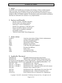
Scope ........................................................................................................................... 4
Features and Benefits .................................................................................................. 4
Abbreviation ............................................................................................................... 4
Applicable Document ................................................................................................. 4
Operations ................................................................................................................... 5
Specification ............................................................................................................... 5
6.1
Supply power ...................................................................................................... 5
6.2
Reliability and Environment ............................................................................... 5
6.3
Size & weight ...................................................................................................... 5
6.4
Mounting method ................................................................................................ 6
6.5
LED Management ............................................................................................... 6
6.6
Beeper Management ........................................................................................... 6
7. Firmware Command ....................................................................................................... 6
7.1
Command Format ............................................................................................... 7
7.2
Get MicrocontrollerFirmware Version ............................................................... 8
7.3
Get MSR Firmware Version ............................................................................... 8
7.4
Review Settings .................................................................................................. 8
7.5
Setting Command................................................................................................ 8
7.6
Review Error Code ............................................................................................. 9
7.7
Review Device Status ......................................................................................... 9
8. Data output format .................................................................................................... 10
8.1
Original Encrypted Data Structure Format ....................................................... 10
8.2
Enhanced Encrypted Data Structure Format..................................................... 14
9. Security feature ......................................................................................................... 19
9.1
Check Card Format ........................................................................................... 19
9.2
MSR Data Masking........................................................................................... 19
10.
Use demo software ................................................................................................ 20
10.1 Send Command ................................................................................................. 20
10.2 Swipe Card ........................................................................................................ 22
APPENDIX A Setting Parameters (Function ID) and Values ........................................ 25
APPENDIX B ERROR CODE LIST TABLE ............................................................... 33
APPENDIX C Key Code Table in USB Keyboard Interface ........................................... 34
Copyright © 2010-2013, International Technologies & Systems Corp. All rights reserved.
Page 2 of 40
SecuRED User Manual
LIMITED WARRANTY
ID TECH warrants to the original purchaser for a period of 12 months from the date of
invoice that this product is in good working order and free from defects in material and
workmanship under normal use and service. ID TECH’s obligation under this warranty
is limited to, at its option, replacing, repairing, or giving credit for any product that
returned to the factory of origin with the warranty period and with transportation charges
and insurance prepaid, and which is, after examination, disclosed to ID TECH’s
satisfaction to be defective. The expense of removal and reinstallation of any item or
items of equipment is not included in this warranty. No person, firm, or corporation is
authorized to assume for ID TECH any other liabilities in connection with the sales of
any product. In no event shall ID TECH be liable for any special, incidental or
consequential damages to purchaser or any third party caused by any defective item of
equipment, whether that defect is warranted against or not. Purchaser’s sole and
exclusive remedy for defective equipment, which does not conform to the requirements
of sales, is to have such equipment replaced or repaired by ID TECH. For limited
warranty service during the warranty period, please contact ID TECH to obtain a Return
Material Authorization (RMA) number & instructions for returning the product.
THIS WARRANTY IS IN LIEU OF ALL OTHER WARRANTIES OF
MERCHANTABILITY OR FITNESS FOR PARTICULAR PURPOSE. THERE ARE
NO OTHER WARRANTIES OR GUARANTEES, EXPRESS OR IMPLIED, OTHER
THAN THOSE HEREIN STATED. THIS PRODUCT IS SOLD AS IS. IN NO EVENT
SHALL ID TECH BE LIABLE FOR CLAIMS BASED UPON BREACH OF EXPRESS
OR IMPLIED WARRANTY OF NEGLIGENCE OF ANY OTHER DAMAGES
WHETHER DIRECT, IMMEDIATE, FORESEEABLE, CONSEQUENTIAL OR
SPECIAL OR FOR ANY EXPENSE INCURRED BY REASON OF THE USE OR
MISUSE, SALE OR FABRICATIONS OF PRODUCTS WHICH DO NOT CONFORM
TO THE TERMS AND CONDITIONS OF THE CONTRACT.
The information contained herein is provided to the user as a convenience. While every
effort has been made to ensure accuracy, ID TECH is not responsible for damages that
might occur because of errors or omissions, including any loss of profit or other
commercial damage, nor for any infringements or patents or other rights of third parties
that may result from its use. The specifications described herein were current at the time
of publication, but are subject to change at any time without prior notice.
ID TECH and Value through Innovation are trademarks of International Technologies &
Systems Corporation. USB (Universal Serial Bus) specification is copyright by Compaq
Computer Corporation, Intel Corporation, Microsoft Corporation, and NEC Corporation.
Windows is registered trademarks of Microsoft Corporation.
ID TECH
10721 Walker Street
Cypress, CA 90630
(714) 761-6368
Copyright © 2010-2013, International Technologies & Systems Corp. All rights reserved.
Page 3 of 40
SecuRED User Manual
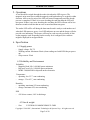
1. Scope
SecuRED is a PCI SRED (Secure Reading and Exchange of Data) certified magnetic
stripe card reader. This intelligent reader, not only encrypts payment card data as it
swiped through the device, but also provides the physical security and tamper resistance
needed to achieve PCI SRED standards. The document outlines the electrical, mechanical
and firmware information for customer’s easy implementation.
2. Features and Benefits
-
Interface includes: USB-KB, USB-HID
Bi-directional card reading capability
Reads up to 3 tracks of information
Reliable for a minimum of 1,000,000 cycles
Beeper and LED to indicate read results
Can be used free standing or mounted
PCI SRED certified
TDES/AES with DUKPT Key Management
3. Abbreviation
AAMVA
AES
DES
DMV
MSR
TDES
PCI
POS
USB
IPEK
American Association of Motor Vehicle Administrators
Advanced Encryption Standard
Data Encryption Standard
Department of Motor Vehicles
Magnetic Swipe Reader
Triple Data Encryption Standard
Payment Card Industry
Point of Sale
Universal Serial Bus
Initial PIN Encryption Key
4. Applicable Document
80096401-001
SecuRED Product Requirement Specification
80128401-001
SRED Secure Card Reader Product Requirement Spec
PCI Point-to-Point Encryption: Solution Requirements – Encryption, Decryption, and
Key Management within Secure Cryptographic Devices (Hardware/Hardware) V1.0
ISO 7810 – 1985
Identification Cards – Physical
ISO 7811 - 1 through 6
Identification Cards - Track 1 through 3
ISO 7816 - 1 through 4
Identification Cards - Integrated circuit cards with contacts
ISO 4909
Magnetic stripe content for track 3
ISO 7812
Identification Cards – Identification for issuers Part 1 & 2
ISO 7813
Identification Cards – Financial Transaction Cards
ANSI X.94
Retail Financial Services Symmetric Key Management
Copyright © 2010-2013, International Technologies & Systems Corp. All rights reserved.
Page 4 of 40
SecuRED User Manual
5. Operations
A card should be swiped through the reader slot when the LED is green. The
magnetic stripe must face toward the magnetic read head and may be swiped in either
direction. After a card is swiped, the LED will turn off temporarily until the decode
process is completed. If there is no error decoding the card data then the LED will
turn green. If there is any error decoding the card data, the LED will turn red for less
than one second to indicate that an error occurred and then turn green.
The reader LED will be off during the data transfer and is ready to read another card
when the LED returns to green. A red LED indicates an error and the beeper will also
provide error indications. The beeper will beep for each correctly read track of data
on the magstripe card. Depending on the security level configured, the card data
might be displayed in encrypted mode.
6. Specification
6.1 Supply power
-
Supply voltage: DC 5V
Working current: Maximum 50mA (when reading card with LEDs/beeper power
on)
Sleep current: 25mA
6.2 Reliability and Environment
Reliability
- Magnetic Head Life: 1,000,000 passes minimum
- Rail and Cover Life: 1,000,000 passes minimum
- MTBF: 300,000 POH or depends on the electronics
Temperature
- operating: 0 to 55 ℃ non-condensing
- storage: -35 to 65 ℃ non-condensing
Humidity
- operating: maximum 95% non-condensing
- storage: maximum 95% non-condensing
ESD
- 4 kV direct contact, 8 kV air discharge
6.3 Size & weight
-
Size:
L*W*H:MAX 100MM*30MM*31.5MM
Copyright © 2010-2013, International Technologies & Systems Corp. All rights reserved.
Page 5 of 40
SecuRED User Manual
-
Weight:
127g
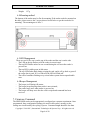
6.4 Mounting method
The bottom of the reader must be flat for mounting. If the reader needs be mounted on
the table, please unscrew the 2 screws showed in red below to get the two holes for
mounting . The mounting nut is M3x 3.
6.5 LED Management
There are two LEDs, one is on the top of the reader and the one is on the side.
- The LED on the top flashes red if the reader is not activated.
- The top LED flashes amber for one second during the self-test after reader is
powered on.
- The top LED is stable green in idle status.
- The top LED flashes dark during swiping the card, and it will go back to green if
the swipe data is good. If it’s a bad read, the LED will flash red.
- The red led continues flashing every second when system detects unpredictable
error.
6.6 Beeper Management
-
The beeper is off during idle status;
The beeper keeps beeping when reader is not activated;
The reader beeps once when reader is powered on
The beeper will beep once after the card is swiped and command has been
received.
7. Firmware Command
The SRED MSR reader can be appropriately configured per customer requirement. Once
programmed, these configuration settings are stored in the reader’s memory so the
settings are not affected by the cycling of power. Command length should be less than
Copyright © 2010-2013, International Technologies & Systems Corp. All rights reserved.
Page 6 of 40
SecuRED User Manual
254 bytes. The command/response time between the reader and host is from 50ms to
6000ms.
7.1 Command Format
a. Setting Command:
<STX><S>[<FuncID><Len><FuncData>…]<ETX>< CheckLrc >
Response from SecuRED
<ACK> if setting succeeds
or
<NAK> if setting fails
b. Read Status Command:
<STX><R>[<FuncID><Len><FuncData>…]<ETX>< CheckLrc >
Response from SecuRED
<ACK>< STX ><Response><ETX>< CheckLrc > if command succeeds
Or
<NAK> if commands fail
c. Function Command:
<STX><F>[<FuncID><Data>…]<ETX>< CheckLrc >
Response from SecuRED
<ACK>< STX >[<Response>]<ETX>< CheckLrc > if command succeeds
Or
<NAK> if commands fails
Where
Characters
<STX>
<ETX>
<ACK>
<NAK>
<UnknownID>
Hex Value
02
03
06
15 for RS232
and USB HID
interface;
FD for USB KB
interface
16
<AlreadyInPOS>
17
<R>
<S>
<LRC>
52
53
-
Description
Start of Text
End of Text
Acknowledge
Negative Acknowledge
Warning: Unsupported ID in
setting
Warning: Reader already in
OPOS mode
Review Setting
Send Setting
Xor’d all the data before LRC.
Copyright © 2010-2013, International Technologies & Systems Corp. All rights reserved.
Page 7 of 40
SecuRED User Manual
7.2 Get Microcontroller Firmware Version
This command is used to get firmware version from SecuRED.
Command: <STX><R><A2h><EXT><LRC1>
Response: <ACK> <STX><A2h><Len of Version
String><VersionString><ETX><LRC2>
7.3 Get MSR Firmware Version
This command is used to get MSR firmware version
Command: <STX><R><52h><ETX><LRC 1>
Response: <ACK> <STX><Version String><ETX><LRC 2>
Version String will be in format of “ID TECH FirmOpt IntOpt Reader Vxx.yy. xx.yy is
the major and minor version number.
7.4 Review Settings
Command: <STX> <R> <1Fh> <ETX> <LRC1>
<Response> format:
The current setting data block is a collection of many function-setting blocks
<FuncSETBLOCK> as follows:
<STX><FuncSETBLOCK1>…<FuncSETBLOCKn><ETX><CheckSum>
Each function-setting block <FuncSETBLOCK> has the following format:
<FuncID><Len><FuncData>
Where:
<FuncID> is one byte identifying the setting(s) for the function.
<Len> is a one byte length count for the following function-setting block <FuncData>
<FuncData> is the current setting for this function. It has the same format as in the
sending command for this function.
<FuncSETBLOCK> are in the order of their Function ID<FuncID>
7.5 Setting Command
The setting command is a collection of many function setting blocks and its format is as
follows.
Command: <STX><S><FuncSETBLOCK1>…<FuncBLOCKn><ETX><LRC>
Response: <ACK> or <NAK> for wrong command (invalid funcID, length and value)
Each function-setting block <FuncSETBLOCK> has following format:
<FuncID><Len><FuncData>
Where:
<FuncID> is one byte identifying the setting(s) for the function.
Copyright © 2010-2013, International Technologies & Systems Corp. All rights reserved.
Page 8 of 40
SecuRED User Manual
<Len> is a one byte length count for the following function-setting block <FuncData>.
<FuncData> is the current setting for this function. It has the same format as in the
sending command for this function.
7.6 Review Error Code
This command is used to review code data to look for root cause if pre-command fails.
Command: <STX><R><E0h><ETX><LRC1>
Respond :< ACK><STX><E0h><0x02><Error Code (2 bytes)> <ETX><LRC2>
For more error codes, please refer to Appendix B.
7.7 Review Device Status
This command is used to review status of Device.
Command: <STX><R><A6h><ETX><LRC1>
Respond:
<ACK><STX><A6h><0x01>< Status> <ETX><LRC2>
Where:
<Status>: is defined
0
Device had been attacked.
1
Device hasn’t been activated.
2
Admin Key doesn’t load.
3
Device works in idle status.
8
Check Value doesn’t load.
9
MSR key doesn’t load
For more command function ID, please refer to Appendix A.
Copyright © 2010-2013, International Technologies & Systems Corp. All rights reserved.
Page 9 of 40
SecuRED User Manual
8. Data output format
SecuRED encrypts both financial card and non-financial card. Both clear/masked data
and encrypted data are sent out.
8.1 Original Encrypted Data Structure Format
This original format is maintained for customers who deployed readers before the
enhanced structure was developed.
A card swipe returns the following data:
Card data is sent out in this format
<STX><LenL><LenH><Card Data><CheckLRC>< CheckSum ><ETX>
<STX> = 02h, <ETX> = 03h
<LenL><LenH> is a two byte length of <Card Data>.
<CheckLRC> is a one byte Exclusive-OR sum calculated for all <Card Data>.
< CheckSum > is a one byte Sum value calculated for all <Card data>.
<Card Data> format is
ISO/ABA Data Output Format:
card encoding type
Raw Mode)
track status
3,4,5:T1,2,3 sampling)
track 1 unencrypted length
data)
track 2 unencrypted length
data)
track 3 unencrypted length
data)
track 1 masked data
track 2 masked data
track 3 data
track 1, 2, 3 encrypted data
track 1 dummy hash data*
track 2 dummy hash data*
track3 dummy hash data*
KSN(key serial number)
(0: ISO/ABA; 3 For others 4: For
(bit 0,1,2:T1,2,3 decode*, bit
(1 byte in binary, 0 for no track1
(1 byte in binary, 0 for no track2
(1 byte in binary, 0 for no track3
(omitted if raw or force encrypted)
(omitted if raw or force encrypted)
(omitted if raw or force encrypted)
(AES/TDES encrypted data, bytes)
20 bytes 0x00 reserved for future use
20 bytes 0x00 reserved for future use
20 bytes 0x00 reserved for future use
10 bytes
Note: the track 1, 2, 3 hash data can be disabled by command 53 5c 01 30. Please refer to
Appendix A for details.
Except for USBKB interfaces, track formatting (preamble, prefix, separator, etc.) is not
supported in a reader set to send encrypted track data. The track data is always sent in the
Copyright © 2010-2013, International Technologies & Systems Corp. All rights reserved.
Page 10 of 40
SecuRED User Manual
same format that is with no special formatting so that the program doing the decoding can
know where each data field is located.
Note: For USBKB interface, preamble and postamble can be available in encrypted track
data.
Offset to the fields can be determined by adding the field lengths using the track data for
the track field lengths. Fields are packed in the next available location.
T1, T2 or T3 Data Length: Each byte value indicates how many bytes of decoded card
data are in the track data field. This value will be zero if there is no data on the track or if
there is an error decoding the track.
The encrypted section is padded with zeros to the block size of the encryption type, 8
bytes for TDES and 16 bytes for AES.
How to get Encrypted Data Length
If card encoding type high bit is not set:
The encrypted data is packed into one continuous block and then padded with zeros until
the encryption block size is reached, 8 bytes for triple DES and 16 bytes for AES. The
length of the encrypted data is the length of Track 1 + length of track 2 + length of track
3. This total is padded to the block length then encrypted. The field is always a multiple
of 8 bytes in length if triple DES or 16 bytes if AES encryption is used. This value will be
zero if there was no data on the track or if there was an error decoding the track.
The length of track 1 encrypted data is equal to track 1 encrypted data length. The length
of track 2 is equal to track 2 data length. If present the length of track 3 encrypted length
is equal to the length of the track 3 data length.
Once the encrypted data is decrypted, there may be fewer bytes of decoded track data
than indicated by this field. The number of bytes of decoded track data is indicated by the
track 1 unencrypted length.
If card encoding type high bit is set:
In this mode tracks are encrypted separately rather than as a group. The length of
encrypted track 1 is the length of the track rounded up to the nearest multiple of 8 bytes if
TDES encryption is used or 16 bytes if AES encryption is used. Track 2 follows the end
track 1 as rounded up and follows the same rule as track 1. Track 3 follows track 2 as
rounded up and again follows the same rule. If the encryption is security level 4, then the
session ID follows track 3 and is eight bytes long.
Track 1 unencrypted Length
This one-byte value indicates the number of useable bytes in the track 1 encrypted data
field and track 1 masked data field after decryption.
Track 2 unencrypted Length
Copyright © 2010-2013, International Technologies & Systems Corp. All rights reserved.
Page 11 of 40
SecuRED User Manual
This one-byte value indicates the number of useable bytes in the track 2 encrypted data
field and track 2 masked data field after decryption.
Track 3 unencrypted Length
This one-byte value indicates the number of useable bytes in the Track 3 masked Data
field.
Original Format Data Example
The example below is the decryption of a three track ABA card with the original
encryption format and SecuRED Reader with default settings.
Original encryption format can be recognized because the high bit of the fourth byte
underlined (00) is 0.
02F100001F372300252A353135302A2A2A2A2A2A2A2A373930335E5041595041535
32F4D4153544552434152445E2A2A2A2A2A2A2A2A2A2A2A2A2A2A2A3F2A3B35
3135302A2A2A2A2A2A2A2A373930333D2A2A2A2A2A2A2A2A2A2A2A2A2A2A2
A3F2AEB2C43BD28846F6ADDCDB806DEBC3500328E4589AF72C7AAE09C4F714
89D6D7EDE9C3C6DA94F31288463262429D072BAA1017CB8B93DF3F7F43A8DC4
D64FF8DA7C30310A5456CC37DD6410D0463B61CE95EDC4671035D1E63C1E1C74
43FC8015000000000000000000000000000000000000000000000000000000000000000
00000000000000000629949012C0004600004C26603
STX, Length (LSB, MSB), card type, track status, length track 1, length track 2, length
track 3
02 F100 00 1F 37 23 00
The above broken down and interpreted
02—STX character
F1—low byte of total length
00—high byte of total length
00—card type byte (interpretation old format ABA card)
1F—Track 1&2 data good
37—length of track 1
23—length of track 2
00—length of track 3
Track 1 data masked (length 0x37)
252A353135302A2A2A2A2A2A2A2A373930335E504159504153532F4D41535445524
34152445E2A2A2A2A2A2A2A2A2A2A2A2A2A2A2A3F2A
In Ascii:
%*5150********7903^PAYPASS/MASTERCARD^***************?*
Track 2 data in hex masked (length 0x23)
Copyright © 2010-2013, International Technologies & Systems Corp. All rights reserved.
Page 12 of 40
SecuRED User Manual
3B353135302A2A2A2A2A2A2A2A373930333D2A2A2A2A2A2A2A2A2A2A2A2A2
A2A2A3F2A
In Ascii:
;5150********7903=***************?*
Track 1 & 2 encrypted length 0x37+0x23=90 in decimal -> rounded up by 8 bytes=96
bytes
EB2C43BD28846F6ADDCDB806DEBC3500328E4589AF72C7AAE09C4F71489D6D
7EDE9C3C6DA94F31288463262429D072BAA1017CB8B93DF3F7F43A8DC4D64FF8
DA7C30310A5456CC37DD6410D0463B61CE95EDC4671035D1E63C1E1C7443FC80
15
Track1 dummy hash data
0000000000000000000000000000000000000000
Track2 dummy hash data
0000000000000000000000000000000000000000
KSN
629949012C0004600004
LRC, checksum and ETX
C2 66 03
Decrypted Data:
Data in ASCII Format
%B5150710200107903^PAYPASS/MASTERCARD^090910140000631??;5150710200
107903=090910140000631?0
Data in HEX Format
2542353135303731303230303130373930335E504159504153532F4D415354455243415
2445E3039303931303134303030303633313F3F3B353135303731303230303130373930
333D3039303931303134303030303633313F30
Copyright © 2010-2013, International Technologies & Systems Corp. All rights reserved.
Page 13 of 40
SecuRED User Manual
8.2 Enhanced Encrypted Data Structure Format
SecuRED output structure setting:
53 85 01 encryptStructure
encryptStructure = ‘0’
encryptStructure = ‘1’
Original Encryption Format
Enhanced Encryption Format
Enhanced encrypt output structure will send bytes 8 and 9 and CardType will be
1xxxxxxx (high bit =1). Also the T1, T2 data are encrypted in separate data block.
Encrypt Option Setting:
// only effect in new structure
53 84 01 encrypOpt
// default 0x08
encryptOpt:
bit0: 1 – tk1 force encrypt *
bit1: 1 – tk2 force encrypt *
bit2: 1 – tk3 force encrypt *
bit3: 1 – tk3 force encrypt when card type is 0
bit4: 1 – new mask feature: see notes 4
Note:
1) When force encryption is set, all tracks will always be encrypted, regardless of
card type. No clear/mask text will be sent, except bit4 “new mask feature is set (see
notes).
2) If and only if in new encrypt structure, each track encryption is separated, encrypted
data length will round up to 8 or 16 bytes.
3) When force encrypt and new mask feature is not set, it encrypts data just like old
structure, that is, only T1 and T2 in type zero will be encrypted.
4) When new mask feature (bit4) is set,
a) Mask data can be sent even if set to “force encrypt” (bit0-3 is set);
b) If bank card and track 3 is iso-4909 with PAN format, T3 will be encrypted and
has mask data.
Typical setting:
1) 08 (default):
All tracks will be encrypted. Only T1 and T2 will sent out clear/mask data.
2) 07
Force encryption. All three tracks will be encrypted without mask, regardless
of card type.
3) 10
T1 and T2 will be encrypted. If the T3 is with ISO-4909 format, it’ll be
encrypted and its mask data will be sent out. Otherwise, T3 will be sent in
clear text.
4) 17
All tracks will be encrypted. T1 and T2 will send out clear/mask data. T3 will
send out clear/mask data if it’s ISO 4909 format.
Copyright © 2010-2013, International Technologies & Systems Corp. All rights reserved.
Page 14 of 40
SecuRED User Manual
Dummy Hash Option Setting:
Command: 53 5C 01 <Dummy Hash Option>
// default 0x37
Dummy Hash Option: (‘0’ – ‘7’)
bit0: 1 – tk1 dummy hash will be sent if data is encrypted
bit1: 1 – tk2 dummy hash will be sent if data is encrypted
bit2: 1 – tk3 dummy hash will be sent if data is encrypted
Mask Option Setting: // only effected in new structure
Command: 53 86 01 <Mask Option>
// Default: 0x07
Mask Option:
bit0: 1 – tk1 mask data allow to send when encrypted
bit1: 1 – tk2 mask data allow to send when encrypted
bit2: 1 – tk3 mask data allow to send when encrypted
Note:
1) When mask option bit is set – if data is encrypted (but not forced encrypted),
the mask data will be sent; If mask option is not set, the mask data will not be sent
under the same condition.
Following is the output structure:
0
STX
1
Data Length low byte
2
Data Length high byte
3
Card Encode Type*
4
Track 1-3 Status
5
T1 data length
6
T2 data length
7
T3 data length
8
Clear/mask data sent status *
9
Encrypted/Hash data sent status *
10
T1 clear/mask data
T2 clear/mask data
T3 clear/mask data
T1 encrypted data
T2 encrypted data
T3 encrypted data
Track 1 dummy hash data* (20 bytes 0x00 reserved for future use)
Track 2 dummy hash data* (20 bytes 0x00 reserved for future use)
Track 3 dummy hash data* (20 bytes 0x00 reserved for future use)
KSN (10 bytes) (DUKPT only)
CheckLrc
CheckSum
ETX
Copyright © 2010-2013, International Technologies & Systems Corp. All rights reserved.
Page 15 of 40
SecuRED User Manual
Note:
1) Field 8 (Clear/mask data sent status) and field 9 (Encrypted/Hash data sent
status) will only be sent in new encrypt structure.
2) Field 8: Clear/mask data sent status byte:
bit 0: 1--- if TK1 clear/mask data present
bit 1: 1--- if TK2 clear/mask data present
bit 2: 1--- if TK3 clear/mask data present
Bit 3:1— if fixed key; 0 DUKPT
Bit 4-5: 00- TDES; 01 - AES
Bit 6: 1-- PinKey; 0 – Data key
Bit7: 1 – Serial # present; 0- not present
3) Field 9: Encrypted data sent status
bit 0: if 1—tk1 encrypted data present
bit 1: if 1—tk2 encrypted data present
bit 2: if 1—tk3 encrypted data present
bit 3: if 1—tk1 dummy hash data present
bit 4: if 1—tk2 dummy hash data present
bit 5: if 1—tk3 dummy hash data present
Bit 6: if 1—session ID present
Bit 7: if 1—KSN present
Card Type:
Value Encode Type Description
0 / 80 ISO/ABA format
1 / 81 AAMVA format
3 / 83 Other
4/ 84 Raw Data format
* / 85 JIS II
Note:
1) Card Type will be 8x in new structure and 0x for old structure
2) Type 4 or 84: Raw data format; all tracks are encrypted and no mask data is
sent. No track indicator ‘01’, ‘02’ or ‘03’ in front of each track. (‘01’,’02’
and ‘03’ will still exist for none secured mode raw output when security
level < 3)
3) Type 85: JIS II, needs to set to Enhanced mode. Only T2 will be sent; Force
encrypted, no clear text.
4) Note: the track 1, 2, 3 dummy hash data can be disabled by command 53 5c
01 30. Please refer to Appendix A for details.
Copyright © 2010-2013, International Technologies & Systems Corp. All rights reserved.
Page 16 of 40
SecuRED User Manual
Enhance Format Data Example:
Example below is the decryption of a three track ABA card with the enhanced encryption
format and SecuRED is with default settings except enhanced encryption structure
format.
Enhanced encryption Format (this can be recognized because the high bit of the fourth
byte underlined (80) is 1.
02F300801F372300039B252A353135302A2A2A2A2A2A2A2A373930335E504159504
153532F4D4153544552434152445E2A2A2A2A2A2A2A2A2A2A2A2A2A2A2A3F2A3
B353135302A2A2A2A2A2A2A2A373930333D2A2A2A2A2A2A2A2A2A2A2A2A2A
2A2A3F2A277034D65F3BE450F2210B20A347DA4E307EEE546DE3677F9A584CA3
40164A82A85627E51FBD1EE81EA7F69D5560305BF0C2CBE0C77166876C3F4B21E
6C229808A9063442AC8A79FAC6B857D6B6BED94C0D664BFC97E931626F338CA
CD16F990000000000000000000000000000000000000000000000000000000000000000
00000000000000000629949012C000460000670B403
STX, Length(LSB, MSB), card type, track status, length track 1, length track 2, length
track 3
02 F300 80 1F 372300
The above broken down and interpreted
02—STX character
F3—low byte of total length
00—high byte of total length
80—card type byte (interpretation new format ABA card)
1F—Track 1&2 good
37—length of track 1
23—length of track 2
00—length of track 3
03—tracks 1 and 2 have masked/clear data
9B Encrypted/Hash data status
bit 7=1—KSN included
Bit 6=0—no Session ID included so not level 4 encryption
Bit 5=0—no track 3 dummy hash data present
Bit 4=1—track 2 dummy hash data present
Bit 3=1—track 1 dummy hash data present
Bit 2=0—no track 3 encrypted data present
Bit 1=1—track 2 encrypted data present
Bit 0=1—track 1 encrypted data present
Track 1 data masked (length 0x37)
252A353135302A2A2A2A2A2A2A2A373930335E504159504153532F4D41535445524
34152445E2A2A2A2A2A2A2A2A2A2A2A2A2A2A2A3F2A
Copyright © 2010-2013, International Technologies & Systems Corp. All rights reserved.
Page 17 of 40
SecuRED User Manual
Track 1 masked data in ASCII
%*5150********7903^PAYPASS/MASTERCARD^***************?*
Track 2 data in hex masked (length 0x23)
3B353135302A2A2A2A2A2A2A2A373930333D2A2A2A2A2A2A2A2A2A2A2A2A2
A2A2A3F2A
Track2 masked data in ASCII
;5150********7903=***************?*
In this example there is no Track 3 data either clear or masked (encrypted and hashed
data is below)
Track 1 encrypted length 0x37=55 (decimal) bytes rounded up to 8 bytes = 56(decimal)
bytes277034D65F3BE450F2210B20A347DA4E307EEE546DE3677F9A584CA340164
A82A85627E51FBD1EE81EA7F69D5560305BF0C2CBE0C7716687
Track 2 encrypted length 0x23= 35(decimal) bytes rounded up to 8 bytes= 40 (decimal
bytes)
6C3F4B21E6C229808A9063442AC8A79FAC6B857D6B6BED94C0D664BFC97E9316
26F338CACD16F990
Track 1 dummy Hash Data:
0000000000000000000000000000000000000000
Track 2 dummy Hash Data:
0000000000000000000000000000000000000000
Key Serial Number:
629949012C0004600006
LCR, check sum and ETX
70 B4 03
Decrypted Data:
Data in ASCII Format
%B5150710200107903^PAYPASS/MASTERCARD^090910140000631??
;5150710200107903=090910140000631?0
Data in HEX Format
2542353135303731303230303130373930335E504159504153532F4D415354455243415
2445E3039303931303134303030303633313F3F
3B353135303731303230303130373930333D3039303931303134303030303633313F30
Copyright © 2010-2013, International Technologies & Systems Corp. All rights reserved.
Page 18 of 40
SecuRED User Manual
9. Security feature
The SecuRED is only working with the key injected and encryption is enabled.
9.1 Check Card Format
ISO/ABA (American Banking Association) Card (card type 0)
Encoding method
Track1 is 7 bits encoding.
Track1 is 7 bits encoding. Track2 is 5 bits encoding. Track3 is 5 bits
encoding.
Track1 is 7 bits encoding. Track2 is 5 bits encoding.
Track2 is 5 bits encoding.
Additional check
Track1 2nd byte is ‘B’.
There is only one ‘=’ in track 2 and the position of ‘=’ is between 13th
~ 20th character so account number length is 12-19 digits.
Total length of track 2 is above 19 characters.
AAMVA (American Association of Motor Vehicle Administration) Card
Encoding method
Track1 is 7 bits encoding. Track2 is 5 bits encoding. Track3 is 7 bits
encoding.
Others (Customer card)
9.2 MSR Data Masking
For financial card, the clear data includes start and end sentinels, separators, first N, last
M digits of the PAN, card holder name (for Track1). The rest of the characters should be
masked using mask character.
Set PrePANClrData (N), PostPANClrData (M), MaskChar (Mask Character)
N and M are configurable and default to 4 first and 4 last digits. They follow the current
PCI constraints requirements (N 6, M 4 maximum).
Mask character default value is ‘*’.
Set PrePANClrDataID (N), parameter range 00h ~ 06h, default value 04h
Set PostPANClrDataID (M), parameter range 00h ~ 04h, default value 04h
MaskCharID (Mask Character), parameter range 20h ~ 7Eh, default value 2Ah
DisplayExpirationDataID, parameter range ‘0’~’1’, default value ‘0’
Copyright © 2010-2013, International Technologies & Systems Corp. All rights reserved.
Page 19 of 40
SecuRED User Manual
For non-financial card, the first 4 digits/characters of track data, start sentinel and end
sentinel is in clear. The other data are masked with “*”.
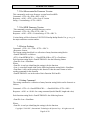
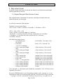
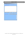
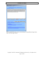
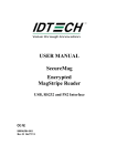
10.Use demo software
Double click executable file “SecuRED_USB_Demo.exe” after connecting the SecuRED
with PC.
10.1
Send Command
Command can be sent to SecuRED via the demo software. The command can be typed in
the upper window, such as get firmware version command below. Then click [send
command] button, then the response from reader will be showed in the second window
below.
Copyright © 2010-2013, International Technologies & Systems Corp. All rights reserved.
Page 20 of 40
SecuRED User Manual
Copyright © 2010-2013, International Technologies & Systems Corp. All rights reserved.
Page 21 of 40
SecuRED User Manual
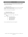
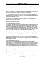
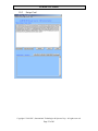
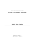
10.2
Swipe Card
Copyright © 2010-2013, International Technologies & Systems Corp. All rights reserved.
Page 22 of 40
SecuRED User Manual
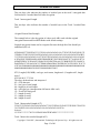
Decrypt data
Before decrypt data, please input the Base Derivation Key to decrypt data if the key
injected is not ID Tech demo key “0123456789abcdeffedcba9876543210”.
Then click the [Decrypt] button to decrypt data, and the decrypted card data will be
showed in the lower window.
Copyright © 2010-2013, International Technologies & Systems Corp. All rights reserved.
Page 23 of 40
SecuRED User Manual
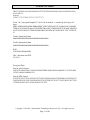
Note:
About SecuRED KB interface, please clear the Manual Command/Reader Output before
swipe card in the upper window.
Copyright © 2010-2013, International Technologies & Systems Corp. All rights reserved.
Page 24 of 40
SecuRED User Manual
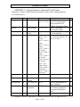
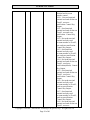
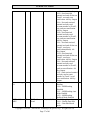
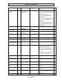
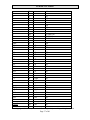
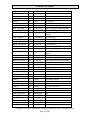
APPENDIX A Setting Parameters (Function ID) and Values
Following is a table of default setting and available settings (value within parentheses)
for each function ID.
Function ID
HTypeID*
Hex
10
Description
Terminal Type
Default Setting
'0'
(‘0’~’2’,'4'~'6')
BeepID
11
Beep Setting
‘2’ (‘0’~’4’)
ChaDelayID
12
TrackSelectID
13
Character
‘0’ (‘0’~’5’)
Delay
‘6’
Track Selection ‘0’ (‘0’~’9’)
0x30 – Any
Track
0x31 – Track 1
Only
0x32 – Track 2
Only
0x33 – Track 1
& Track 2
0x34 – Track 3
Only
0x35 – Track 1
& Track 3
0x36 – Track 2
& Track 3
0x37 – All
Three Tracks
0x38 – Track 1
Or Track 2
0x39 – Track 2
Or Track 3
Polling Interval 1 (1 ~ 255)
PollingInterval 14
ID
DataFmtID
15
Description
PC/AT, Scan Code Set 2, 1, k
3, PC/AT with external
Keyboard and PC/AT
without External Keyboard
Beep volume high
and frequency high
2 ms inter-character delay
k
‘6 for 0 mS delay
Any Track 0-any; 1-7—bit 1
tk1, bit 2 tk2; bit 3 tk3. ‘8’—
tk1-2; ‘9’ tk2-3
USB HID Polling Interval
u
Data Output
Format
UIC, Mag-Tek
‘0’ (‘0’~’2’)
ID TECH Format;
-
H’59’
Refer to MiniMag RS232
User’s Manual
CR for RS232, Enter for KB
any character supported
except 00 which means
none.
Sentinel and Account
-
FmtOptionID
16
TrackSepID
17
Track
Separator
CR/Enter
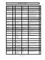
SendOptionID
19
Send Option
‘1’ (‘0’~0x3f)
Copyright © 2010-2013, International Technologies & Systems Corp. All rights reserved.
Page 25 of 40
SecuRED User Manual
number control
Sentinel and Account
number control
0x30 - Not send start/end
sentinel and send all data on
Track 2, not error
notification. Control Key
Output.
0x31 - Send start/end
sentinel and send all data on
Track 2, not send error
notification. Control Key
Output.
0x32 - Not send start/end
sentinel and only send
account number on Track 2,
not send error notification.
Control Key Output.
0x33 - Send start/end
sentinel and only send
account number on Track 2,
not send error notification.
Control Key Output.
0x34 - Not send start/end
sentinel and send all data on
Track 2, send error
notification(default). Control
Key Output.
0x35 - Send start/end
sentinel and send all data on
Track 2, send error
notification. Control Key
Output.
0x36 - Not send start/end
sentinel and only send
account number on Track 2,
send error notification.
Control Key Output.
0x37 - Send start/end
sentinel and only send
account number on Track 2,
send error notification.
Control Key Output.
0x38 - Not send start/end
sentinel and send all data on
Track 2, not error
Copyright © 2010-2013, International Technologies & Systems Corp. All rights reserved.
Page 26 of 40
SecuRED User Manual
MSRReadingI
D
1A
MSR Reading
‘1’ (‘0’~’2’)
DTEnableSen
dID*
1B
DT Enable
Send
‘0’(‘0’,’1’,’3’)
notification. Alt Key Output.
0x39 - Send start/end
sentinel and send all data on
Track 2, not send error
notification. Alt Key Output.
0x3a - Not send start/end
sentinel and only send
account number on Track 2,
not send error notification.
Alt Key Output.
0x3b - Send start/end
sentinel and only send
account number on Track 2,
not send error notification.
Alt Key Output.
0x3c - Not send start/end
sentinel and send all data on
Track 2, send error
notification(default). Alt
Key Output.
0x3d - Send start/end
sentinel and send all data on
Track 2, send error
notification. Alt Key Output.
0x3e - Not send start/end
sentinel and only send
account number on Track 2,
send error notification. Alt
Key Output.
0x3f - Send start/end sentinel
and only send account
number on Track 2, send
error notification. Alt Key
Output.
Enable/Disable MSR
Reading
0x30 – MSR Reading
Disabled
0x31 – MSR Reading Auto
Mode Enabled
0x32 – MSR Reading
Buffered Mode Enabled
Data Editing Control
d
0x30 – Disable Data Edit.
0x31 – Data Edit Match
mode.
Copyright © 2010-2013, International Technologies & Systems Corp. All rights reserved.
Page 27 of 40
SecuRED User Manual
DecodingMeth 1D
odID
Decoding
Direction
‘1’ (‘0’~’3’)
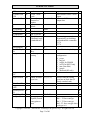
ReviewID
1F
None
TerminatorID
FmVerID
21
22
USBHIDFmtI
D
ForeignKBID
SecureKeyID*
23
Review All
Settings
Terminator
Firmware
Version
USB HID Fmt
Foreign KB
Obsolescent
encryption
ArmtoReadID
*
CustSetID
30
ReaderResetI
D*
Track1PrefixI
D
Track2PrefixI
D
Track3PrefixI
D
Track1SuffixI
D
Track2SuffixI
D
Track3SuffixI
0x33 – Data Edit Unmatch
mode
Reading Direction
0x30 – Raw Data Decoding
in Both Directions.
0x31 – Decoding in Both
directions.
0x32 – Moving Stripe Along
Head in Direction of
Encoding.
0x33 – Moving Stripe Along
Head Against Direction of
Encoding.
CR/Enter
CR for RS232, Enter for KB
‘0’ (‘0’~’1’)
ID TECH Format
'0' ('0' ~ '9')
‘@’ (0x200x7F)
Foreign Keyboard
No simple encryption
30
00-07
.0 POS-X: Level 3 Non-CC
send same as Level1
.1 Level3: No empty pkt
when not enough sampling
bits
.2 Enhanced Secured Output
will have SN after hash
32
None
24
25
34
Track 1 Prefix
0
35
Track 2 Prefix
0
36
Track 3 Prefix
0
37
Track 1 Suffix
0
38
Track 2 Suffix
0
39
Track 3 Suffix
0
No prefix for track 1, 6 char
max
No prefix for track 2, 6 char
max
No prefix for track 3, 6 char
max
No suffix for track 1, 6 char
max
No suffix for track 2, 6 char
max
No suffix for track 3, 6 char
Copyright © 2010-2013, International Technologies & Systems Corp. All rights reserved.
Page 28 of 40
u
r
k
SecuRED User Manual
D
LZ1ID*
Set50
LZ2ID*
SwapT1T3ID
max
3C
3C
3D
3D
LZ3ID*
PinKeyID
3E
3E
0xD
0x00,0x5A
LZ4ID*
EpVerID*
BaudID
3F
40
41
Baud Rate
0xD
None
‘5’ (‘2’~’9’)
DataID
42
Data Bit
‘0’ (‘0’~’1’)
ParityID
HandID
43
44
Data Parity
Hand Shake
‘0’ (‘0’~’4’)
‘0’ (‘0’~’1’)
StopID
XOnID
XOffID
PrePANID
45
47
48
49
‘0’ (‘0’~’1’)
DC1
DC3
4 (0-6)
PostPANID
4A
MaskCharID
4B
CrypTypeID
4C
Stop Bit
XOn Character
XOff Character
PAN to not
mask
PAN to not
mask
mask the PAN
with this
character
encryption type
OutputModeI
D
SerialNumberI
D
DispExpDateI
D,
CapsCaseID*
DataSeqID*
StartCharID*
SessionID
4D
Std, OPOS or
JPOS
device serial #
4E
50
51
52
53
54
0xD
Set50
set MSR reg eeprom map
0xD
0x00,0x5A
Swap T1,T3
0x5A:Swap T1 and T3. Will
not be reset by 53 18
0x5A– PinKey
Can only set at level 1;
Won’t reset by 53 18;
s
‘*’ 20-7E
9600 bps, ‘2’ is 1200, ‘7’ is
38,400 bps; ‘9’ is 115.2 kbps
8 Bits required in secure
mode
None
Software (Xon/Xoff) hand
shake
1 Bit
0x11 as XOn
0x13 as XOff
# leading PAN digits to
display
# of trailing PAN digits to
display
any printable character
‘1’ (‘1’-‘2’)
‘1’ 3DES ‘2’ AES
r
e
'0' ('0' ~ '1')
Standard mode
any 8-10 bytes
8-10 hex serial number
r
‘1’ don’t mask expiration
date
e
always init to all ‘FF’
e
4 (0-4)
mask or display '0''0'-'1'
expiration date
None
None
None
8 byte hex not
None
stored in
EEPROM
Copyright © 2010-2013, International Technologies & Systems Corp. All rights reserved.
Page 29 of 40
s
s
s
s
s
s
e
e
e
SecuRED User Manual
Mod10ID
55
include mod10
check digit
'0' '0'-'2'
DesKeyID
56
0
AesKeyID
57
0
internal use only
KeyManageTy
peID
T1GENERICF
MTID*
T2GENERICF
MTID*
T3GENERICF
MTID*
HashOptID,
58
DES Key
Value
AES Key
Value
DUKPT or
Fixed key
don’t include mod10, ‘1’
display mod10, ‘2’ display
wrong mod10
internal use only
‘1’(‘0’-‘1’)
‘0’ fixed key
‘1’ DUKPT key
59
None
5A
None
5B
None
5C
'3' (‘0’-‘7’)
HexCaseID,
LRCID
T17BStartID
5D
60
61
T16BStartID
62
LRC character
Track 1 7 Bit
Start Char
T16B Start
'0' (‘0’-‘1’)
‘0’ (‘0’~’1’)
‘%’
T15BStartID
63
T15B Start
‘;’
T27BStartID
64
‘%’
T25BStartID
65
Track 2 7 Bit
Start Char
T25BStart
T37BStartID
66
‘%’
T36BStartID
67
Track 3 7 Bit
Start Char
T36BStart
T35BStartID
68
T35BStart
‘;’
T1EndID
69
‘?’
T2EndID
6A
'?'
‘?’ as End Sentinel
T3EndID
6B
'?'
‘?’ as End Sentinel
T1ERRSTAR
TID
T2ERRSTAR
6C
Track 1 End
Sentinel
Track 2 End
Sentinel
Track 3 End
Sentinel
Track 1 error
code
Track 2 error
Without LRC in output
‘%’ as Track 1 7 Bit Start
Sentinel
‘%’ as Track 1 6 Bit Start
Sentinel
‘;’ as Track 1 5 Bit Start
Sentinel
‘%’ as Track 2 7 Bit Start
Sentinel
‘;’ as Track 2 5 Bit Start
Sentinel
‘%’ as Track 3 7 Bit Start
Sentinel
‘!’ as Track 3 6 Bit Start
Sentinel
‘;’ as Track 3 5 Bit Start
Sentinel
‘?’ as End Sentinel
‘%’
start sentinel if track 1 error
report
start sentinel if track 2 error
6D
‘%’
‘;’
‘!’
‘;’
Send tk1-2 hash bit 0:1 send
tk1 hash; bit 1:1 send tk2
hash; bit2:1 send tk3 hash.
r
e
r
e
-
e
k
Copyright © 2010-2013, International Technologies & Systems Corp. All rights reserved.
Page 30 of 40
e
SecuRED User Manual
TID
T3ERRSTAR
TID
SecureLrcID
6E
6F
code
Track 3 error
code
Secured output
format Lrc
option
Boot Loader
Mode
‘+’
‘1’ (‘0’-‘1’)
BootloaderID
*
T344EndID*
T28BStartID
T38BStartID
FKChallenge
70
SPISettingID
LoadFixKeyI
D
EquipFwID
75
76
BeepOffComI
D*
SyncCheckID
7A
Turn off Beep
‘0’ (‘0’-‘3’)
7B
check for track
sync bits
‘0’ (‘0’-2’)
ErrorZoneID*
MagTSecureL
vlID
SecurityLevelI
D
MagTCryptID
EnOptionID
7C
7D
71
72
73
74
77
JIS T12 SS/ES
JIS T3 SS/ES
Fixed Key
Challenge reply
(Authenticate)
Load Fixed
Key
feature option
setting
None
None
0
0
None
'0'
Null
3 (0-ff)
report
start sentinel if track 3 error
report
‘1’ to send LRC in secured
output data
N/A
Encryption
Option (Forced
encryption or
not)
-
Not a setting command;
Dynamically get challenge
and authenticate commands
52 74
53 74
p
All null before keyloading
Reader firmware
configuration
.0 _secure
.1 _hasLed
.2 _asPP4; for PPMSR
.3 _asITX for RS232 only
.4 _mm (Data Edit)
.5 _generic
.6 _dualhead (HP only)
r
check leading & trailing
sync bits on track data (if
poorly encoded card)
None
‘1’ (‘0’-‘3’)
p
'1'(‘0’-‘3’)
08
n
r
p
e
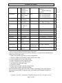
7E
7F
84
e
Bit 0: T1 force encrypt
Bit 1 : T2 force encrypt
Bit 2 : T3 force encrypt
Bit3 : T3 force encrypt when
card type is 0
Copyright © 2010-2013, International Technologies & Systems Corp. All rights reserved.
Page 31 of 40
SecuRED User Manual
EnStructID
85
MaskOptID
86
PwrStrDlyID*
87
HashTypeID
88
FixKeyLeverI
D
8A
WinCETestID
*
PrefixID
PostfixID
AddedFieldID
*
SearchCmdID
*
SendCmdID*
Encryption
‘0’,(‘0’-‘1’)
Structure
(Enhanced or
original)
Masked / clear 0x07
data sending
option
Reserved for
UNIMAG
Hash type
‘0’ (‘0’-‘1’)
selection
Review lever
‘1’(‘1’-‘3’)
of the Fix
key
A0
A1
AA
D2
D3
FA
FB
FC
‘0’ –Original Encrypt
Structure
‘1’ – Enhanced Encrypt
Structure
Bit0: T1 mask allowed
Bit1: T2 mask allowed
Bit2: T3 mask allowed
e
‘0’ – SHA-1 20 bytes
‘1’ - SHA-2 32 bytes
Value from ‘1’-‘3’
e
e
None
Preamble
Postamble
DE Added
Field
DE Search
Cmd
DE Send Cmd
0
0
0
No Preamble, 15 char max
No Postamble, 15 char max
No Added Field
d
0
No Search Command
d
08 00 FF 00 FF
00 FF 00 FF
0
No Send Command
d
SearchCmdID FD
DE Search
No Search Command2
2
Cmd 2
*Unused entries in this table were left for completeness even though unused in the Mag
reader to avoid conflicting definitions between products.
Note not all function ID are present in different hardware version of the SecuRED the last
column above has some codes:
‘-‘ feature not currently supported; exists for compatibility
‘s’ feature available on in the RS232 serial version of the reader
‘u’ feature available only in the USB version;
‘k’ feature available on in the keyboard version
‘p’ feature available only in the SPI version
‘r’ reset all does not affect this value
‘n’ not directly settable
‘d’ feature only for reader with data editing feature
‘e’ feature only for reader with encrypt feature
Most function ID settings that relate to the content of formatting of the track output do
not work in secure mode. Exceptions to this are Preamble and Postamble in keyboard
mode only.
Copyright © 2010-2013, International Technologies & Systems Corp. All rights reserved.
Page 32 of 40
d
SecuRED User Manual
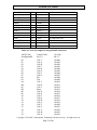
APPENDIX B ERROR CODE LIST TABLE
Order
Error code
Note
1
0xE0 00
2
0xE1 00
3
0xE2 00
4
0xE3 00
5
0xE4 00
6
0xE5 (ID code)
7
0xE6 (ID code)
8
0xE7 (ID code)
9
0xE8 00
Command length is error. ID code is
command ID.
Parameter is error. The parameter is out
scope.
Command is error. The device don’t
support the command.
Command LRC is error.
10
0xE9 00
Command time overflow.
11
0xEA 00
12
0xEB 00
Operation is error. It is often occured by
error operation order.
Random data don`t match.
13
0xEC 00
MSR key has existed.
14
0xED 00
MSR key don`t exist.
15
0xEE 00
Secure level don`t match requirement.
16
0xEF 00
EEPROM write error.
17
0x00 00
No error
No Card Account number(Paring key
part).
Paring key don’t exist. Operate related
command before loading Paring key.
Paring key has existed.
The parameter doesn’t match. Parameter
of the command doesn’t match
requirement.
Fail to decrypt data.
Copyright © 2010-2013, International Technologies & Systems Corp. All rights reserved.
Page 33 of 40
SecuRED User Manual
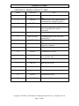
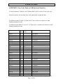
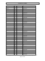
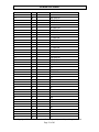
APPENDIX C Key Code Table in USB Keyboard Interface
For most characters, "Shift On" and "Without Shift" will be reverse if Caps Lock is on.
Firmware needs to check current Caps Lock status before sending out data.
For Function code B1 to BA, if "Num Lock" is not set, then set it and clear it after
finishing sending out code.
For Function code BB to C2, C9 to CC, if "Num Lock" is set then clear it and set it after
finishing sending out code.
Keystroke
Ctrl+2
Ctrl+A
Ctrl+B
Ctrl+C
Ctrl+D
Ctrl+E
Ctrl+F
Ctrl+G
BS
Tab
Ctrl+J
Ctrl+K
Ctrl+L
Enter
Ctrl+N
Ctrl+O
Ctrl+P
Ctrl+Q
Ctrl+R
Ctrl+S
Ctrl+T
Ctrl+U
Ctrl+V
Ctrl+W
Ctrl+X
Ctrl+Y
Ctrl+Z
Hex
Value
00
01
02
03
04
05
06
07
08
09
0A
0B
0C
0D
0E
0F
10
11
12
13
14
15
16
17
18
19
1A
Functional
Code
\bs
\tab
\enter
USB KB Code
1F Ctrl On
04 Ctrl On
05 Ctrl On
06 Ctrl On
07 Ctrl On
08 Ctrl On
09 Ctrl On
0A Ctrl On
2A
2B
0D Ctrl On
0E Ctrl On
0F Ctrl On
28
11 Ctrl On
12 Ctrl On
13 Ctrl On
14 Ctrl On
15 Ctrl On
16 Ctrl On
17 Ctrl On
18 Ctrl On
19 Ctrl On
1A Ctrl On
1B Ctrl On
1C Ctrl On
1D Ctrl On
Copyright © 2010-2013, International Technologies & Systems Corp. All rights reserved.
Page 34 of 40
SecuRED User Manual
ESC
Ctrl+\
Ctrl+]
Ctrl+6
Ctrl+SPACE
!
"
#
$
%
&
'
(
)
*
+
,
.
/
0
1
2
3
4
5
6
7
8
9
:
;
<
=
>
?
@
A
B
C
D
E
1B
1C
1D
1E
1F
20
21
22
23
24
25
26
27
28
29
2A
2B
2C
2D
2E
2F
30
31
32
33
34
35
36
37
38
39
3A
3B
3C
3D
3E
3F
40
41
42
43
44
45
\esc
29
31 Ctrl On
30 Ctrl On
23 Ctrl On
2D Ctrl On
2C
1E Shift On
34 Shift On
20 Shift On
21 Shift On
22 Shift On
24 Shift On
34
26 Shift On
27 Shift On
25 Shift On
2E Shift On
36
2D
37
38
27 Shift On
1E Shift On
1F Shift On
20 Shift On
21 Shift On
22 Shift On
23 Shift On
24 Shift On
25 Shift On
26 Shift On
33 Shift On
33
36 Shift On
2E
37 Shift On
38 Shift On
1F
04 Shift On
05 Shift On
06 Shift On
07 Shift On
08 Shift On
Copyright © 2010-2013, International Technologies & Systems Corp. All rights reserved.
Page 35 of 40
SecuRED User Manual
F
G
H
I
J
K
L
M
N
O
P
Q
R
S
T
U
V
W
X
Y
Z
[
\
]
^
_
`
a
b
c
d
e
f
g
h
i
j
k
l
m
n
o
p
46
47
48
49
4A
4B
4C
4D
4E
4F
50
51
52
53
54
55
56
57
58
59
5A
5B
5C
5D
5E
5F
60
61
62
63
64
65
66
67
68
69
6A
6B
6C
6D
6E
6F
70
09 Shift On
0A Shift On
0B Shift On
0C Shift On
0D Shift On
0E Shift On
0F Shift On
10 Shift On
11 Shift On
12 Shift On
13 Shift On
14 Shift On
15 Shift On
16 Shift On
17 Shift On
18 Shift On
19 Shift On
1A Shift On
1B Shift On
1C Shift On
1D Shift On
2F
31
30
23 Shift On
2D Shift On
35
04
05
06
07
08
09
0A
0B
0C
0D
0E
0F
10
11
12
13
Copyright © 2010-2013, International Technologies & Systems Corp. All rights reserved.
Page 36 of 40
SecuRED User Manual
q
r
s
t
u
v
w
x
y
z
{
|
}
~
DEL
F1
F2
F3
F4
F5
F6
F7
F8
F9
F10
F11
F12
Home
End
→
←
↑
↓
PgUp
PgDn
Tab
bTab
Esc
Enter
Num_Enter
Delete
Insert
71
72
73
74
75
76
77
78
79
7A
7B
7C
7D
7E
7F
81
82
83
84
85
86
87
88
89
8A
8B
8C
8D
8E
8F
90
91
92
93
94
95
96
97
98
99
9A
9B
\f1
\f2
\f3
\f4
\f5
\f6
\f7
\f8
\f9
\fa
\fb
\fc
\home
\end
\right
\left
\up
\down
\pgup
\pgdn
\tab
\btab
\esc
\enter
\num_enter
\del
\ins
14
15
16
17
18
19
1A
1B
1C
1D
2F Shift On
31 Shift On
30 Shift On
35 Shift On
2A
3A
3B
3C
3D
3E
3F
40
41
42
43
44
45
4A
4D
4F
50
52
51
4B
4E
2B
2B Shift On
29
28
58
4C
49
Copyright © 2010-2013, International Technologies & Systems Corp. All rights reserved.
Page 37 of 40
SecuRED User Manual
Backspace
SPACE
Pause
Ctrl+[
Ctrl+]
Ctrl+\
Left_Ctrl_Break
Left_Ctrl_Make
Left_Shift_Break
Left_Shift_Make
9C
9D
9C
9F
A0
A1
A2
A3
A4
A5
\bs
\sp
\ps
\ctr1
\ctr2
\ctr3
\l_ctrl_bk
\l_ctrl_mk
\l_shift_bk
\l_shift_mk
Left_Windows
Left_Alt_Break
Left_Alt_Make
Right_Ctrl_Break
Right_Ctrl_Make
Right_Shift_Break
Right_Shift_Make
A6
A7
A8
A9
AA
AB
AC
\l_windows
\l_alt_bk
\l_alt_mk
\r_ctrl_bk
\r_ctrl_mk
\r_shift_bk
\r_shift_mk
Right_Windows
Right_Alt_Break
Right_Alt_Make
Num_Lock
Num_0
Num_1
Num_2
Num_3
Num_4
Num_5
Num_6
Num_7
Num_8
Num_9
Num_Home
Num_PageUp
Num_PageDown
Num_End
Num_↑
Num_→
Num_↓
Num_←
AD
AE
AF
B0
B1
B2
B3
B4
B5
B6
B7
B8
B9
BA
BB
BC
BD
BE
BF
C0
C1
C2
\r_windows
\r_alt_bk
\r_alt_mk
\num_lock
\num0
\num1
\num2
\num3
\num4
\num5
\num6
\num7
\num8
\num9
\num_home
\num_pgup
\num_pgdn
\num_end
\num_up
\num_right
\num_down
\num_left
2A
2C
48
2F Ctrl On
30 Ctrl On
31 Ctrl On
Clear Ctrl Flag
Set Ctrl Flag for following char(s)
Clear Shift Flag
Set Shift Flag for following
char(s)
E3 (left GUI)
Clear Alt Flag
Set Alt Flag for following char(s)
Clear Ctrl Flag
Set Ctrl Flag for following char(s)
Clear Shift Flag
Set Shift Flag for following
char(s)
E7 (right GUI)
Clear Alt Flag
Set Alt Flag for following char(s)
53
62 Num Lock On
59 Num Lock On
5A Num Lock On
5B Num Lock On
5C Num Lock On
5D Num Lock On
5E Num Lock On
5F Num Lock On
60 Num Lock On
61 Num Lock On
5F
61
5B
59
60
5E
5A
5C
Copyright © 2010-2013, International Technologies & Systems Corp. All rights reserved.
Page 38 of 40
SecuRED User Manual
Print_Scrn
System_Request
Scroll_Lock
Pause
Break
Caps_Lock
Num_/
Num_*
Num_Num_+
Num_.
Num_DEL
Num_INS
Delay_100ms
C3
C4
C5
C6
C7
C8
C9
CA
CB
CC
CD
CE
CF
D0
\prt_sc
\sysrq
\scroll
\menu
\break
\caps_lock
\num_/
\num_*
\num_\num_+
\num_.
\num_del
\num_ins
\delay
46
9A
47
76
39
54
55
56
57
63 Num Lock On
63
62
Delay 100 ms
Table of Ctrl or Alt output for non printable characters
ASCII Code
SendOptionID
00:
01:
02:
03:
04:
05:
06:
07:
08:
09:
0A:
0B:
0C:
0D:
0E:
0F:
10:
11:
12:
13:
14:
15:
16:
17:
18:
Control Code
Bit 3: 0
Ctrl-2
Ctrl-A
Ctrl-B
Ctrl-C
Ctrl-D
Ctrl-E
Ctrl-F
Ctrl-G
BS
Tab
Ctrl-J
Ctrl-K
Ctrl-L
Enter
Ctrl-N
Ctrl-O
Ctrl-P
Ctrl-Q
Ctrl-R
Ctrl-S
Ctrl-T
Ctrl-U
Ctrl-V
Ctrl-W
Ctrl-X
Alt Code
Bit 3: 1
Alt-000
Alt-001
Alt-002
Alt-003
Alt-004
Alt-005
Alt-006
Alt-007
Alt-008
Alt-009
Alt-010
Alt-011
Alt-012
Alt-013
Alt-014
Alt-015
Alt-016
Alt-017
Alt-018
Alt-019
Alt-020
Alt-021
Alt-022
Alt-023
Alt-024
Copyright © 2010-2013, International Technologies & Systems Corp. All rights reserved.
Page 39 of 40
SecuRED User Manual
19:
1A:
1B:
1C:
1D:
1E:
1F:
Ctrl-Y
Ctrl-Z
ESC
Ctrl-\
Ctrl-]
Ctrl-6
Ctrl--
Alt-025
Alt-026
Alt-027
Alt-028
Alt-029
Alt-030
Alt-031
Copyright © 2010-2013, International Technologies & Systems Corp. All rights reserved.
Page 40 of 40