1
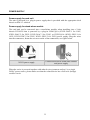
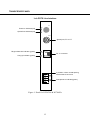
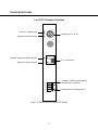
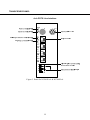
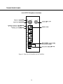
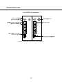
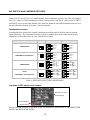
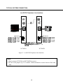
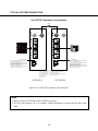
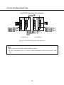
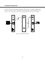
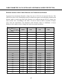
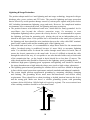
Tel: 1-888-685-2002 (toll-free, USA) 1-732-355-9100 Fax: 1-732-355-9101 E-mail: [email protected] Digital eight video channels with two DIP selectable data and Ethernet signal 51 Stouts Lane, Monmouth Junction, NJ 08852, U.S.A. FIBER OPTIC TRANSMISSION SYSTEM N3786 & N3586 SERIES Digital POTS Telephone and Modem Interface User Manual V2.7 1303 Infinova Contents SERVICE NOTICE ............................................................................................................... 1 PRODUCT DESCRIPTION.................................................................................................. 2 ORDERING INFORMATION .............................................................................................. 3 INSTALLATION................................................................................................................... 3 POWER SUPPLY.................................................................................................................. 5 TRANSCEIVER PANEL ...................................................................................................... 6 1-ch POTS Line Interface.............................................................................................. 6 1-ch POTS Telephone Interface..................................................................................... 7 4-ch POTS Line Interface.............................................................................................. 8 4-ch POTS Telephone Interface..................................................................................... 9 8-ch POTS Line Interface............................................................................................ 10 8-ch POTS Telephone Interface................................................................................... 11 DIP SWITCH AND JUMPERS SETTINGS ....................................................................... 12 TYPICAL SYSTEM CONNECTION ................................................................................. 13 1-ch POTS Telephone Line Interface .......................................................................... 13 4-ch POTS Telephone Line Interface .......................................................................... 14 8-ch POTS Telephone Line Interface .......................................................................... 15 TRANSMISSION REPEATER ........................................................................................... 16 CABLE DIAMETER CALCULATION AND LIGHTNING & SURGE PROTECTION .. 17 SERVICE NOTICE The installation of this product should be made by qualified personnel. Do not attempt to service this product yourself. Refer all servicing to qualified personnel. If you require information during installation of this product or if service seems necessary, contact the local suppliers or Infinova at 1-732-355-9100 in 51 Stouts Lane, Monmouth Junction, NJ 08852 U.S.A. You must obtain a Return Authorization Number and shipping instructions before returning any product for service. Our obligation under this warranty is limited only to the repair or replacement of any of our products, provided that products are used within the specified ratings and applications, and that products are applied in accordance with good engineering practices, and that products are proved by our examination to be defective. This warranty does not extend to any Infinova products which have been subject to acts of accident, misuse, abuse, neglect, improper application or installation, improper operation or maintenance, connection to an improper voltage supply or to materials which have been altered or repaired outside an authorized Infinova factory repair center. Information provided by Infinova is accurate and reliable. However, no responsibility is assumed by Infinova for its use; nor for any infringements of other rights of third parties which may result from its use. No license is granted by implications or otherwise under any patent or patent rights of Infinova. WARNING TO REDUCE THE RISK OF FIRE OR SHOCK HAZARD, DO NOT EXPOSE THIS PRODUCT TO RAIN OR MOISTURE. DO NOT LOOK INTO OPTICAL PORTS WITH POWER ON. 1 PRODUCT DESCRIPTION Description The N3786 and N3586 series provide high quality reliable transmission of digitally encoded POSTS Telephone and one bi-directional data over one or two optical fibers. N3786XA / XB shall convert one Telephone audio from source to Digitally Encoded light to transmit on fiber. N3786XA is compatible with N3786XB-M modules and N3786XB-R card units. Plug-and-play design ensures ease of installation requiring no electrical or optical adjustments. Each transmitter or receiver incorporates status indicators for monitoring of proper system operation. The modules are available in either stand-alone or card unit transmitter versions. Stand-alone module Card unit The N3786 series are compatible with 9/125micron single-mode fibers; the N3586 series are compatible with 50/125 or 62.5/125micron multimode fibers. Accessories (optional) N3910-000 19″ 1U fan assembly unit N3951 Fiber optical transmission repeater System Diagram 2 ORDERING INFORMATION Fiber Type Product Type 35 Multimode XA POTS Line Transceiver 37 Singlemode XB POTS Telephone Transceiver No. of Fibers No. of Audio Enclosure 2F 2 Fibers 1 channel M Stand-alone module Omit for 1 Fiber 4 channel R Card unit 8 channel Use the Configuration chart below to select the options available for this product. Note: The transmission distance category is valid for single-mode product only. INSTALLATION Installation of Series POTS Telephone and Modem Interface To install the apparatus, it is necessary to allow enough space to accommodate the bend radius of the optical cable connected to it. Series POTS Telephone and Modem Interface input/output use RJ11 connector and 4-pin terminal block connector of the data. Installation of card unit Push the card unit along the guide rails (not in spaces between the rails). There is an Infinova logo on the front panel indicating the proper orientation. Press hard to make good connection to motherboard - loud snap indicates firm connection. There are two captive screws on the front panel that can fasten the card unit to the subrack. They must be locked by hand in a clockwise manner (do not over tighten), see figure right below. Full load of N3910-18S There are 18 slots on N3910-18S. So it can mount 18 pieces of card unit. Besides N3910-18S, there are N3910-1S, N3910-2S, N3910-3S, N3910-4S and N3910-15R optional. There are 1 slot on N3910-1S, 2 slots on N3910-2S, 3 slots on N3910-3S, 4 slots on 3 N3910-4S and 15 slots on N3910-15R respectively. N3910-2S N3910-4S N3910-15R (Redundant power supply) WARNING: A FULL LOAD OF N3910-15R AND N3910-18S SUBRACK REQUIRES FORCED AIR COOLING IN THE RACK. TO AVOID OVER HEATING OF CARD UNITS, WHENEVER POSSIBLE, INSTALL IN EVERY OTHER SUBRACK. Forced air cooling 4 POWER SUPPLY Power supply for card unit The unit is powered by a plug-in power supply that is provided with the appropriate desk chassis or EIA 19″ subrack. Power supply for stand-alone module The card unit can be converted into a stand-alone module when installing into a 2-slot chassis N3910-2S that is powered by a plug-in 24VAC@1A (N3921-24AC-1 for 110V; N3921-24AC-2 for 220V; N3921-24AC-3 for 230V) or 12VDC@1A (N3921-12DC-1 for 110V; N3921-12DC-2 for 220V; N3921-12DC-3 for 230V) power supply. Plug the wires into the connectors, fasten the screws to make a firm connection, see figure below. Connection between stand-alone module and power supply N3921 power supply When the series is powered together with other devices (cameras and etc.) by a single 24VAC power source, please make sure that the related device has a full-wave (bridge) rectifier circuit. 5 TRANSCEIVER PANEL 1-ch POTS Line Interface Power on indicator(red) Optical loss indicator(red) IN PWR OP OUT Optical port, FC or ST Ringers detection indicator (green) Hang up indicator (green) T RJ-11 connector R 4-position 3.5mm central spacing terminal block connecotr 1 2 3 Data presence indicator(green) 4 Figure 1. Panel for N3586XA & N3786XA 6 TRANSCEIVER PANEL 1-ch POTS Telephone Interface Power on indicator(red) Optical loss indicator(red) IN PWR Optical port, FC or ST OP OUT Ringers detection indicator (green) Hang up indicator (green) T RJ-11 connector R 4-position 3.5mm central spacing terminal block connecotr 1 2 3 Data presence indicator(green) 4 Figure 2. Panel for N3586XB & N3786XB 7 TRANSCEIVER PANEL 4-ch POTS Line Interface Figure 3. Panel for N3586XA-4 & N3786XA-4 8 TRANSCEIVER PANEL 4-ch POTS Telephone Interface Figure 4. Panel for N3586XB-4 & N3786XB-4 9 TRANSCEIVER PANEL 8-ch POTS Line Interface Figure 5. Panel for N3586XA-8 & N3786XA-8 10 TRANSCIVER PANEL 8-ch POTS Telephone Interface Figure 6. Panel for N3586XB-8 & N3786XB-8 11 DIP SWITCH AND JUMPERS SETTINGS Jumper of JP2 on N3786 is to enable/disable line termination resistor. Set JP2 with jumper cap is to connect 120Ω termination resistor between Pin3 and Pin 4. DIP switch of DIP-1 and DIP-2 are to set the data format; they must be identical on both transmitter and receiver for specified data format. See table 1 for more details. Termination resistor A multipoint bus architecture requires termination at both ends of the bus line to restrain signal reflection. The termination resistors must be within 20 percent of the characteristic impedance of the cable and can vary from 90 Ω to 120 Ω. 2-WIRE RS485 ON 1 2 1 2 ON RS422/Manchester/Biphase XB 1 2 ON 4-WIRE RS485 DIP ON Data format 1 Return RS422/Manc hester/Biphase 2 XA Data out + Data out - Data out + Data out - Data in + Data in - Data in + Data in - Data out + Data out + Data out Data in + Data out Data in + Data in - Data in - Data + CH1 Data - Data + CH1 Data - Data + CH2 Data - Data + CH2 Data - Data out + Data In + Data In - CH1 Data In + CH2 Data In - CH1 Data out Data out + CH2 Data out - Table 1. DIP SWITCH SETTING REFERENCE Location of DIP switch and Jumper: DIP s witch for Da ta Format Setting JP2 for termination resistor setting For the detailed location of the DIP switch on transceiver, please refer to TRANSMITTER PANEL and RECEIVER PANEL 12 TYPICAL SYSTEM CONNECTION 1-ch POTS Telephone Line Interface N3786XA N3786XB Figure 7. 1-ch POTS Telephone Line Interface Note: 1. Don’t connect N3786XA and N3786XB in reverse. 2. Set JP2 with jumper cap is to connect 120Ω termination resistor between Pin3 and Pin4. 13 TYPICAL SYSTEM CONNECTION 4-ch POTS Telephone Line Interface Fiber PWR IN PWR OUT ..... ..... ..... T T R R T T R R ..... T T .... R R T T R R Telephone Switch System 4-PIN CONNECTOR 1#: CH.1 MANCHESTER IN+/ 2-wire RS-485 D+ OR RS-422 / 4-wire RS-485 OUT+ 2#: CH.1 MANCHESTER IN-/ 2-wire RS-485 DOR RS-422 / 4-wire RS-485 OUT3#: CH.2 MANCHESTER IN+/ 2-wire RS-485 D+ OR RS-422 / 4-wire RS-485 IN+ 4#: CH.2 MANCHESTER IN-/ 2-wire RS-485 DOR RS-422 / 4-wire RS-485 IN- IN OUT OP OP 1 1 2 2 3 3 4 4 Telephone 4-PIN CONNECTOR 1#: CH.1 MANCHESTER OUT+/ 2-wire RS-485 D+ OR RS-422 / 4-wire RS-485 OUT+ 2#: CH.1 MANCHESTER OUT-/ 2-wire RS-485 DOR RS-422 / 4-wire RS-485 OUT3#: CH.2 MANCHESTER OUT+/ 2-wire RS-485 D+ OR RS-422 / 4-wire RS-485 IN+ 4#: CH.2 MANCHESTER OUT-/ 2-wire RS-485 DOR RS-422 / 4-wire RS-485 IN- INSIDE 4-POSITION DIP SWITCH DIP-1 OFF & DIP-2 OFF : 1- ch 4-wire full duplex RS-485 available DIP-1 OFF & DIP-2 ON : 1-ch RS-422 data available DIP-1 ON & DIP-2 OFF : 2- ch 2-wire half duplex RS-485 (default setting) DIP-1 ON & DIP-2 ON : 2- ch return Manchester data DIP-3 OFF: N/A DIP-4 OFF: N/A N3786XA-4 N3786XB-4 Figure 8. 4-ch POTS Telephone Line Interface Note: 1. Don’t connect N3786XA and N3786XB in reverse. 2. Set JP2 with jumper cap is to connect 120Ω termination resistor between Pin3 and Pin4. 14 TYPICAL SYSTEM CONNECTION 8-ch POTS Telephone Line Interface N3786XA-8 N3786XB-8 Figure 9. 8-ch POTS Telephone Line Interface Note: 1. Don’t connect N3786XA and N3786XB in reverse. 2. Set JP2 with jumper cap is to connect 120Ω termination resistor between Pin 3 and Pin4. 15 TRANSMISSION REPEATER The N3951 series is used between transmitter and receiver to extend the transmission distance of fiber optical system. It magnifies the optical signal received from transmitter, and sends it to receiver. By using a N3951, the transmission distance of the system is doubled. PWR IN OUT .... .... .... .... .... Telephone Switch System PWR O U T OP IN OP Fiber OUT T T Fiber R R Telephone 1 I N 1 3 2 3 4 4 2 N3786XA N3951 Figure 10. Transmission repeater 16 N3786XB CABLE DIAMETER CALCULATION AND LIGHTNING & SURGE PROTECTION Relation between 24VAC Cable Diameter and Transmission Distance In general, the maximum allowable voltage loss rate is 10% for AC-powered devices. The table below shows the relationship between transmission power and maximum transmission distance under a certain specified cable diameter, on condition that the 24VAC voltage loss rate is below 10%. According to the table, if a device rated at 50W is installed 17-meter away from the transformer, the minimum cable diameter shall be 0.8000mm. A lower diameter value tends to cause voltage loss and even system instability. Diameter (mm) 0.8000 1.000 1.250 2.000 10 283 (86) 451 (137) 716 (218) 1811 (551) 20 141 (42) 225 (68) 358 (109) 905 (275) 30 94 (28) 150 (45) 238 (72) 603 (183) 40 70 (21) 112 (34) 179 (54) 452 (137) 50 56 (17) 90 (27) 143 (43) 362 (110) 60 47 (14) 75 (22) 119 (36) 301 (91) 70 40 (12) 64 (19) 102 (31) 258 (78) 80 35 (10) 56 (17) 89 (27) 226 (68) 90 31 (9) 50 (15) 79 (24) 201 (61) 100 28 (8) 45 (13) 71 (21) 181 (55) 110 25 (7) 41 (12) 65 (19) 164 (49) 120 23 (7) 37 (11) 59 (17) 150 (45) 130 21 (6) 34 (10) 55 (16) 139 (42) 140 20 (6) 32 (9) 51 (15) 129 (39) 150 18 (5) 30 (9) 47 (14) 120 (36) 160 17 (5) 28 (8) 44 (13) 113 (34) 170 16 (4) 26 (7) 42 (12) 106 (32) 180 15 (4) 25 (7) 39 (11) 100 (30) 190 14 (4) 23 (7) 37 (11) 95 (28) 200 14 (4) 22 (6) 35 (10) 90 (27) Distance (ft / m) Power (W) 17 Lightning & Surge Protection The product adopts multi-level anti-lightning and anti-surge technology integrated with gas discharge tube, power resistor and TVS tube. The powerful lightning and surge protection barrier effectively avoids product damage caused by various pulse signals with power below 4kV, including instantaneous lightning, surge and static. However, for complicated outdoor environment, refer to instruction below for lightning and surge protection: The product features with dedicated earth wire, which must be firmly grounded. As for surveillance sites beyond the effective protection scope, it’s necessary to erect independent lightening rods to protect the security devices. It’s recommended to separate the lightning rod from the mounting pole, placing the rod on an independent pole, as shown in the figure below. If the product has to be installed on the same pole or pedestal for lightning rod, there should be strict insulation between the video cable BNC terminal, power cable, control cable and the standing pole of the lightning rod. For suburb and rural areas, it’s recommended to adopt direct burial for the transmission cables. Overhead wiring is prohibited, because it’s more likely to encounter lightning strike. Use shielded cables or thread the cables through metal tubes for burial, thus to ensure the electric connection to the metal tube. In case it’s difficult to thread the cable through the tube all the way, it’s acceptable to use tube-threaded cables only at both ends of the transmission line, yet the length in burial should be no less than 15 meters. The cable sheath and the tube should be connected to the lightning -proof grounding device. Additional high-power lightning-proof equipment and lightning rods should be installed for strong thunderstorm or high induced voltage areas (such as high-voltage substation). The lightning protection and grounding for outdoor devices and wires should be designed in line with the actual protection requirement, national standards and industrial standards. The system should perform equipotential grounding by streaming, shielding, clamping and earthing. The grounding device must meet anti-interference and electric safety requirements. There should be no short-circuiting or hybrid junction between the device and the strong grid. Make sure there’s a reliable grounding system, with grounding resistance below 4Ω (below 10Ω for high soil resistivity regions). The cross-sectional area of the earthing conductor should be no less than 25mm². LPZOA 30° 30° Lightning rod LPZOB Front device for surveillance system Mounting pole for front device Separated layout for the lightning rod and the standing pole 18 FIBER OPTIC TRANSMISSION SYSTEM 51 Stouts Lane, Monmouth Junction, NJ 08852, U.S.A. Tel: 1-888-685-2002 (toll-free, USA) 1-732-355-9100 Fax: 1-732-355-9101 N3729 SERIES Digital One Video Channel with Return Data E-mail: [email protected] User Manual V2.1 1401 Infinova