1
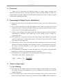
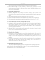
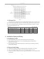
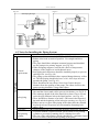
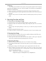
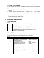
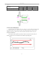
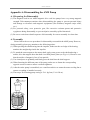
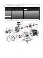
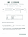
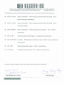
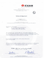
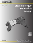
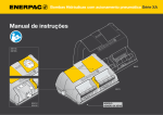
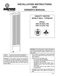
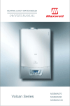
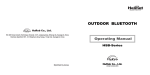
AMX
SERIES
MAGNETICALLY DRIVEN CHEMICAL PUMP
USER MANUAL
AMX SERIES
Table of Contents
1.Foreword …………………………………………………………………………….…….. 2
2.Inspecting the Pump Prior to Installation …………………………………………………. 2
3.Notes for Operation ……………………………………………………………………….. 2
3.1 Dry-Running ……………………………………………………………………….. 2
3.2 Operating Temperature …………………………………………………………….. 3
3.3 Concentrations, Viscosity and Specific Gravity ………………………………….... 3
3.4 Particle Size (Sludge) …………………………………………………………...…. 3
3.5 Maximum Operating Pressure …………………………………………………..…. 3
3.6 Minimum Flow ………………………………………………………………….…. 4
4.Installation, Piping and Wiring ……………………………………………………………. 4
4.1 Installation Location …………………………………………………….…………. 4
4.2 Inlet and Outlet Piping …………………………………………………………..…. 4
4.3 Notes for Installing the Piping System …………………………………………….. 5
4.4 Wiring …………………………………………………………………………….... 8
5.Operating Procedure and Notes …………………………………………………………… 8
5.1 Notes Prior to Starting the Pump ………………………………………………..…. 8
5.2 Starting Up the Pump …………………………………………………………...…. 8
5.3 Operating the Pump ……………………………………………………………..…. 8
5.4 Shutting Down the Pump ………………………………………………….…….…. 9
6.Maintenance and Inspection ………………………………………………………………. 9
6.1 Daily Inspection ……………………………………………………………………. 9
6.2 Periodic Maintenance …………………………………………………………….... 9
6.3 Preventive Maintenance ………………………………………………………….... 10
7.Incorrect Usage and Selection …………………………………………………………….. 11
8.Repair and Warranty ………………………………………………………………………. 12
Appendix A: Disassembling the AMX Pump ……………………………………………….. 13
A.1 Preparing for Disassembly …………………………………………………………..…. 13
A.2 Assembly ………………………………………………………………………………. 13
Appendix B: Parts List and Exploded View ………………………………………………… 14
1
AMX SERIES
1. Foreword
Thank you for purchasing an ASSOMA pump. To ensure proper operation and
maximum efficiency, please read this instruction manual carefully. Failure to follow the
recommended operating conditions outlined in this manual may result in serious personal
injuries and/or equipment damage.
2. Inspecting the Pump Prior to Installation
(1) Check the pump exterior for any physical damage that may have been incurred during
shipping.
(2) Use a small screwdriver to rotate the impeller of the motor’s cooling fan. The fan
should turn easily. If the fan feels tight or if there are unusual sounds, the interior of the
pump may have been damaged during shipping.
(3) If there is any damage to the pump, contact the shipping company and the distributor
immediately to determine who should pay for the damage, and to arrange for
replacement parts.
(4) Each pump has a nameplate, indicating the pump model, MFG number, rated head,
flow rate, motor power, voltage and frequency. Check these data to ensure they comply
with your order and application.
(5) When using versatile motor with 50Hz and 60Hz compliance, be sure to use suitable
diameter of impeller according to the frequency of power. A wrong diameter can cause
the motor overload (frequency is too high) or insufficient pump performance
(frequency is too low).
(6) The information of nameplates on motor and pump is key for operation setup and pump
maintenance. Please keep the nameplate intact for reference.
(7) The nameplate of a pump indicates the optimum point of its operation. Therein,
Total Head= Static Head + Dynamic Head.
V 2 − V1 2
Head = H s +
2g
2
Total
3. Notes for Operation
3.1 Dry-Running
(1) Our pump use the transfer fluid as its internal cooling system, therefore, dry-running
the pump can cause the temperature to rise to a dangerous level that may seriously
damage the pump.
(2) If dry-running occurs, switch off the pump immediately, let it cool for at least an hour
before priming the pump to prepare it for normal operation. NOTE: Do not subject the
2
AMX SERIES
pump to rapid cooling, which may damage the internal parts (thermal shock).
(3) We recommend using a dry-run protector to detect dry-run occurrences to avoid
causing unnecessary damage to the pump. Please contact ASSOMA distributor near
your area for such apparatus.
3.2 Operating Temperature
(1) Operating temperature may change the fluid’s viscosity, vapor pressure, and
corrosiveness. Please ensure that your pump is operating within the proper temperature
range.
o
o
(2) The optimal temperature range for pumping pure water is 5 C~80 C.
(3) Please consult the distributor for the temperature range suitable for your chemicals.
o
o
(4) We recommend the operating environmental temperature to be between 5 C~40 C.
3.3 Concentrations, Viscosity and Specific Gravity
(1) A change in a fluid’s concentration will usually affect its viscosity and specific gravity.
Other physical properties like corrosiveness, may also change with the fluid’s
concentration, therefore, the selected pump material should be able to withstand the
corrosive properties of the fluid.
(2) When the fluid’s viscosity and/or specific gravity differ from that of water, the shaft
power, flow rate and pump head may change also.
3.4 Particle Size (Sludge)
(1) In principle, it is not recommended to carry fluid with small particles. The service life
of a pump can be greatly shortened by pumping fluids that carry small particles or
sludge. Its service life is dependent on the concentration of the particles, its size, and
hardness.
(2) For particle concentration less than 5%, particle size smaller than 50μm, and hardness
within 80Hs, our SV model, which has SiC bushings, can be used. However, a
shorter-than-normal service life can be expected.
3.5 Maximum Operating Pressure
The pump’s maximum operating pressure is dependent on the operating temperature
and the structure of the pump. Please refer to figure 3.1 for the recommended maximum
operating pressure for our AMX SERIES pumps.
3
AMX SERIES
Fig. 3.1
AMX-545/543/542
3.6 Minimum Flow
Our pump uses the pumped fluid as its cooling and lubricating system. A low flow rate
may result in increasingly high temperature within the pump, and increased radial and axial
force, thus, affecting the pump’s performance and service life. Please use table 3.1 for the
recommended minimum flow rate:
Table 3.1
o
Operating Temperature C
AMX-655/653
AMX-555/545
AMX-553/552/543/542
AMX-441/440
20
50
30
20
15
40
50
30
20
15
60
70
40
30
20
Unit: Liter/min
80
100
50
40
30
Note: The above data is based on water. For volatile or viscous fluids, consult your local distributor.
4. Installation, Piping and Wiring
4.1 Installation Location
(1) The pump should be close to the ground and located near the inlet tank.
(2) There should be sufficient space reserved around the pump to facilitate future
maintenance and repairs.
(3) The pump and its wiring should be placed in a relatively dry environment, protected
from possible flooding.
4.2 Inlet and Outlet Piping
(1) AMX RF type flange is flexible for piping assembly with rotatable screw holes.
(2) The screw for AMX flange is M16 or 5/8”. The torque required is 5 N-m.
(3) The pipes should have adequate structural support and shouldn’t over its allowable load
on the pump.
4
AMX SERIES
Fig. 4.1
Z
Y
X
Z
X
Y
SUCTION
Flange Size
Fx
120
120
150
40A
50A
65A
Force (N)
Fy
Fz
100
100
100
100
120
120
ΣF
180
180
200
Mx
20
30
30
ΣF<180
Moment (N-m)
My
Mz
30
20
50
30
50
30
ΣM
60
75
75
ΣM<75
DISCHARGE
Flange Size
Fx
100
120
40A
50A
Force (N)
Fy
Fz
120
100
150
120
ΣF
180
200
Mx
20
30
Moment (N-m)
My
Mz
30
20
50
30
ΣM
60
75
※ Note: The above data is based on operating temperature under 40℃.
Fig. 4.2
Fig. 4.3
1.Outlet Piping
2.Throttle Valve
3.Priming Piping
4.Priming Valve
5.Check Valve
3
6.Outlet Pressure Gauge
4
7.Motor
8.Pump
9.Inlet Pressure Gauge
10.Inlet Piping
9
11.Inlet Piping Support
11
12.Vibration Damper
10
13.Filter
14.Inlet Tank
13
12
15.Foot Valve
14
1
Bad
2
5
8
6
7
0.01~0.02 slope
15
5
Good
AMX SERIES
Fig.4.4
Fig.4.5
Bad Piping Designs
>0.5m
or
>2D
>1.5D
D=Diameter
>1.5D
4.3 Notes for Installing the Piping System
Procedure
Inlet Piping
General
requirements
Inlet piping
Foot valve
Self-priming
cylinder
Items to Note
1. Suction condition must satisfy NPSHa>NPSHr+0.5m
2. Reduce inlet head as much as possible. Use straight and short
piping.
3. The pipes should have adequate structural support and shouldn’t
use the pump as its primary support. (see Fig. 4.2)
4. When designing supports, consider the effects of temperature
changes on the supports to avoid thermal stress.
5. Inlet piping and connectors should be installed properly to prevent
sucking in air. (see Fig. 4.4)
6. The piping system should not have upward bumps that may collect
air. The inlet piping should also have a 0.01~0.02 slope increase
towards the pump. (see Fig. 4.3)
7. There should not be any elbows for at least 5 times the pipe
diameter from the opening of the pump. The elbow closest to the
pump opening should be a long radial elbow.
1. There should be at least a 1.5 diameter distance between the pipe
inlet and the closest tank wall to prevent circulation. (see Fig. 4.5)
2. The submerge depth of the inlet should be at least 0.5m or at least
twice the pipe diameter below the liquid surface. (see Fig. 4.5)
3. There should be a distance of at least 1.5D between the bottom of
the tank and the beginning of the inlet pipe opening. (see Fig. 4.5)
4. If there are two or more inlet piping in the same tank, they should
be placed at least 3D apart to prevent mutually disrupting each
other’s flow.
1. Please install a foot valve if upward suction is used. (see Fig. 4.2)
1. If suction method is upward suction, please install a self-priming
cylinder to prevent dry-running due to a leaking foot-valve.
2. The size of the self-priming cylinder should have a minimum liquid
level of at least 0.5m above the opening of the pump.
6
AMX SERIES
Control valve
Filter
Vacuum gauge
General
requirements
Outlet Piping
Priming piping
Pressure gauge
Check valve
Control valve
Exhaust valve
1. A control valve should be installed to make disassembling of the
pump easier. The valve should only be shut off when the pump is to
be detached for maintenance or repairs.
2. We recommend the use of valves that have the least loss when fully
opened, like a gate valve.
1. It is generally not recommended to install a filter in front of a
pump, which can unpredictably increase suction system resistance.
2. If a filter has to be used, it should be cleaned regularly to ensure a
smooth flow.
1. The material used should be corrosion resistant, otherwise, a
pressure gauge diaphragm should be used.
2. During operation, if the vacuum gauge reading fluctuates, either
there are air bubbles in the system or cavitation has occurred.
1. The weight of the outlet piping should be properly supported to
prevent putting excessive stress on the pump. (see Fig. 4.2)
2. A priming piping must be installed if the suction system does not
employ positive pressure, i.e. upward suction. (see Fig. 4.2)
3. The flow rate in the outlet piping should not exceed 3m/sec.
4. The ability for each component in the piping system to withstand
pressure should be calculated, to determine the maximum
allowable operating pressure.
1. Upward suction pumps that do not have a self-priming cylinder
should have a priming piping system.
1. Pressure gauge used should be able to read beyond the maximum
operating pressure.
2. Pressure gauge should be made of material that is corrosive
resistant, otherwise a diaphragm should be used.
3. A valve can be installed on the piping that leads to the pressure
gauge, to facilitate maintenance and to lengthen the gauge’s service
life.
4. During operation, if the pressure gauge reading fluctuates, either
there are air bubbles in the system or cavitation has occurred.
A check valve should be installed in the following situations:
1. Discharge pressure exceeds 1.5kg/cm2 and flow rate exceeds
2.5m/sec.
2. Two or more pumps share the same outlet piping system.
3. To prevent back flow (water hammer) from damaging the pump
during unexpected power outages.
1. A control valve can be used for controlling the flow of fluids. Do
not run the pump with the control valve closed for an extended
period of time.
2. When starting the pump, always start with a closed valve, and then
slowly open the valve to obtain the desired operating pressure and
flow. Always open or close the valve gradually.
1. A vent should be installed if the horizontal section of the outlet
piping is very long.
7
AMX SERIES
4.4 Wiring
The wiring system should be done properly, using premium equipment and complying
with rules and standards set by the electrical company. The following recommendations
should also be implemented:
(1) Please use magnetic relays that have the same power ratings as the pump’s motor.
(2) When using the pump for outdoor applications, please make sure the switch is protected
from rain.
(3) Magnetic relays and on-off switches should be installed properly and away from the
pump.
5. Operating Procedure and Notes
5.1 Notes Prior to Starting the Pump
(1) Check the motor’s power rating, including frequency, voltage and wiring.
(2) Recheck to make sure all the parts (flange, pump casing, base plate, etc.) are securely
fastened.
(3) Fill the pump with liquid (priming) to remove any air within the pump and suction
piping.
(4) Check to ensure the inlet valve is open.
(5) Using a screwdriver, rotate the motor’s cooling fan to ensure it is not too tight or stuck.
5.2 Starting Up the Pump
(1) Check the direction of rotation of the motor by rapidly switching on and off the power.
(2) Close the outlet valve and start up the pump.
(3) Slowly open the outlet valve when the motor has reached a stable speed. Adjust the
outlet valve to obtain the desired operating pressure or flow rate.
5.3 Operating the Pump
(1) Shut down the pump immediately in the case of cavitation or dry-running.
(2) If decoupling should happen, shut down the pump to prevent reducing the magnet’s
strength.
(3) During power outages, shut off the pump’s power supply and close the outlet valve.
(4) When switching on the pump with the outlet valve closed, the outlet pressure should
increase. If the pressure fails to rise, or if the pressure is too low, shut down the pump
and check the piping and wiring.
NOTE:
Outlet Pressure = Inlet Pressure + Pump Pressure
Pump Pressure (kg/cm2) = Fluid Specific Gravity * Pump Head / 10
8
AMX SERIES
5.4 Shutting Down the Pump
(1) Close the outlet valve slowly to prevent damage to the pump due to reverse fluid flow
(water hammer).
(2) Shut off the pump. It should stop gradually. If not, check the interior of the pump for
problems.
(3) The pump should be checked periodically. If the pump is used in a cold operating
environment (relative to the fluid’s freezing point), the fluid may crystallize even if the
pump is shut down for a very short amount of time. To prevent crystallization, a drain
plug should be included in the piping system or a heating system could be used to
maintain the temperature during shutdown.
6. Maintenance and Inspection
6.1 Daily Inspection
Table 6.1
Appearance
Operation
1. Check for oxidation or corrosion of the front casing, bracket, and base
plate.
2. Check for leakage of the pump and the piping system.
1. Check for irregular sounds and vibrations.
2. Check the in-tank fluid levels and inlet/outlet pressures.
3. Check the power supply and motor loading.
4. Check and test-run backup pumps regularly to ensure they can
function properly when needed.
6.2 Periodic Maintenance
(1) The following parts (see Table 6.2) should be inspected quarterly.
(2) Disassembling, assembly and precautions please refer to Appendix A.
Table 6.2
Part Name
Front and
rear casing
Front casing
o-ring
Inspection Item
Solution
1. Cracks.
1. Replace.
2. Scratch marks (except when pumping 2. Contact the distributor.
particle laden fluids).
3. Crystallization or sludge.
3. Clean.
4. Shaft support loose or deformed.
4. Contact distributor.
1. Deformed, corroded or swollen.
1. Scratch marks or cracks.
2. Cracked bearing or crystallization.
Impeller and
3. Bearing displays signs of some wear
magnet
and tear.
assembly
4. Crystallization and other sludge.
5. Foreign objects stuck in impeller.
6. Impeller deformed.
Shaft and thrust 1. Scratch marks.
ring
2. Cracks.
9
1. Replace.
1. Contact distributor.
2. Contact distributor.
3. Replace if worn
excessively.
4. Clean.
5. Remove the objects.
6. Contact distributor.
1. Contact distributor.
2. Replace.
AMX SERIES
Table 6.3
Wear limit
Thickness upon shipment
Thickness upon replacement
AMX-440/441
A(mm)
D(mm)
6
15
<5
>15.5
AMX-552/553/555/653/655
A(mm)
D(mm)
7
18
<6
>18.5
Fig 6.1
6.3 Preventive Maintenance
Operational data, like vibration, flow rate, voltage, etc. can be collected, and upper and
lower limits can be set for each of the values. The collected data can be used for trend
analysis (see Fig. 6.2), which can be a basis in which to determine when to carry out
preventive maintenance.
The vibration value should be lower than 3.5mm/sec (measured on the surface of
bracket), and the noise level should be below 80dB (at operating point).
Fig 6.2
Measured Date
UCL
UCL Upper contorl Limit
LCL Lower contorl Limit
LCL
Time
10
AMX SERIES
7. Incorrect Usage and Selection
Incorrect System Calculations or Incorrect Pump Selected
Table 7.1
Abnormal Condition
Possible Effect/Damage
1. Insufficient or no flow.
System resistance too high or
2. Pump unable to effectively dissipate heat.
pump head too low
3. Excessive wear on bearing and thrust rings.
1. Excessive flow.
Resistance lower than expected or
2. Overloading of the motor.
pump head too high
3. NPSHa too low, resulting in cavitation.
1. High frequency vibration and noise.
NPSHa too low, resulting in
2. Fracturing of the bearing and thrust rings.
cavitation
3. Decreased pump performance and low flow rate.
4. Serious cases may result in dry-running.
Specific Gravity higher than
1. Motor overloading.
anticipated
2. Decoupling of the magnetic drive.
1. Motor overloading.
Viscosity higher than anticipated 2. Decoupling of the magnetic drive.
3. Decreased pump performance and reduced flow.
1. Corrosion and cracking.
Wrong pump material selected
2. Rapid corrosion and wearing of bearing.
3. Corrosion of the o-ring resulting in leakage.
Improper Piping or Layout
Table 7.2
Abnormal Condition
Possible Effect/Damage
1. Produce high frequency vibrations and noise.
Inlet pipe not submerged
2. Fracturing of the bearing and thrust rings.
sufficiently into the fluid or air
3. Reduced pump performance.
sucked into piping system
4. Serious cases can lead to dry-running.
1. Reduced pump performance.
Air pockets in inlet piping
2. Serious cases can lead to dry-running.
Parallel pumps improperly
Improper suction, resulting in low efficiency,
installed
insufficient flow, cavitation or dry-running.
Fluids within pump leaks during shut-down period,
Leaking foot valve or inlet piping
resulting in dry-running when pump is restarted.
Improper Operation
Table 7.3
Abnormal Condition
Possible Effect/Damage
Starting the pump without priming Dry-running, causing damage to pump.
Low speed or wrong rotation
Low fluid flow.
direction
Incorrect motor frequency or
Overloading of the motor.
voltage
1. Low performance and vibrations caused by
sucked-in air.
Low inlet tank fluid level
2. Fracturing of the bearing and thrust rings.
3. Dry-running.
11
AMX SERIES
1. Produce vibrations and noise.
Foreign objects stuck in impeller 2. Reduced efficiency and flow. Serious cases may
result in dry-running.
1. Insufficient cooling of pump.
Low flow over extended period of
2. Excessive radial and axial force, reducing service
time
life of bearing and thrust rings.
Inlet valve closed
Dry-running, seriously damaging the pump.
1. Low NPSHa, resulting in cavitation.
Transfer fluid temperature too
2. Reduced strength of the magnet, resulting in
high
decoupling.
1. Rapid wearing of the bearing.
Fluid carries hard particles
2. Wearing of the impeller and casing surfaces.
Wrong
System Calculation or Pump Selection
Table 7.4
Abnormal Condition
Deformation of the o-ring
Damaged impeller
Damaged motor bearings
Wear ring worn off
Wearing of the impeller bearings
Pump’s base screws loose
Blockage of inlet piping or foot
valve
Blockage of the outlet piping
Possible Effect/Damage
Result in leakage.
1. Resulting in vibrations and noise.
2. Reduced pump performance and fluid flow.
1. Produce vibrations and noise.
2. Overloads the motor.
3. High motor temperature.
1. Produce vibrations and noise.
2. Overloads the motor.
1. Produce vibrations and noise.
2. May result in fracturing of the impeller shaft.
Produce vibrations and noise.
1. Reduced pump performance and low flow rate or
may result in cavitation.
2. Serious cases may result in dry-running.
1. Low flow or no flow.
2. Pump unable to dissipate heat.
3. Serious cases may result in overheating of the
pump and outlet piping
8. Repair and Warranty
When a problem arises, please read this instruction manual and try to troubleshoot the
problem. If the problem cannot be found, or if replacement parts are needed, please call the
distributor, and give them the following information:
(1) The pump model and MFG number indicated on the nameplate.
(2) The operating condition.
(3) The situation under which the pump fails.
Please refer to the warranty card for details of the warranty terms and conditions.
12
AMX SERIES
Appendix A: Disassembling the AMX Pump
A.1 Preparing for Disassembly
(1) The magnets used in our AMX magnetic drive seal-less pumps have very strong magnetic
strength. Take extra precautions when disassembling the pump to prevent personal injury
and damage to electronic and magnetic equipments (like diskettes, magnetic stripe cards,
etc.).
(2) For personal safety, wear protective gear, like corrosive resistant aprons and protective
eyeglasses during disassembly, to prevent injuries caused by spilled chemicals.
(3) Be sure to write down detail sequence of disassembly for correct assembly in a later date.
A.2 Assembly
Please follow the reverse procedure for disassembly to assemble the AMX pump. However,
during assembly, please pay attention to the following points:
(1) When pressing the shaft bearing into the impeller, make sure the cut ledge of the bearing
matches the straight edge inside the impeller.
(2) To attach the outer magnet to the motor shaft, apply some grease to the shaft and using a
mallet, drive the magnet down the shaft via a thick plastic plate (see Fig. A.1). Please be sure
that the surface of magnet is free of iron particle.
(3) Use a hand press to gradually and firmly press the shaft into the shaft support.
(4) When fastening the different parts of the pump, make sure to fasten the corresponding
opposite screws in turn to ensure a uniform tightness.
(5) After the entire pump is assembled, use a small screwdriver to rotate the motor cooling fan to
ensure everything is installed correctly.
(6) The torque for fastening pump casing is 32±1 kgf-cm (3.2±0.1N-m).
Fig. A.1
13
AMX SERIES
Appendix B: Parts List and Exploded View
No.
725.01
F21
725.02
F31
101
F15
S11
Part Name
Inlet flange adaptor
Inlet flange
Outlet flange adaptor
Outlet flange
Pump casing
Front support, shaft
Shaft
Front buffer
Front thrust ring
319
RG + No.
No.
Part Name
Front wear ring
230
Impeller
L23
Magnet capsule
S21
Bearing
R01
Rear casing assembly
Backup plate(except AMX-440)
161
M01
Drive magnet
B21
Bracket
B11
Base
EM
Motor
O-ring. According to No.AS568. Each type is refer to the sectional drawing.
725.02
319
RG
101
RG
S21
L23
230
F31
F15
S11
F21
725.01
EM
B21
M01
R01
161
RG
B11
14
AMX SERIES
ASSOMA GLOBAL DISTRIBUTION NETWORK
♦ Assoma Japan Co. Ltd.
Tel: (81) 48-810-5481
Fax: (81) 48-810-5482
1-17-2, Higashi Urawa, Midori-ku, Saitama-city, Saitama, Japan 336-0926
E-mail: [email protected]
♦ A-Man Co., Ltd.
Tel: (82) 31-434-9948
Fax: (82) 31-434-9916
Rm211, No. 2, Shihwa Machinery Selling Complex 2166-2 Jungwang-dong, Shiheung-City, Gyeonggi-do, Korea
E-mail: [email protected]
♦ Crest Pumps Ltd.
Tel: (44) 1425-627-700
Fax: (61) 1425-627-7100
7 Queensway, New Milton, Hampshire, BH25 5NN, UK
[email protected]
♦ Dynapumps
Tel: (61) 8-9478-2722
Fax: (61) 8-9478-2750
88 Belgravia Street, Belmont WA 6104, Australia
E-mail: [email protected]
♦ P.V.S. Trading Engineering Co., Ltd.
Tel: (66) 2-944-6810
Fax: (66) 2-944-6820
130/39-40 Moo 12 Soi Ramindra 40, Ramindra Rd., Klongkum, Bangkok 10230, Thailand
E-mail: [email protected]
♦ Tangerine Engineering Pte. Ltd.
Tel: (65) 6748-6211
Fax: (65) 6748-9722
502 Chai Chee Lane, #01-03 CMKS Building, Singapore 49025
Email: [email protected]
♦ Assoma Inc. Taichung Office 協磁股份有限公司台中辦事處
Tel: (886) 4-2462-2388
Fax: (886) 4-2462-6398
台中市西屯區福瑞街 160 號 8 樓之 2
E-mail: [email protected]
♦ Assoma Inc. Shanghai Office 上海協志貿易有限公司
Tel: (86) 21-6768-1081
Fax: (86) 21-6764-8067
上海市松江區新橋鎮春申村金都西路 959 號 4 幢
E-mail: assomapump@vip. 163.com
♦ Assoma Inc.Shanghai Office (Shenzhen Branch) 上海協志貿易有限公司深圳分公司
深圳市南山區新科技園區科苑堅達大廈 5 樓 519 房
Tel: (86) 755-2650-0300
Fax: (86) 755-26501327
E-mial: [email protected]
♦ Beijing Cen-Sun Technology Development Co., Ltd. 北京世紀朝陽科技發展有限公司
Tel: (86) 10-8239-8036
Fax: (86) 10-8239-8026
北京市海淀區四環中路 209 號健翔園 6 號樓 2202 室
E-mail: [email protected]
♦Prelead Industrial Co., Ltd. 台灣南部總代理怡台企業股份有限公司
Tel: (886) 7-815-3030
Fax: (886) 7-815-3080
高雄市前鎮區興化街 135 號
E-mail: [email protected]
ASSOMA INC.
Tel: (886) 3-354-7606
Fax: (886) 3-354-7612 http://www.assoma.com.tw E-mail: [email protected]
No. 10, Alley 14, Lane 15, San-Te Street, Keng Kou Village, Lujhu Township, Taoyuan County, 338, Taiwan,
R.O.C.
15
NO.IQ. ALLEY 14. LANE 15. SAN-TE STREET. KENG KOU VILLAGE.
LUJHU TOWNSHIP, TAO YUAN COUNTY, 338, TAIWAN, R.O.C.
TEL: 886-3-3547606-10
FAX: 886-3-3547612-14
CE-Declaration of Conformity
We declare under our sole responsibility that the product
I)
Type
Magnetic Drive Seal-less Pump
Models
Assembly Year
2011
Assembly Year
2011
and AM A
with motor
II) Type
AM,AMX,AMXI
Models
Cartridge/Bag filter
AMFandAMF-B
Model
Major materials
AM
AMX
PP+GF, PVDF, ETFE+CF
AMXI
ETFE+CF
AMA
ETFE+CF
AMF,AMF-B
PP
PP+GF, ETFE+CF
The products are in conformity with the provisions of:
•
Council Directive 2006/42/EC (May 17, 2006) on machinery;
•
Council Directive 2004/108/EC (Dec. 15, 2004) on the approximation of the laws of the Member
States relating to electromagnetic compatibility;
•
Council Directive 2006/95/EC (Dec. 12, 2006) on the harmonization of the laws of Member States
relating to electrical equipment designed for use within certain voltage limits;
RBBDfTlH IllC
NO. 10. ALLEY 14. LANE 15. SAN-TE STREET. KENG KOU VILLAGE.
LUJHU TOWNSHIP, TAG YUAN COUNTY, 338, TAIWAN, R.O.C.
ILL: 886-3-3547605-10
FAX: 886-3-3547612-14
The fundamental safety and health requirements are met in accordance with the following norms:
•
DIN EN 12100-1
Safety of machinery - Basic concepts, general principles for design- Part 1:
Basic terminology, methodology
•
DIN EN 12100-2
Safety of machinery - Basic concepts, general principles for design - Part 2:
Technical principles
•
DIN EN 60204-1
Safety of machinery - Electrical equipment of machines - Part 1: General
requirements
•
DIN EN 809
Pumps and pump units for liquids - Common safety requirements.
•
DIN EN ISO 4871 Acoustics - Declaration and verification of noise emission values of machinery
and equipment
•
ISO 15783
Seal-less rotodynamic pumps-Class II - Specification
•
IEC 60034-1
Rotating electrical machines - Pan 1: Rating and performance
The above-named company provides the technical documentations for inspection:
6
Date (DD/MM/YYY), Place
R/D Department
OHXAM
B B G P r u f - u n d Zertifizier G m b H
- Directive 9 4 / 9 / E C E q u i p m e n t arid protective systems for use
in potentially explosive areas
Acknowledgement
1 Supplement to
HVS 05 A T K X H / B 074
in accordance with article 8 (1) b) ii)
of having received the d o c u m e n t a t i o n i n c o m p l i a n c e w i t h annex V I I I number .3
Manufacturer: ASSOMA I N C .
Address:
N o . 10, A l l e y 14, Lane 15. S a n - T c Street,
K e n g K o u Village. l.u|hu Township,
T i O Y u a n C o u n t y , 338. T a i w a n , R . O . C .
H i e t e r n f i c a t i o n bt>dy o f E X A M H U G I'ruf- und X e r t i f i z i c r G m b H , n o t i f i e d body
N o . 0158 i n accordance w i t h article 9 o f directive 94/9/jBC of the European Parliament
and of the C o u n c i l o f the F-.uropian C o m m u n i t i e s o | M a r c h 23. I9V4. acknowledges to have
received the d o c u m e n t a t i o n m e n t i o n e d below o n 2 May 2006:
u i i i i i i t . u i o n o n magnetic drive seallesj pumps w i t h o u t
Models A M X and A M X I
motor
T h e d o c u m e n t a t i o n is neither examined on Sufficiency nor is it v e r i f i e d . It w i l l be archived
for a p e r i o d o f 10 years. I f the manufacturer desires to have the duration o l archival
storage extended, he ts to duly communicate this in w r i t i n g .
EXAM
B B G Priif- u n d Z e r t i f i / i e r G m b f I
B o c h u m . G e r m a n y , 9 May 2006
C e r t i f i c a t i o n body
DinfienJihUir
Special
P*K« \ I bt B V S o* A l f c K H.'B 074 Ml
I h i i a c k o a * l e d £ e m c n i mat only be i ul l..-.- d un<
ingi
* « e ? h a c b u m Germany, PKeft* *4'i ( C J 2 <
' 0 V f*t
l
BCtviccl unit